manuals.online logo
Brands
  1. Home
  2. •
  3. Brands
  4. •
  5. Daktronics
  6. •
  7. Controllers
  8. •
  9. Daktronics Venus 7000 User manual

Daktronics Venus 7000 User manual

USBC Scoring
Interface Software
Operation Manual
DD1530662 Rev 1 –18 May 2010
DD1530662
Rev 1 –18 May 2010
DAKTRONICS, INC.
Copyright 2009-2010
All rights reserved. While every precaution has been taken in the preparation of this manual, the publisher
assumes no responsibility for errors or omissions. No part of this book covered by the copyrights hereon may be
reproduced or copied in any form or by any means –graphic, electronic or mechanical, including photocopying,
taping or information storage and retrieval systems –without written permission of the publisher.
All trademarks used in this manual are property of their respective owners.
Table of Contents i
1.1 System Requirements .............................................................................................................1
1.2 Software Conventions ............................................................................................................1
1.3 Exiting the USBC Scoring Interface Software......................................................................1
2.1 Installation................................................................................................................................3
Downloading from the Internet .....................................................................................3
Installing from the Installation CD ................................................................................3
2.2 Registration..............................................................................................................................3
3.1 Configuring the Input.............................................................................................................5
3.2 Configuring the Output(s) .....................................................................................................6
3.3 Enabling & Disabling Input/Output(s) ...............................................................................7
3.4 Verifying Input/Output Ports...............................................................................................7
Verifying the Input ..........................................................................................................7
Verifying the Output(s)...................................................................................................7
4.1 Output Format.........................................................................................................................9
Masters Format.................................................................................................................9
Open Format.....................................................................................................................9
4.2 Games/Series.........................................................................................................................10
4.3 Calculations ...........................................................................................................................10
Dbls Team Total .............................................................................................................10
Single Roll Results (Singles, Doubles, Team) .............................................................10
4.4 Fonts........................................................................................................................................10
4.5 Sequence Triggering .............................................................................................................11
Drive/Library.................................................................................................................11
Singles/Doubles/Teams...............................................................................................11
4.6 Colors......................................................................................................................................11
4.7 Fonts........................................................................................................................................12
4.8 Lanes Per Output ..................................................................................................................12
4.9 Reset Defaults ........................................................................................................................12
Daktronics Customer Service .......................................................................................13
Introduction 1
The purpose of this manual is to assist in the installation and operation of the Daktronics USBC
Scoring Interface. This application is designed to connect the official US Bowling Congress™ scoring
system to Daktronics Venus®7000 display controllers for displaying real-time lane information.
Daktronics identifies manuals by an ED or DD number located on the cover page. Any other
documents referenced in this manual will be identified by the ED/DD number. For example, this
manual would be referred to as DD1530662.
The USBC Scoring Interface application has the following requirements:
Microsoft®Windows®2000 or XP
1.5 GHz or higher CPU
1GB RAM
20MB free disk space
This manual contains the following software conventions and terminology:
Bold
Indicates an item that requires direct action, such as clicking, pressing,
selecting or formatting.
Italics
Indicates onscreen text or labels that are not clickable.
Bold Italics
Used to reference items within the manual, such as figures or sections, as
well as other documents and important notes.
[X]
Represents a keyboard key that needs to be pressed.
“Quotes”
Text or commands that may be typed. Quotes also indicate folder names.
Click
Press and release the left mouse button.
Double-click
Press and release the left mouse button twice.
Right-click
Press and release the right mouse button.
Select
Highlight or mark, such as by placing a check mark in a nearby box;
clicking will not necessarily perform an action.
>
Followed by (ex. File > Open).
There are three different ways to exit the USBC Scoring Interface software:
Click on the exit button in the upper right corner of the window.
Left- or right-click the bowling ball icon in the upper left corner of the window and
click Close.
Hold [Alt] and press [F4].
Installation & Registration 3
The following instructions detail the steps for installation of the USBC Scoring Interface.
The application can be downloaded from the Internet or installed from an installation CD.
1. Download the program.
a. Open an Internet browser.
b. Navigate to
http://dakfiles.daktronics.com/downloads/Sports_Products/USBC%20Scoring
%20Interface.
c. Click the “USBCInstall.msi” file.
d. In the window that appears, click Run. If an additional window opens, click Run
once more.
2. Follow the onscreen instructions.
3. Click Finish when done.
1. Insert the installation CD.
2. Double-click the “USBCInstall.msi” file.
3. Follow the onscreen instructions.
4. Click Finish when done.
After installing the USBC Scoring Interface
software, users are given a free 30 day trial
period. The main application screen will
display how many days are remaining for
the free trial, as shown in Figure 1.
To obtain a license:
1. Contact Scott Coleman at
[email protected] or
call Daktronics Live Events at
1-866-343-6018 and provide Daktronics with the Lock Code.
A license file will be sent via email. Save this file to the computer.
2. Click Load License and browse to the location where the license file was saved.
3. Highlight the license file and click Open
4. If the file is valid, the screen will say Full Mode instead of Demo Mode.
5. Click Continue to begin using the software. (If the Continue button is not available,
contact Daktronics Live Events at 1-866-343-6018).
Figure 1: Registration Window
Main Application Screen 5
When the USBC Scoring Interface is opened, the main application screen appears (Figure 2).
The screen will remain empty until an appropriate input file is configured.
Configuring the input establishes a connection to the scoring data that is to be shown.
1. Go to Ports> Input > Configure.
2. In the Input Configuration window (Figure 3), click the […] button and locate the
directory where the scoring information is located. If it is a valid folder, a green OK
message appears. If the folder is not valid, a red Path is not valid message appears.
This should be set to the “Z:\” network drive where “SCDAK” files are generated.
3. Click OK when a valid file directory has been selected.
Figure 2: Main Application Screen
Figure 3: Input Configuration
6 Main Application Screen
When a valid data has been detected in the configured Input file, the USBC Scoring Interface
will automatically load the data into the program. The appropriate lane information will
appear in tabs across the top of the screen. Click the tabs to view the scoring data (Figure 4).
Hover over the << and >> buttons to scroll to additional lanes.
The output is configured to establish a
connection between the interface and the
display controller.
1. Go to Ports > Output > Configure >
New.
2. In the Output Configuration window
(Figure 5), type in a descriptive Name
for the output.
3. Under Lane Assignment, select what
set the output will display.
The number of Lanes and Sets available is determined by the RTD Configuration
(See Section 4).
4. Click OK.
5. In the Port Configuration window
(Figure 6), set the Type to UDP/IP.
6. In the Port box, type in “21301”.
7. Click OK.
8. Repeat steps 1-7 to add additional
outputs as necessary
(typically 15 ports with 4 lanes per
output for a total of 60 lanes).
Note: For each additional output, be
sure to change the Port number in
increments of one (21302, 21303, etc.).
Figure 4: Lane Information
Figure 5: Output Configuration
Figure 6: Port Configuration
Main Application Screen 7
After the input and output(s) have been created, they appear as green indicators in the lower-
left hand corner of the main application screen (Figure 7). Use these indicators to perform the
following actions:
Click the input/output indicators to disable and enable the port.
Hold the mouse over the indicator to display the current configuration for that port.
Click the + button to open the Output Configuration window (Figure 5) to create
additional output ports.
For additional options:
Right-click the Input icon to Configure or Monitor.
Right-click the Output icon(s) to Remove, Configure Output/Configure Port,
Monitor, or Refresh (resend all data).
The port indicators are colored as follows:
Green –Enabled
Red –Disabled
Bright Green –Sending/Receiving
Blue –Establishing connection
Orange –Error reading input file
The USBC Scoring Interface lets users monitor the data going in and out of the program.
This is helpful for diagnosing connection problems.
1. Go to Ports > Input > Monitor.
2. In the Monitor window, data should be
visible (Figure 8).
3. If no data appears, check the input port
settings to make sure the correct folder
has been configured.
1. Go to Ports > Outputs > Monitor, and
then select the port to verify.
2. In the Monitor window, data should be
visible (Figure 8).
3. If no data appears, check the output port
settings to make sure the output port
settings match the input settings on the
display controller.
Figure 7: Input/Output Indicators
Figure 8: Monitor Window
RTD Configuration 9
The USBC Scoring Interface has many options to customize the appearance of Real-Time Data (RTD).
Go to File > Configure RTD to open the Configure RTD Colors and Fonts window (Figure 9).
Select Masters Format to display information for up to 5 games. Use Masters Format when
the Venus 7000 sequences are using USBC Masters Lane ITFs (see Appendix A). Setting the
configuration to Masters Format will not load Open input files properly.
Select Open Format to display information for up to 3 games. Use Open format when
Venus 7000 sequences are using regular USBC Lane ITFs (see Appendix A). Setting the
configuration to Open Format allows the software to load both Open and Masters input files.
Figure 9: RTD Configurations
10 RTD Configuration
This setting should always match what is configured in the scoring software. It is currently
configurable between 3 to 6 games.
This setting allows for tournaments with multiple series of games. For example, in a
tournament where a bowler has 3 series of 5 games (for a total of 15 games), this setting
would be set to 5. The scoring sequences on the displays are designed to show games 1-5, so
games 1-5 will get sent out as normal. When games 6-10 are bowled, however, they will
replace games 1-5, and games 11-15 would later replace games 6-10.
These configurations will often be different depending on the tournament, and should be
configured to their proper setting before each tournament begins.
For tournaments where there are only two doubles teams (with each team is listed on its own
lane), this should be unchecked, as the team totals will simply use whatever the scoring
software sends. For tournaments where there are more than two doubles teams (max 4 teams)
with one bowler from each team listed on each lane of the lane pair in the SCDAK file, this
option should be checked. The USBC Scoring Interface will then calculate the doubles team
totals as there is no place in the SCDAK file to write Team C‟s or Team D‟s team scores.
Some templates are built to display 2 rolls per frame ( „9/‟, „81‟, „X „…), while others are built
to display 1 value per frame („/‟, „–„, „X‟…). If a particular event‟s display sequence (Singles,
Doubles, or Team) is set to show just one value per frame, the corresponding checkbox
should be checked. If the display sequence is to show 2 rolls per frame, the corresponding
checkbox should not be checked.
Select or type in the number (1-16) of the type of Venus RTD font for Normal Font, Narrow
Font, or Split (longer than 20 characters) Font (Figure 10).
Figure 10:Selecting Fonts
RTD Configuration 11
Each lane pair has three different types of display sequences (Singles/Doubles/Team) that
can be shown depending on which type of match is currently being played. This gives the
display a unique look for each match type.
For example, Lanes 3 & 4 have “singles_3”, “doubles_3”, and “teams_3”sequence files.
Lanes 3/4 are currently hosting a team match (displaying “teams_3” sequence). When the
match finishes, a doubles match is to begin on the same lanes. By specifying a different
sequence for doubles (“doubles_”), the software will automatically trigger the Venus
controller to display that sequence at the start of the next match.
Triggering is dependent on each lane pair being correctly configured to specific sign
numbers. Each lane pair‟s sign number should increase by 1, going down the lanes starting
with Sign 2. (Lanes 1/2 = Sign 2, Lanes 3/4 = Sign 3, Lanes 5/6 = Sign 4…) For more
information about creating Venus sequences and setting up sign numbers, refer to the Venus
7000 Operator’s Manual (ED-14551).
The Drive is the drive letter where the Venus 7000 information is stored (typically “D”) and
the Library is where the Venus 7000 sequences are located within the particular drive.
Note: To disable triggering altogether, simply clear the Library value. This will allow the
sequences to be manually changed via display scripting buttons.
Enter the name of the Venus sequence to use for singles matches, doubles matches, and team
matches. All three types of match will have a sequence for each lane pair, named using the
lane pair‟s odd lane number. Type the sequence name exactly as it appears in the library,
but without the lane number.
If the Venus sequences are using Color RTD, these
settings may be used to specify the font colors for
various pieces of outputted data, including the
standard bowler, the active bowler, and split
frames. Click the colored box next to the
appropriate piece of information to select from one
of 8 standard RTD colors (Figure 11). The sample
text will change to reflect the new color setting.
Note: While Color RTD only allows for 8 color
choices, the Venus computer can have registry settings changed to change any of the 8 colors
to display a different RGB color value. See Appendix B: Remapping RTD colors.
Figure 11:Selecting RTD Colors
12 RTD Configuration
Select or type in the number (1-16) of the type of Venus RTD font for Normal, Narrow, or Split
fonts (Figure 10).
This setting describes how many lanes‟ data gets sent across each configured port. The more
ports that are used will help the Venus software‟s performance by not overloading one port
with too much lane data.
The minimum (and default) number of lanes per output is 4, and the maximum is 50. Use the
slider to select the desired number of lanes per output.
Remember the number of lanes per output is variable, so ports are configured for a set of
lanes. So when there are 4 lanes per output, the port configured for the second set of lanes
represents lanes 5-8. If the number of lanes per output is changed to 10, the port will now be
configured for lanes 11-20 (the second set of 10 lanes). See Section 3.2 to configure output
ports with the desired lane settings.
Click Reset Defaults to return all settings to the original software settings.
Troubleshooting 13
If strange/jumbled data displays:
This is likely due to an incorrect
Output Format for the current
ITFs being used in the display
sequences (Figure 12).
Try switching the Output Format
from Masters to Open or vice
versa in the RTD Configurations
(See Section 4.1).
If old but incorrect data displays:
Go to Ports > Resend All Data.
If this doesn‟t work, it‟s likely the software has not received data that would overwrite old data
with spaces. Closing and re-opening the software will remove old data; however, this will cause
the displays to be cleared of all data before repopulating the most up-to-date data.
Note: Data and sequence triggering are only sent once across the port using UDP ports. Some of these
effects can occur due to dropped packets, and resending the data manually should fix such issues
(unless the packets get dropped again). Using TCP Ports may be used to ensure packet delivery, but
is a slower protocol due to the safety measures to prevent dropped packets.
Various scenarios can result in the TCP connection between Venus and the USBC Scoring Interface
being lost. One known scenario is if the Venus 7000 Sign Service gets restarted. To re-establish TCP
connections without restarting the application, individual ports can be disabled re-enabled; this
closing and opening action re-establishes the connection. See Section 3.3.
If further assistance is required with installing, operating, or troubleshooting this software, contact
Daktronics Customer Service as follows:
Mail:
Daktronics, Inc., Customer Service
P.O. Box 5128
201 Daktronics Drive
Brookings, SD 57006
Phone: Daktronics Help Desk: 1-800-843-9879 or 1-605-697-4400
Customer Service Fax: 1-605-697-4444
Email: [email protected]
Figure 12:Incorrect Masters/Open Format
Input Template Files 15
The following Input Template Files (ITFs) are needed to output the data from the USBC Scoring
Interface to a display controller:
Open Format Masters Format
“USBC-Lane1.itf”
“USBC-Lane26.itf”
“USBC-Masters-Lane1.itf”
“USBC-Masters-Lane26.itf”
“USBC-Lane2.itf”
“USBC-Lane27.itf”
“USBC-Masters-Lane2.itf”
“USBC-Masters-Lane27.itf”
“USBC-Lane3.itf”
“USBC-Lane28.itf”
“USBC-Masters-Lane3.itf”
“USBC-Masters-Lane28.itf”
“USBC-Lane4.itf”
“USBC-Lane29.itf”
“USBC-Masters-Lane4.itf”
“USBC-Masters-Lane29.itf”
“USBC-Lane5.itf”
“USBC-Lane30.itf”
“USBC-Masters-Lane5.itf”
“USBC-Masters-Lane30.itf”
“USBC-Lane6.itf”
“USBC-Lane31.itf”
“USBC-Masters-Lane6.itf”
“USBC-Masters-Lane31.itf”
“USBC-Lane7.itf”
“USBC-Lane32.itf”
“USBC-Masters-Lane7.itf”
“USBC-Masters-Lane32.itf”
“USBC-Lane8.itf”
“USBC-Lane33.itf”
“USBC-Masters-Lane8.itf”
“USBC-Masters-Lane33.itf”
“USBC-Lane9.itf”
“USBC-Lane34.itf”
“USBC-Masters-Lane9.itf”
“USBC-Masters-Lane34.itf”
“USBC-Lane10.itf”
“USBC-Lane35.itf”
“USBC-Masters-Lane10.itf”
“USBC-Masters-Lane35.itf”
“USBC-Lane11.itf”
“USBC-Lane36.itf”
“USBC-Masters-Lane11.itf”
“USBC-Masters-Lane36.itf”
“USBC-Lane12.itf”
“USBC-Lane37.itf”
“USBC-Masters-Lane12.itf”
“USBC-Masters-Lane37.itf”
“USBC-Lane13.itf”
“USBC-Lane38.itf”
“USBC-Masters-Lane13.itf”
“USBC-Masters-Lane38.itf”
“USBC-Lane14.itf”
“USBC-Lane39.itf”
“USBC-Masters-Lane14.itf”
“USBC-Masters-Lane39.itf”
“USBC-Lane15.itf”
“USBC-Lane40.itf”
“USBC-Masters-Lane15.itf”
“USBC-Masters-Lane40.itf”
“USBC-Lane16.itf”
“USBC-Lane41.itf”
“USBC-Masters-Lane16.itf”
“USBC-Masters-Lane41.itf”
“USBC-Lane17.itf”
“USBC-Lane42.itf”
“USBC-Masters-Lane17.itf”
“USBC-Masters-Lane42.itf”
“USBC-Lane18.itf”
“USBC-Lane43.itf”
“USBC-Masters-Lane18.itf”
“USBC-Masters-Lane43.itf”
“USBC-Lane19.itf”
“USBC-Lane44.itf”
“USBC-Masters-Lane19.itf”
“USBC-Masters-Lane44.itf”
“USBC-Lane20.itf”
“USBC-Lane45.itf”
“USBC-Masters-Lane20.itf”
“USBC-Masters-Lane45.itf”
“USBC-Lane21.itf”
“USBC-Lane46.itf”
“USBC-Masters-Lane21.itf”
“USBC-Masters-Lane46.itf”
“USBC-Lane22.itf”
“USBC-Lane47.itf”
“USBC-Masters-Lane22.itf”
“USBC-Masters-Lane47.itf”
“USBC-Lane23.itf”
“USBC-Lane48.itf”
“USBC-Masters-Lane23.itf”
“USBC-Masters-Lane48.itf”
“USBC-Lane24.itf”
“USBC-Lane49.itf”
“USBC-Masters-Lane24.itf”
“USBC-Masters-Lane49.itf”
“USBC-Lane25.itf”
“USBC-Lane50.itf”
“USBC-Masters-Lane25.itf”
“USBC-Masters-Lane50.itf”
Note: Sequences for each output always use ITFs for Lanes 1-X, where X equals the lanes per output
(see Section 4.8). For example, if the configuration is set to Lanes 1-4 on the first output and Lanes 5-8
on the second output, the sequence files for both outputs will use only the ITFs for the first 4 lanes.
Output 1 ITFs to Use:
Output 2
“USBC-Lane1.itf”
“USBC-Lane2.itf”
“USBC-Lane3.itf”
“USBC-Lane4.itf”
“USBC-Lane1.itf”
“USBC-Lane2.itf”
“USBC-Lane3.itf”
“USBC-Lane4.itf”

Other Daktronics Controllers manuals

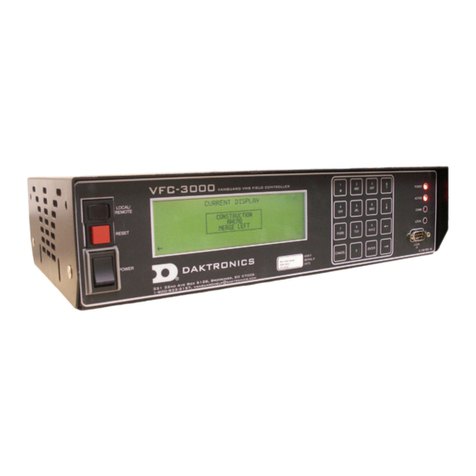
Daktronics VFC-3000 User manual

Daktronics

Daktronics VFC-3000 User manual

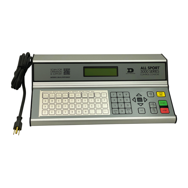
Daktronics ALL-SPORT 5000 Manual

Daktronics

Daktronics ALL-SPORT 5000 Manual

Daktronics SPORTSOUND SSR-200 GEN II User manual

Daktronics

Daktronics SPORTSOUND SSR-200 GEN II User manual

Daktronics OMNISPORT 2000 User manual

Daktronics

Daktronics OMNISPORT 2000 User manual

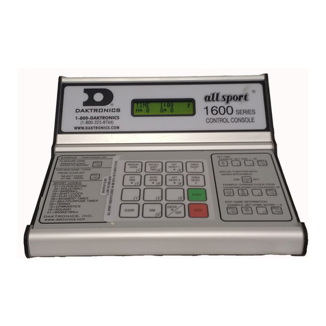
Daktronics All Sport 1600 Series User manual

Daktronics

Daktronics All Sport 1600 Series User manual

Daktronics ALL SPORT 100 User manual

Daktronics

Daktronics ALL SPORT 100 User manual

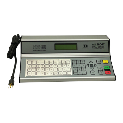
Daktronics All Sport 5000 User manual

Daktronics

Daktronics All Sport 5000 User manual

Daktronics VS-5000 Series User manual

Daktronics

Daktronics VS-5000 Series User manual

Daktronics FLR 1500 User manual

Daktronics

Daktronics FLR 1500 User manual

Daktronics VF-24 Series User manual

Daktronics

Daktronics VF-24 Series User manual

Daktronics 5000 Series User manual

Daktronics

Daktronics 5000 Series User manual

Popular Controllers manuals by other brands

ARIS Tensor Zone 2/22 manual

ARIS

ARIS Tensor Zone 2/22 manual

Emerson Fisher FIELDVUE DVC6200 HW2 Instruction manual supplement

Emerson

Emerson Fisher FIELDVUE DVC6200 HW2 Instruction manual supplement

Ventis Controller instruction manual

Ventis

Ventis Controller instruction manual

ABB ACS 6000 Service and maintenance manual

ABB

ABB ACS 6000 Service and maintenance manual

E-T-A E-1071-623 manual

E-T-A

E-T-A E-1071-623 manual

SGM Studio 12 user manual

SGM

SGM Studio 12 user manual

Homematic IP HmIP-DRDI3 Installation and operating manual

Homematic IP

Homematic IP HmIP-DRDI3 Installation and operating manual

Mitsubishi Electric FX2N-64DP-M Hardware manual

Mitsubishi Electric

Mitsubishi Electric FX2N-64DP-M Hardware manual

Hardi HC5500 quick guide

Hardi

Hardi HC5500 quick guide

LEGRAND Tynetec ZXT473 manual

LEGRAND

LEGRAND Tynetec ZXT473 manual

NEC N8803-034 user guide

NEC

NEC N8803-034 user guide

Projoy Electric PEFS-24V-CN Series user manual

Projoy Electric

Projoy Electric PEFS-24V-CN Series user manual

SOMFY animeo IB + 1822064 installation guide

SOMFY

SOMFY animeo IB + 1822064 installation guide

AirCom RGB4 operating manual

AirCom

AirCom RGB4 operating manual

Derale Perfomance 16797 Nstallation instructions

Derale Perfomance

Derale Perfomance 16797 Nstallation instructions

E-T-A EM12D-TMB Series instruction manual

E-T-A

E-T-A EM12D-TMB Series instruction manual

Panasonic FP7 Series user manual

Panasonic

Panasonic FP7 Series user manual

Mitsubishi Electric Q Series Programming manual

Mitsubishi Electric

Mitsubishi Electric Q Series Programming manual

manuals.online logo
manuals.online logoBrands
  • About & Mission
  • Contact us
  • Privacy Policy
  • Terms and Conditions

Copyright 2025 Manuals.Online. All Rights Reserved.