manuals.online logo
Brands
  1. Home
  2. •
  3. Brands
  4. •
  5. Daktronics
  6. •
  7. Media Player
  8. •
  9. Daktronics Big Stream 2 User manual

Daktronics Big Stream 2 User manual

Other Daktronics Media Player manuals

Daktronics DMP-8000 Series User manual

Daktronics

Daktronics DMP-8000 Series User manual

Daktronics Big Stream 1 User manual

Daktronics

Daktronics Big Stream 1 User manual

Daktronics DMP-5000 Series User manual

Daktronics

Daktronics DMP-5000 Series User manual

Popular Media Player manuals by other brands

VidaBox LUX installation guide

VidaBox

VidaBox LUX installation guide

CasaTunes CT-3S quick start guide

CasaTunes

CasaTunes CT-3S quick start guide

Yamaha TSX-112 owner's manual

Yamaha

Yamaha TSX-112 owner's manual

Fantec MM-FHDL user manual

Fantec

Fantec MM-FHDL user manual

Visual Land Impulse quick start guide

Visual Land

Visual Land Impulse quick start guide

Philips GoGear Muse SA2MUS08 quick start guide

Philips

Philips GoGear Muse SA2MUS08 quick start guide

Fantec MM-HDRL user manual

Fantec

Fantec MM-HDRL user manual

Kvarta DVB Streamer quick start

Kvarta

Kvarta DVB Streamer quick start

Dune HD Duo 4K user manual

Dune HD

Dune HD Duo 4K user manual

Camos MMS-1000 manual

Camos

Camos MMS-1000 manual

Energy 75 Series user manual

Energy

Energy 75 Series user manual

Z3 Technology DME-03 user guide

Z3 Technology

Z3 Technology DME-03 user guide

Sony SVR-2000 Dimensions

Sony

Sony SVR-2000 Dimensions

Meicheng HD-1080K12 user manual

Meicheng

Meicheng HD-1080K12 user manual

DENAFRIPS ARCE owner's manual

DENAFRIPS

DENAFRIPS ARCE owner's manual

Topaz CMS Media Player Hardware user manual

Topaz

Topaz CMS Media Player Hardware user manual

InFocus LightCast user guide

InFocus

InFocus LightCast user guide

Samsung MP-80S Owner's instructions

Samsung

Samsung MP-80S Owner's instructions

manuals.online logo
manuals.online logoBrands
  • About & Mission
  • Contact us
  • Privacy Policy
  • Terms and Conditions

Copyright 2025 Manuals.Online. All Rights Reserved.

Big Stream 2 Quick Guide
DD4734683
Rev 01
08 December 2020
201 Daktronics Drive
Brookings, SD 57006-5128
www.daktronics.com/support
800.325.8766
Page 1 of 12
This guide explains the setup of a Daktronics “Big Stream 2” system.
This portable system includes a Digital Media Player (DMP) that
provides an NDI (Network Device Interface) video output to a
compatible customer-provided streaming device. Content is created
and played using the Daktronics Show Control System. For more
information about Show Control System installation, registration, or
operation, refer to the documentation provided with the software.
Refer also to the following YouTube playlist:
https://www.youtube.com/watch?v=vbXFr2aSrnM&list=PL2dNnauPij
WWHWyn9LKphHE0SjkkkwJP3
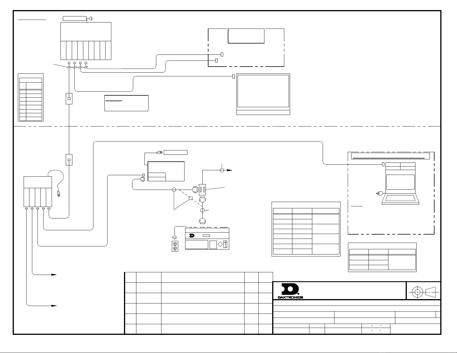
Refer to DWG-4694089 for rack schematics and DWG-4694090 for
rack specications. Site-specic diagrams may also be available;
these will take precedence over any general instructions found in
this guide. Contact the Daktronics Standard Order Project Manager
(SOPM) or Standard Order Project Coordinator (SOPC) to ask if any
site-specic drawings exist for the project.
Equipment Setup
1. Unpack all items and verify everything from the Bill of Materials
(BOM) is included.
2. Place the portable control rack at the desired operator location,
and remove the cover
panels to access the internal
components and connections.
3. Place the Show Control laptop
on the top shelf of the rack
case, and use the plastic
clamps to hold it in place.
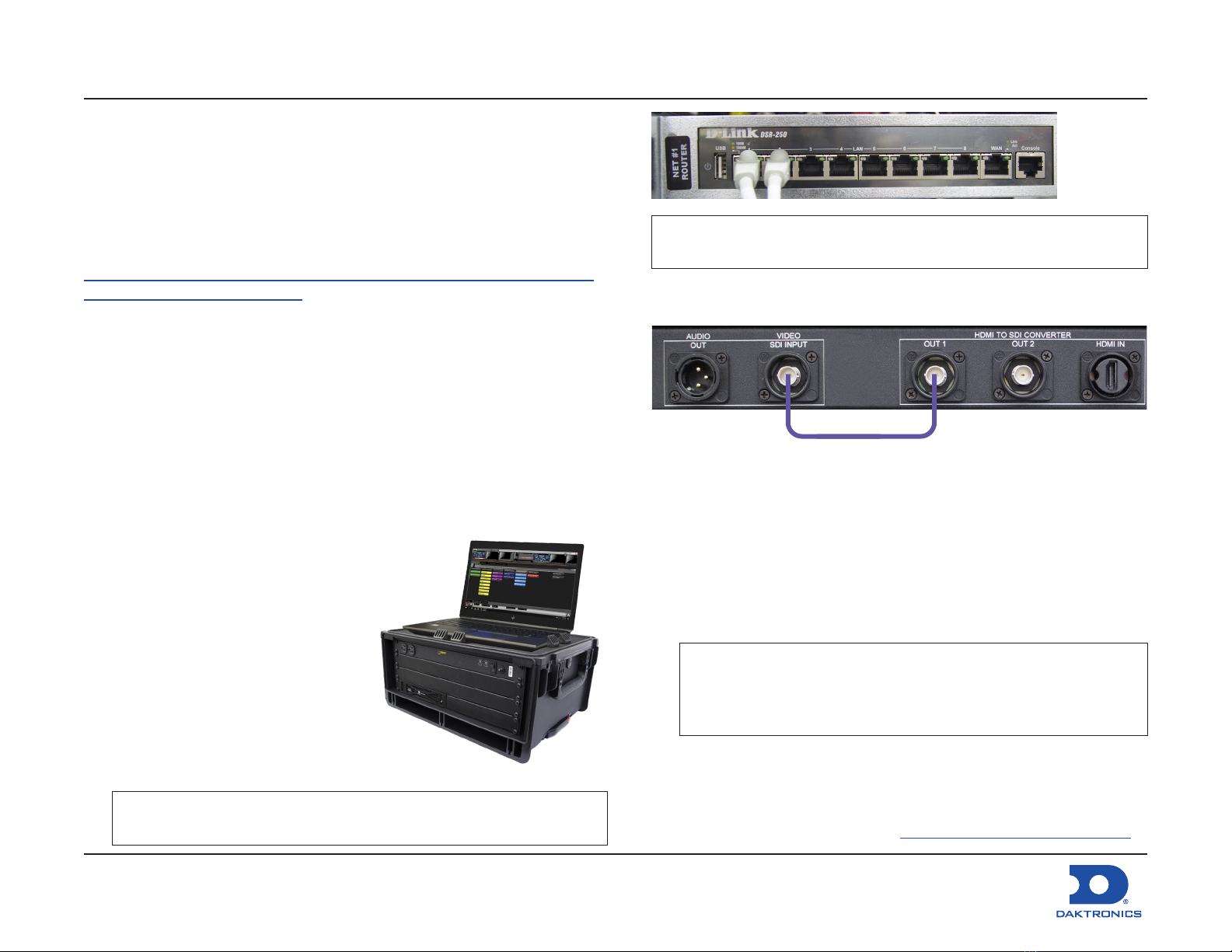
4. Route the supplied Cat5
network cable through the hole
in the top of the rack case and
connect it to the Show Control
laptop's network jack.
Note: If the Show Control laptop will be located elsewhere, a
100' Cat5 network cable is supplied for this purpose.
Note: An Internet (WAN) connection into the network router in
the rack is required to output the streaming video online.
5. Bring a video source into the appropriate input jack on the rear of
the rack.
• SDI: Connect to the SDI INPUT jack on VPP #1.
• HDMI: Connect to the HDMI IN jack on VPP #1, then connect
the 15" violet coaxial cable (part # W-3896406) between the
OUT 1 jack and the SDI INPUT jack.
• Analog (Not Provided by Daktronics): If using an analog video
signal, an analog-to-SDI converter will need to be sourced by
the customer. Connect coaxial cable with BNC connectors
between the SDI output jack on the converter and the SDI IN
jack on VPP #1.
Note: The converter may have settings to adjust depending
on the type of analog signal (component, composite,
etc.) coming in. Refer to the documentation provided
with the converter for proper input settings.
6. Plug power cords for all devices (portable control rack, Show
Control laptop, monitors, etc.) into standard wall outlets.
7. After turning on the Show Control computer, ensure it is licensed.
Refer to the Show Control Software Licensing Quick Guide
(DD1785842), available online at www.daktronics.com/manuals.
W-3896406
Big Stream 2 Quick Guide
DD4734683
Rev 01
08 December 2020
201 Daktronics Drive
Brookings, SD 57006-5128
www.daktronics.com/support
800.325.8766
Page 2 of 12
Cong Proles
The system ships congured with a 720p output by default.
To change the output resolution to 1080p:
1. Open a web browser and go to http://192.168.0.237/#proles to
access the DMP-8000 Cong Proles window.
Note: If asked to enter login credentials, the defaults are
Username: vnet and Password: dakpassv.
2. Select 1080p NDI Ouput.
3. Click Continue when the conrmation message opens.
4. Wait for the player to restart. A green check mark indicates when
the process is completed.
Reusing Existing Content
In general, Daktronics recommends creating new content specically
for streaming using the correct output resolutions (720p = 720 x 1280
or 1080p = 1080 x 1920).
Depending on the size and aspect ratio of existing display content,
it may be possible to reuse the les for streaming. Otherwise, the
content may still need to be recreated. For example, if you have
a small 132 x 176 display with a 4:3 aspect ratio, streaming its
content will not only cause pixelation due to upscaling, it will also be
stretched to t the width, giving it more of a squished appearance:
Before
132 x 176 (4:3)
After
720 x 1280 (16:9)
#8#8
JACOBSJACOBS
MICHELLEMICHELLE
However, if you already have a display with a 16:9 aspect ratio, the
content will better t the aspect ratio of the streaming output. The
content can still become pixelated, depending on how much it
needs to upscale, but this can work if time or resources are limited
before a scheduled event.
Big Stream 2 Quick Guide
DD4734683
Rev 01
08 December 2020
201 Daktronics Drive
Brookings, SD 57006-5128
www.daktronics.com/support
800.325.8766
Page 3 of 12
Optional TriCaster Mini Setup
Refer to the instructions below and DWG-4715862 to set up the
optional TriCaster Mini switcher and replay system. For more
information, also refer to the TriCaster User Guide
(http://new.tk/Manual-TC1-V2).
1. Remove the TriCaster Mini, Launchpad Mini, mouse, keyboard,
and power adapters from the travel case. Set up this equipment
– and the TimeWarp device – within 25' of the control rack.
2. Place one 22" ViewSonic monitor at the Replay operator location
and the other 22" ViewSonic monitor at the TriCaster switcher
operator location. Both monitors should be within 6' of the
TriCaster Mini.
3. Make the following connections to the TriCaster Mini:
3a
3g
3c 3e
3f
3b
3d
3h
a. Connect BNC cables from up to four cameras to
VIDEO IN 1-4
.
b. Connect the 25' BNC cable (part # W-1971) between a VIDEO
OUT jack and the SDI INPUT jack on the rear of the rack.
c. Connect the 1/8"-to-1/4" adapter into the 1/8" TriCaster
operator monitor audio cable, and then plug the adapter
into the PHONES jack. The other end of the audio cable
connects to the monitor’s AUDIO IN jack.
d. If there is an audio system, connect the 25' 1/4"-to-XLR cable
(part # W-4717001) between the AUDIO OUT L jack and an
available input on the audio mixer.
e. Plug the supplied mouse, keyboard, TimeWarp, and
Launchpad Mini devices into available USB ports.
f. Connect the 25' network cable (part # W-4638308) between
a NETWORK jack and an open jack on the network router in
the control rack.
g. Connect one Mini-DisplayPort-to-DisplayPort adapter into
one 6' DisplayPort cable, and then plug the adapter into
one of the Mini DisplayPort jacks. The other end of the cable
connects to the 22" Replay operator monitor. Repeat this to
also connect the 22" TriCaster operator monitor.
h. Connect the power adapter into the DC IN jack.
4. Plug power cords for all devices (TriCaster Mini, monitors, etc.)
into standard wall outlets.
Big Stream 2 Quick Guide
DD4734683
Rev 01
08 December 2020
201 Daktronics Drive
Brookings, SD 57006-5128
www.daktronics.com/support
800.325.8766
Page 4 of 12
NDI Output to Streaming Device
This section describes an optional method of streaming the NDI
output from the Big Stream DMP via a TriCaster. Other devices/
software may be used instead as long as they accept the NDI video
source. If the streaming device does not accept NDI, the NDI output
must be converted to a video input that the streaming device can
accept using a converter such as the BirdDog NDI Encoder/Decoder.
Note: The streaming device must be connected into an open jack
on the network router in the control rack.
In typical Daktronics video control systems, the TriCaster acts as
a switcher for up to 4 video inputs. For the Big Stream system, the
TriCaster Mini may also function as the streaming device. For more
information about connections to the TriCaster, refer to Page 2.
Capturing the NDI Output
Each monitor on the TriCaster workspace can be congured to show
any input or output. There are multiple virtual inputs that can be set
to the NDI feed from the DMP.
1. Open the TriCaster program and start the desired session.
2. Right click an unused monitor, such as GFX1, and go to Inputs >
INPUT 5.
3. Click the gear icon in the lower-right of the Input 5 monitor to
open the input settings.
a. In the Source drop-down list, select D8STREAM-P and then
NDI-0.
b. Expand the Name/Comment section. Rename Video
to D8STREAM and Button to DMP, and add a descriptive
Comment as desired.
c. Click Close when nished.
Note: If content is playing out of the DMP, it will appear in the
D8STREAM monitor.
Big Stream 2 Quick Guide
DD4734683
Rev 01
08 December 2020
201 Daktronics Drive
Brookings, SD 57006-5128
www.daktronics.com/support
800.325.8766
Page 5 of 12
Streaming the NDI Output
1. Click the STREAM/ENCODE button at the top of the screen.
2. Click Source Setup.
MIX 1 is the primary output to the display*. Mix 4 is the replay mix.
MIX 2 will be used for the separate streaming mix.
a. Change MIX 2 Video to M/E 2.
b. Change STREAM 1 Video to MIX 2.
c. Adjust the Audio output source if desired.
3. Click the STREAM 1 gear icon and adjust the encoder settings as
desired. The default settings should work for most applications.
Click OK when nished.
4. Check the streaming platform(s). Hover over and select the
settings gear icon to log in to an account or adjust as needed.
5. Close out of all settings windows when nished.
Big Stream 2 Quick Guide
DD4734683
Rev 01
08 December 2020
201 Daktronics Drive
Brookings, SD 57006-5128
www.daktronics.com/support
800.325.8766
Page 6 of 12
6. Back on the main interface, select DMP on the M/E 2 bar.
Selecting DMP on the M/E 2 bar will make it the active M/E 2
source. The active M/E 2 source is MIX 2, which is the congured
streaming source.
TriCaster Registration
On rst time start-up, the installer may assist in registering the
TriCaster for the end user. This can be done very easily if an internet
connection is available. If not, call NewTek Customer Service:
• (US) 1-800-862-7837
• (Outside US) +1-210-370-8452
Both the Serial Number (located on the TriCaster unit) and Product ID
(presented during registration) are required to obtain the necessary
Registration Code.
For more information about registration, operation, or troubleshooting
of the TriCaster system, visit www.newtek.com/support/get-support.
For More Information
To learn more about the Daktronics Show Control System software,
consult the Show Control System User Handbook:
• Press the Windows key [ ] and go to All Programs > Daktronics >
Display Studio > Show Control System User Handbook.
• From within Display Studio, press the Display Studio Hub button
and select Help.
Watch the following YouTube video for an introduction to Show
Control: www.youtube.com/watch?v=3Q28olggTGo
For any other questions, comments, or concerns, please contact
Daktronics Support Services:
United States & Canada
Toll Free: 1-800-DAKTRONICS (1-800-325-8766)
Outside the U.S. & Canada
+1-605-697-4000
Real-Time Data (Scoring & Timing)
This type of installation will often include an All Sport®5000 series
scoreboard control console, the All Sport Pro scoring system, and/or
a statistics computer for displaying Real-Time Data (RTD).
• If the All Sport is located in the same room, it may be possible to
run the cables directly to the network router without J-boxes.
• If the All Sport is in a separate location, install network J-boxes
and run Cat5 cable.
Refer to DWG-1053539 or DWG-4768575 for more information about
connecting RTD sources into the display control network.
Note: For information on setting up real-time data for track timing,
refer to the Track & Field Interfaces for Scoreboards &
Displays Setup Guide (DD3059635), available online at
www.daktronics.com/manuals.
TYPE
SCALE:
PROJ:
TITLE:
DESIGN:
DRAWN: DATE:
FUNC
SHEET
SIZE
JOB NO:REV
STANDARD VIDEO
RISER; STANDARD VIDEO, RTD, BASIC & EXTENDED STATS
SBRINK 16 MAY 11
P1453 F 03 A
NONE
SBRINK
1053539
06
THE CONCEPTS EXPRESSED AND DETAILS SHOWN ON THIS DRAWING
ARE CONFIDENTIAL AND PROPRIETARY. DO NOT REPRODUCE BY
ANY MEANS WITHOUT THE EXPRESS WRITTEN CONSENT OF
DAKTRONICS, INC. OR ITS WHOLLY OWNED SUBSIDIARIES.
COPYRIGHT 2019 DAKTRONICS, INC. (USA)
THIRD ANGLE PROJECTION
AH
STANDARD VIDEO
CONTROL OPTION
W-1343 (14')
120V ONLY
NET 4
NET 3
NET 1
NET 2
ROUTER
(PART# MAY VARY)
INTERNET
NET 5
NET 6
NET 7
NET 8
TO DMP
TO VIP / DI
*NOTE: SITE SPECIFIC RISER DIAGRAM(S)
TAKE PRECEDENCE OVER THIS OR ANY
OTHER STANDARD DRAWING.
SHOW CONTROL
COMPUTER
RACK ROOM
CONTROL ROOM
EQUIPMENT
PROJECT SPECIFIC
RJ45 J-BOX
0A-1177-1028
2"X4"
BRN
WHT/BRN
8-PIN RJ45
BLU
ORG
WHT/GRN
WHT/BLU
8
7
5
6
4
2
3
1
GRN
WHT/ORG
PIN# COLOR
WIRE
0A-1177-1028
W-1384
CAT5E
**NOTE**
CAT5E RUNS MUST BE
LESS THAN 250'
DATE:REV BY:
01 15 MAR 12 JJL
UPDATED TITLE
DATE:
REV BY:
02 21 FEB 19 MTR
UPDATED LANTRONICS VIEW
ADDED A-2907 DETAIL
DATE:
REV BY:
03 22 JUNE 20 RMG
CORRECTED SPELLING ERRORS
UPDATED DMP AND VIP LABELS
DATE:
REV BY:
04 30 OCT 20 IFB
ADDED DESCRIPTION BOX FOR ALL SPORT INTERFACE
UPDATED DMP AND VIP LABELS
RJ45 J-BOX
0A-1177-1028
2"X4"
NET 5
NET 4
NET 3
NET 1
NET 2
NET#2
A-2907
LAPTOP COMPUTER
STATS & DSTI
PRINTER
USB COM1
NETWORK
COMPUTER
BY CUSTOMER
NOTE:
DAKSTATS STATISTICS PROGRAM AND THE
DSTI INTERFACE PROGRAMS MAY BE
PURCHASED FROM DAKTRONICS.
STAT CREW STATISTICS PROGRAM IS
PROVIDED BY OTHERS.
EXPANDED STATS INTERFACE DETAIL:
ASSEMBLIES:
0A-1453-0115: KIT; STD VIDEO, A/S, RTD INPUT
0A-1453-0116: KIT; STD VIDEO, A/S, DAKSTATS RTD INPUT
0A-1453-0117: KIT; STD VIDEO, A/S, STATCREW RTD INPUT
CLOCK
GAME/SHOT
RTD
CL +
GND
VENUS
3
7
14
19
18
17
16
15
PIN#
1+ SCBD
LOCKER ROOM
3-
3+
2-
2+
1-
CLOCKS
OUTPUT
OUTPUT # SIGNAL
JB1:J1 ALLSPORT J1 OUTPUT TABLE
2
3
PIN#
RX RS-232
TX RTD
OUTPUT # SIGNAL
JB1:J2 ALLSPORT J2 OUTPUT TABLE
7 GND
ALLSPORT
J7 J6 J4 J3 J1
5XXX
JB1
0A-1166-0027
DUAL 25-P J-BOX, 2"X4"
W-1247, 25'
J5
0A-1453-0033, 10'
TO FIBER CONVERTER CARD OR
DIRECTLY TO SCOREBOARD
22AWG SHIELDED PAIR
COPPER CABLE
(2) 15AMP
DUPLEX RECEPTACLE
BY CUSTOMER
W-1343 (14')
120V ONLY
10/100
SERIAL
LANTRONIX
SCV #1
-DHCP
-19200
TO CUSTOMER
STATCREW COMPUTER
(IF APPLICABLE)
ALTERNATE SHOW
CONTROL CONNECTION
LOCATION
DATE:REV BY:
05 10 NOV 20 IFB
CHANGED VERTICAL A BORDER TO HORIZONTAL
DATE:
REV BY:
06 16 NOV 20 IFB
UPDATED DVXMC TO STANDARD VIDEO CONTROL
P
P
a
a
r
r
t
t
#
#
-
-
D
D
W
W
G
G
-
-
0
0
1
1
0
0
5
5
3
3
5
5
3
3
9
9
V
V
e
e
r
r
s
s
i
i
o
o
n
n
-
-
0
0
6
6
.
.
2
2
D
D
e
e
s
s
c
c
r
r
i
i
p
p
t
t
i
i
o
o
n
n
-
-
N
N
A
A
R
R
I
I
S
S
E
E
R
R
;
;
S
S
T
T
D
D
V
V
I
I
D
D
,
,
R
R
T
T
D
D
,
,
B
B
A
A
S
S
I
I
C
C
&
&
E
E
X
X
T
T
E
E
N
N
D
D
E
E
D
D
S
S
T
T
A
A
T
T
S
S
L
L
i
i
f
f
e
e
c
c
y
y
c
c
l
l
e
e
S
S
t
t
a
a
t
t
e
e
-
-
F
F
u
u
l
l
l
l
P
P
r
r
o
o
d
d
u
u
c
c
t
t
i
i
o
o
n
n
L
L
a
a
s
s
t
t
M
M
o
o
d
d
i
i
f
f
i
i
e
e
d
d
B
B
y
y
-
-
i
i
b
b
r
r
a
a
n
n
d
d
t
t
L
L
a
a
s
s
t
t
M
M
o
o
d
d
i
i
f
f
i
i
e
e
d
d
-
-
2
2
0
0
2
2
0
0
-
-
1
1
1
1
-
-
1
1
6
6
STANDARD VIDEO
CONTROL OPTION
W-1343 (14')
120V ONLY
NET 4
NET 3
NET 1
NET 2
ROUTER
(PART# MAY VARY)
INTERNET
NET 5
NET 6
NET 7
NET 8
TO DMP
TO VIP / DI
*NOTE: SITE SPECIFIC RISER DIAGRAM(S)
TAKE PRECEDENCE OVER THIS OR ANY
OTHER STANDARD DRAWING.
RACK ROOM
CONTROL ROOM
EQUIPMENT
PROJECT SPECIFIC
0A-2125-7000
WIRELESS AP KIT
REQUIRED WHEN
USING THE ALL
SPORT PRO IPAD
RJ45 J-BOX
0A-1177-1028
2"X4"
W-1384
CAT5E
**NOTE**
CAT5E RUNS MUST BE
LESS THAN 250'
BRN
WHT/BRN
8-PIN RJ45
BLU
ORG
WHT/GRN
WHT/BLU
8
7
5
6
4
2
3
1
GRN
WHT/ORG
PIN# COLOR
WIRE
0A-1177-1028
SHOW CONTROL
COMPUTER
ALL SPORT PRO
SOFTWARE INSTALLED
ON SCS COMPUTER
LAPTOP COMPUTER
STATS & DSTI
PRINTER
USB COM1
NETWORK
COMPUTER
BY CUSTOMER
NOTE:
DAKSTATS STATISTICS PROGRAM AND THE
DSTI INTERFACE PROGRAMS MAY BE
PURCHASED FROM DAKTRONICS.
STAT CREW STATISTICS PROGRAM IS
PROVIDED BY OTHERS.
EXPANDED STATS INTERFACE DETAIL:
ALL SPORT PRO
TABLET
A-4298304
FRONT VIEW
ALL SPORT PRO
INTERFACE
0A-1196-0501
LINE OF SIGHT RADIO
COMMUNICATIONS TO LOCAL WIRELESS
SCORING SYSTEM, IF EQUIPPED
INSTALLER NOTE:
CLEAR LINE OF SIGHT
RECOMMENDED BETWEEN
ACCESS POINT AND TABLET
RJ45 J-BOX
0A-1177-1028
2"X4"
JB1
0A-1065-0056
25-P J-BOX, 2"X4"
W-1247, 25'
TO FIBER CONVERTER CARD OR
DIRECTLY TO SCOREBOARD
22AWG SHIELDED PAIR
COPPER CABLE
(2) 15AMP
DUPLEX RECEPTACLE
BY CUSTOMER
TO CUSTOMER
STATCREW COMPUTER
(IF APPLICABLE)
ALTERNATE SHOW
CONTROL CONNECTION
LOCATION
CONFIGURATION #
117800
201DAKTRONICS DR. BROOKINGS SD
1-800-DAKTRONICS(1-800-325-8766)
+1-605-697-4000
WWW.DAKTRONICS.COM
MADEIN THE U.S.A.
DAKTRONICS
IF APPLICABLE
0A-1196-0511: ALL SPORT PRO
INTERFACE KIT
CLOCK
GAME/SHOT
RTD
CL +
GND
VENUS
3
7
14
19
18
17
16
15
PIN#
1+ SCBD
LOCKER ROOM
3-
3+
2-
2+
1-
CLOCKS
OUTPUT
OUTPUT # SIGNAL
JB1:J1 ALLSPORT J1 OUTPUT TABLE
THE CONCEPTS EXPRESSED AND DETAILS SHOWN ON THIS DRAWING
ARE CONFIDENTIAL AND PROPRIETARY. DO NOT REPRODUCE BY
ANY MEANS WITHOUT THE EXPRESS WRITTEN CONSENT OF
DAKTRONICS, INC. OR ITS WHOLLY OWNED SUBSIDIARIES.
COPYRIGHT 2019 DAKTRONICS, INC. (USA)
THIRD ANGLE PROJECTION
REV
TITLE:
PROJECT:
INCHES [MILLIMETERS]
DESIGN:
SCALE:
DIM UNITS:DATE: SHEET
DO NOT SCALE DRAWING
FUNC - TYPE - SIZE
DRAWN: -
JOB NO.
-
STANDARD VIDEO
RISER; STANDARD VIDEO, ALL SPORT PRO, STATS
IBRANDT
06 NOV 20
P1920 F 03 A
NONE
HBONER 4768575
01
POE
(1) 15AMP
DUPLEX
RECEPTACLE
BY CUSTOMER
RJ45
W-2227
(100FT)
RACK
ROOM
WALL
0A-2125-7300: WIRELESS CLIENT
TO ALL SPORT PRO TABLET
MOUNTING
PLATE, WALL
OR POLE
MOUNT
SUPPLIED WITH POE
W-1542
IN LINE OF SIGHT WITH COURT SIDE TABLE
AH
REV DATE: BY:
01 16 NOV 20 IFB
UPDATED SIZE OF DWG
THE CONCEPTS EXPRESSED AND DETAILS SHOWN ON THIS DRAWING
ARE CONFIDENTIAL AND PROPRIETARY. DO NOT REPRODUCE BY
ANY MEANS WITHOUT THE EXPRESS WRITTEN CONSENT OF
DAKTRONICS, INC. OR ITS WHOLLY OWNED SUBSIDIARIES.
COPYRIGHT 2019 DAKTRONICS, INC. (USA)
THIRD ANGLE PROJECTION
BH
REV
TITLE:
PROJECT:
INCHES [MILLIMETERS]
DESIGN:
SCALE:
DIM UNITS:DATE: SHEET
DO NOT SCALE DRAWING
FUNC - TYPE - SIZE
DRAWN: -
JOB NO.
-
SPORTS VIDEO SYSTEMS
KIT; TRICASTER MINI ADVANCED SDI W/ TRAVEL CASE
TKELLEY
28 JULY 20
P1453 F 01 B
NONE
TKELLEY 4715862
00
A-3343
TRICASTER 850 TW
USB
RMT #1
SUPPLIED W/ A-3443
W-4638308
USB
LAUNCHPAD MINI MK3
A-3450
RMT #2
DVI IN
VGA IN VIEWSONIC
22"
VA2251M-LED
A-2430
AUDIO IN
DP IN
GPM #1
DVI IN
VGA IN VIEWSONIC
22"
VA2251M-LED
A-2430
AUDIO IN
DP IN
GPM #2
SDI OUT 1
SDI OUT 2
USB 3.0 1
USB 3.0 2
TRICASTER
MINI
ADVANCED
HD-4 SDI
A-4715564
SDI IN 2
SDI IN 3
SDI IN 4
AUDIO IN L
AUDIO IN R
USB 3.1
NETWORK 1
USB 2.0 1
USB 2.0 2 USB 3.0 4
USB 3.0 3
MINI DP 1
MINI DP 2
MINI DP 3
SDI IN 1
USB-C
MINI DP 4
NETWORK 2
MIC IN
AUD OUT L
AUD OUT R
AUD PHONE
* MINI DP
ADAPTERS
INCLUDED W/
TRICASTER
W-2494
MDP TO DP*
MDP TO DP*
SWT #1
MOUSE
KEYBOARD
TO CONSUMER
AUDIO SYSTEM
SUPPLIED W/ A-3450
***NOTE: THE TRICASTER MINI AND ITS
ACCESSORIES ARE STORED IN A TRAVEL CASE
TO NETWORK
ROUTER
TO DMP-8221
SDI INPUT
TRICASTER EXTENSION KIT EQUIPMENT LIST
PART DESCRIPTION PART NUMBER QUANTITY
22" MONITORS A-2430 2
TIME WARP 850TW REPLAY CONTROLLER A-3343 1
LAUNCHPAD MINI MK3 A-3450 1
TRICASTER MINI ADVANCED SDI A-4715564 1
TRICASTER MINI TRAVEL CASE EN-4715565 1
25' BNC VIDEO CABLE W-1971 1
ADAPTER; 1/4" PLUG TO 1/8" JACK W-2494 1
6' DISPLAYPORT CABLE W-3271379 2
6FT 1/8" TO 1/8" STEREO CABLE W-3511512 1
25FT CAT5E NETWORK CABLE W-4638308 1
25FT 1/4" TRS PLUG TO XLR M CABLE W-4717001 2
INSTALLATION NOTES:
1. REMOVE TRICASTER, MOUSE, KEYBOARD, AND POWER ADAPTER FROM THE TRAVEL CASE.
2. SET UP EQUIPMENT ON COUNTER WITHIN 25' OF VIDEO RACK.
3. CONNECT (2) MINI DISPLAYPORT TO DISPLAYPORT VIDEO ADAPTERS TO THE TRICASTER.
4. CONNECT THE TWO MONITORS WITH THE INCLUDED DISPLAYPORT CABLES.
5. SET THE CONTROLLERS NEAR ONE OF THE MONITORS AND CONNECT THE USB TO THE TRICASTER.
6. CONNECT THE INCLUDED NETWORK CABLE BETWEEN THE TRICASTER AND SITE NETWORK ROUTER.
7. CONNECT THE INCLUDED BNC VIDEO CABLE BETWEEN THE TRICASTER AND THE DMP IN THE VIDEO RACK.
8. REFER TO BIG STREAM QUICK GUIDE FOR SETUP AND OPERATION.
***NOTE: SITE SPECIFIC RISER DIAGRAM(S) TAKE PRECEDENCE
OVER THIS OR ANY OTHER STANDARD DRAWING.
W-3271379
W-3271379
W-3511512
W-4717001
W-1971
P
P
a
a
r
r
t
t
#
#
-
-
D
D
W
W
G
G
-
-
0
0
4
4
7
7
1
1
5
5
8
8
6
6
2
2
V
V
e
e
r
r
s
s
i
i
o
o
n
n
-
-
0
0
0
0
.
.
1
1
D
D
e
e
s
s
c
c
r
r
i
i
p
p
t
t
i
i
o
o
n
n
-
-
N
N
B
B
K
K
I
I
T
T
;
;
T
T
R
R
I
I
C
C
A
A
S
S
T
T
E
E
R
R
M
M
I
I
N
N
I
I
A
A
D
D
V
V
S
S
D
D
I
I
W
W
/
/
T
T
R
R
A
A
V
V
E
E
L
L
C
C
A
A
S
S
E
E
L
L
i
i
f
f
e
e
c
c
y
y
c
c
l
l
e
e
S
S
t
t
a
a
t
t
e
e
-
-
F
F
u
u
l
l
l
l
P
P
r
r
o
o
d
d
u
u
c
c
t
t
i
i
o
o
n
n
L
L
a
a
s
s
t
t
M
M
o
o
d
d
i
i
f
f
i
i
e
e
d
d
B
B
y
y
-
-
t
t
k
k
e
e
l
l
l
l
e
e
y
y
L
L
a
a
s
s
t
t
M
M
o
o
d
d
i
i
f
f
i
i
e
e
d
d
-
-
2
2
0
0
2
2
0
0
-
-
0
0
8
8
-
-
2
2
1
1
This page intentionally left blank.