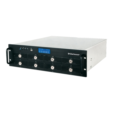
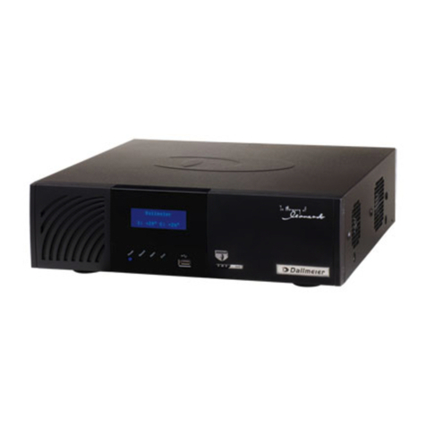
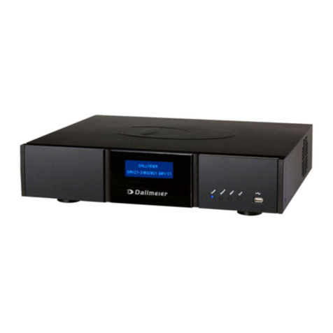
dallmeier DIS-1/S User manual

Installation and Configuration
Rev. 1.0.0 / 071106
Englisch
DIS-1/S
Recorder and Streamer

DIS-1/S
2Dallmeier electronic
Copyright © Dallmeier electronic GmbH & Co.KG
All rights reserved. This document may not be copied, photocopied, reproduced, translated, transferred to
an electronic medium or converted to a machine-readable form either whole or in part without first receiving
written permission from Dallmeier electronic GmbH & Co.KG.
We reserve the right to make technical modifications.
The manufacturer accepts no liability for damage to property or pecuniary damages arising due to minor
defects of the product or documentation, e.g. print or spelling errors, and for those not caused by intention
or gross neglegence of the manufacturer.
Dallmeier electronic GmbH & Co.KG
Cranachweg 1
D 93051 Regensburg, Germany
www.dallmeier-electronic.com

DIS-1/S
3Dallmeier electronic
Table of contents
1 About this document.................................................................................. 5
1.1 Validity .......................................................................................................... 5
1.2 Documents on the unit .................................................................................. 5
1.3 Convention ................................................................................................... 5
2 Safety instructions ..................................................................................... 7
3 General notes.............................................................................................. 9
3.1 Scope of delivery.......................................................................................... 9
3.2 Transportation and packaging....................................................................... 9
3.3 Warranty ....................................................................................................... 9
4 Installation and mounting........................................................................ 10
4.1 Requirements at the installation site........................................................... 10
4.2 Stand-alone installation............................................................................... 10
4.3 Installation in a 19" equipment cabinet ....................................................... 10
4.4 Removal ..................................................................................................... 11
5 Views and connection assignment......................................................... 12
5.1 Front view / status LEDs............................................................................ 12
5.2 Back view / connection assignment.......................................................... 12
5.3 Contact IN................................................................................................... 13
6 Start up and login ..................................................................................... 14
6.1 Start up ....................................................................................................... 14
6.2 Login ........................................................................................................... 14
6.3 Operating interface ..................................................................................... 15
7 Basic settings ........................................................................................... 16
7.1 Language .................................................................................................... 16
7.2 User interface - Player ............................................................................... 16
7.3 Setting date and time.................................................................................. 18
7.3.1 Date/Time ................................................................................................... 18
7.3.2 Timezone .................................................................................................... 19
7.3.3 Timerserver ................................................................................................ 19
7.4 Setting the video standard .......................................................................... 19
7.5 Setting camera name ................................................................................. 20
7.6 Changingpassword..................................................................................... 20
7.7 Event log..................................................................................................... 21
8 Interfaces ................................................................................................... 22
8.1 COM interface ............................................................................................ 22
8.2 IR interface ................................................................................................. 23
9 Network settings....................................................................................... 24
9.1 General settings.......................................................................................... 24

DIS-1/S
4Dallmeier electronic
9.2 Alarm host .................................................................................................. 24
9.2.1 Setting up an Alarm host............................................................................. 25
9.2.2 Time control................................................................................................ 26
9.2.2.1 Set week schedule...................................................................................... 26
9.2.2.2 Exceptions to the weekly plan .................................................................... 27
9.2.3 Editing and copying .................................................................................... 29
9.3 Video streaming.......................................................................................... 29
9.3.1 Configuring the DIS as a server.................................................................. 30
9.3.2 Protocol and encryption .............................................................................. 30
9.3.3 Multicast / unicast ....................................................................................... 30
9.3.4 Range restricition........................................................................................ 31
9.3.5 Packet size ................................................................................................. 31
9.3.6 Configuring a server using the DaVid-Protocol........................................... 31
9.3.7 Configuring the DIS as a client ................................................................... 32
10 Recording settings ................................................................................... 33
10.1 Track configuration ..................................................................................... 33
10.1.1 Creating tracks............................................................................................ 33
10.1.2 Delete recordings on a track ....................................................................... 34
10.1.3 Encoder settings ......................................................................................... 34
10.2 Selecting record mode................................................................................ 36
10.2.1 Permanent .................................................................................................. 37
10.2.2 Contact ....................................................................................................... 37
10.2.3 Contact with timer ....................................................................................... 37
10.2.4 Contact start / stop...................................................................................... 38
10.2.5 IR start / stopp ............................................................................................ 38
10.2.6 Motion detection ......................................................................................... 38
10.2.7 DaVid start/stop .......................................................................................... 40
10.2.8 Use scheduler ............................................................................................. 40
10.2.9 Event recording .......................................................................................... 40
10.2.10 Recording „Off“ ........................................................................................... 41
10.3 Scheduler.................................................................................................... 42
10.3.1 Setting time limits for recording modes ...................................................... 42
10.3.2 Exceptions in the week timer...................................................................... 44
10.4 Video settings ............................................................................................. 45
10.4.1 Image adjustment ....................................................................................... 46
10.4.2 Noise filters................................................................................................. 46
10.5 Fieldcontact display .................................................................................... 47
10.5.1 Fieldcontact display filters .......................................................................... 48
10.5.2 Fieldcontact display position....................................................................... 48
11 Service ....................................................................................................... 50
12 Appendix ................................................................................................... 51
13 Technical data ........................................................................................... 52

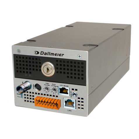
DIS-1/S
5Dallmeier electronic
1 About this document
1.1 Validity
This document applies to the recorder and streamer DIS-1/S (DIS). It has been produced
on the basis of version 2.0.11 (software).
1.2 Documents on the unit
Operating instructions
The document entitled "Operating Instructions" contains detailed descriptions on how to
operate the unit. General information on the appropriate use and maintenance is also
provided.
Thetargetaudienceofthis document is theoperatorofthe unit ("user"). Nospecialtechnical
knowledge is required.
Store this document in an accessible location near the product and keep it in readable
condition. Pass on this document to each successive owner or user of the product.
Installation and Configuration (this document)
The document entitled "Installation and Commissioning" contains detailed descriptions of
the installation, connection, commissioning and configuration of the unit. Safety notes,
general information and technical data are additionally provided.
The target audience of this document is exclusively specially trained and authorized
professionals ("installers").
1.3 Convention
This document contains various warning words and symbols that indicate potential sources
of danger. Various symbols and formats are used to maintain the clarity of the document.
DANGER
The warning word DANGER denotes an immediate danger
that may cause death or serious injury if it is not averted.
WARNING
The warning word WARNING denotes a possible danger that
may cause death or serious injury if it is not averted.
CAUTION
The warning word CAUTION denotes a possible danger that
may cause minor injury if it is not averted.
IMPORTANT
The word IMPORTANT denotes information for preventing
damage, incorrect configurations or incorrect actions.

DIS-1/S
6Dallmeier electronic
NOTE
A NOTE offers information on principles, special features and
efficient procedure as well as general recommendations.
Expression Expressions in bold and italics generally indicate a control
elementon thedevice(switchesorlabels) oronitsuser interface
(buttons, menu entries).

DIS-1/S
7Dallmeier electronic
2 Safety instructions
Only use this unit if it is technically in proper working order, to the intended purpose and
whilekeeping safetyandpotentialdangersin mind.Havemalfunctionsordamages eliminated
immediately!
Appoint a professional
Installation, mounting, connection, start-up and configuration of the unit may only be carried
out by trained and authorized professionals (installers).
Unless otherwise expressly specified, this also applies to the maintenance, testing and
repair. In doing so the regulations of the DIN VDE 0701 series of standards (repair,
modification and inspection of electrical appliances) must be followed in addition.
Read and pay attention to the documents
Carefully and completely read the documents included in delivery. Always pay attention to
the provided instructions, notes and warnings.
Regulations surveillance systems
The use of video and audio surveillance systems is strictly regulated in most countries.
Therefore,informyourselfon laws andregulationsthatgovern individual applications before
using the unit. Ensure compliance with these laws and regulations and also observe
regulations regarding data, working and environmental protection.
Regulations data protection
This unit can store data that may be subject to data protection. The collecting, recording,
processing or disclosure of such data may be forbidden and thus have legal consequences.
Therefore, inform yourself on data protection laws and regulations that govern individual
applications before using the unit. Ensure compliance with this laws and regulations.
Do not make modifications
Do not make any modifications to the unit (neither to the software nor the hardware) without
consultingDallmeierelectronic. Impropermodificationscancause malfunctionsordamages.
Dallmeierelectronicaccepts noliabilityfordamages resulting fromunauthorizedor improper
modifications to the unit.
Protection against condensation water
If the unit is brought from a cold to a warm environment, condensation water can form
inside the unit. Short-circuits may then lead to damage to the system. Wait up to 8 hours for
the unit to reach room temperature before starting it up.
Observe the rated voltage
The unit can be damaged or destroyed by the application of an incorrect voltage.
The mains voltage must always match the rated voltage of the unit. The rated voltage is
specified on the rating plate of the unit.
Observe ratings
Unsuitableambientconditionsandimproperinstallation(mainlytoo highambienttemperature
and insufficient ventilation) may reduce the unit’s life cycle. Ensure compliance with the
stated operating conditions (see technical data), requirements at the installation site and, if
applicable, maintenance regulations.

DIS-1/S
8Dallmeier electronic
Expansion components/peripheral devices
Useonlyexpansioncomponentsconforming withthetechnicaldata oftheunit. Inappropriate
peripheral devices may result in the violation of local laws and regulations and damages to
the unit. In case of doubt, contact the sales partner responsible for your area.
Do not open the unit
Do not open the housing of the unit. There are no components inside the unit that require
maintenance by the user. The inspection, maintenance and repair with an open housing
must only be carried out by trained and authorized professionals (installer).
Penetration of foreign bodies and liquids
No objects or liquids may be allowed to get into the device. In this case, immediately
disconnect the unit from the power supply (pull out the power plug). Please contact the
sales partner responsible for your area.
Measures to be taken in the event of damage and burnt smell
If you notice burnt smell or formation of smoke from a unit, immediately disconnect it from
the power supply (pull out the power plug). Please contact the sales partner responsible for
your area.
Disposal
Disconnect the unit from the power supply. Remove all connected units and system
components. Return the unit to your respective sales partner.

DIS-1/S
9Dallmeier electronic
3 General notes
3.1 Scope of delivery
The scope of delivery includes, as standard:
1 x Recorder and server DIS-1/S
1 x USB mouse
1 x power cable
1 x Weidmüller plug connector 6-pin (Contact IN)
1 x „Installation and Configuration“ documentation (CD)
1 x „Operating instructions“ documentation (book)
1 x Spare set of filters (5 filters)
1 x Spare set of screws (4 hexagonal screws, 4 connectors) for front panel and front lid
3.2 Transportation and packaging
Store the original packaging for transportation at a later date. Dallmeier electronic is not
responsible for damage resulting from unprofessional/improper transportation. The goods
should only be shipped in their original packaging.
If the original packaging is no longer available, ensure that the packaging used sufficiently
protects the unit against damage, moisture, heat and cold.
3.3 Warranty
The warranty period is 36 months.
The terms and conditions valid at the signing of the contract apply.

DIS-1/S
10Dallmeier electronic
4 Installation and mounting
The DIS is designed for stand-alone operation.As an option it may also be installed in a 19"
standard rack.
4.1 Requirements at the installation site
Unfavorable local conditions may shorten the life of the product or lead to malfunctions.
Do not install the DIS in places with:
zwith large scale dust and dirt
zwith steam or oil vapors (e.g. kitchen)
zif placed in direct sunlight
zunsuitable ambient temperatures (see chapter Technical data)
znear sources of strong radiation, i.e. X-rays, radio transmitters or magnetic fields
zwith corrosive surroundings (e.g. gases or salt water)
Comply with all the safety instructions and technical data.
4.2 Stand-alone installation
The simplest type of mounting is the stand-alone installation without additional mechanical
attachment.
However, all connections for cameras, monitor, mouse and possible external components
are freely accessible and thus also easily manipulatable.
4.3 Installation in a 19" equipment cabinet
If your DIS is to be mounted in a 19" equipment cabinet, a corresponding unit bracket is
required (19“ assembly kit).
1 Inserting DIS in brackets
¾Fasten in addition the 19’’ brackets laterally with two screws each (A).
A
A
Fig.4-1:Attachthe brackets attheDIS

DIS-1/S
11Dallmeier electronic
2 Installation in a 19“ equipment cabinet
Once your DIS has been properly inserted in and screwed to the bracket, you can insert
the entire unit in the 19" cabinet and secure it accordingly.
4.4 Removal
IMPORTANT
Faultalarmwillbe triggered if removaliscarriedout incorrectly!
Ensure that the DIS is shut down.
Ensure that a fault alarm cannot be triggered.
Proceedwiththe demountingfroman equipmentcabinetand thedisassemblyof thebrackets
in reverse order for the assembly.
Fig. 4-2: DIS in 19“ brackets

DIS-1/S
12Dallmeier electronic
5 Views and connection assignment
5.1 Front view / status LEDs
Into the front panel the ventilation opening is integrated on the left side. The front lid with
the ventilation slots is opening by hinges. Behind it is a replaceable filter mat. This should
be replaced regularly.
The four LEDs indicate the operating status:
Error (red) Indicatesahardwareproblem, e.g. hard diskerroror camera malfunction.
Alarm (orange) Indicates the alarm status of the recorder.
Record (green) Indicates that the recorder is recording (hard disk activity).
Power (blue) Indicates the operating status.This is always illuminated while the device
is switched on.
5.2 Back view / connection assignment
IMPORTANT
Please attach first all components such as camera, monitor,
network etc., before you attach the DIS to the mains voltage.
Fig.5-1
1 IR port (IR remote control)
2 Serial interface RS-232
3 Contact IN
4 Modem (option)
5 S-Video IN (Y/C)
6 S-Video OUT (Y/C)
7 CVBS IN (Composite Video)
8 CVBS OUT (Composite Video)
9 Audio OUT
10 Audio IN
11 USB
12 Ethernet
13 Power supply
14 Mains switch
1
2
3456789
10
11 12 13 14
Fig .5-2

DIS-1/S
13Dallmeier electronic
5.3 Contact IN
On the 6 pin Weidmüller plug connector maximally four external contacts can be attached.
Pin 1 and pin 6 are used as mass point of reference. The connection of external contacts
(e.g. alarm contacts) takes place at the pins 2 to 5.
Fig.5-3:External contactsfor recording control
123456PIN

DIS-1/S
14Dallmeier electronic
6 Start up and login
6.1 Start up
Proceed as follows to start the DIS.
¾Connect the DIS and the relevant peripherals to the power supply.
¾Switch on the monitor.
¾Switch on the relevant peripherals.
¾Switch on the DIS at the mains switch (14, Fig. 5-2).
Once started the system shows a live
picture of the connected camera.
The date and time are visible in the bottom
right corner of the picture.
6.2 Login
To make equipment settings and/or view recordings you must login with a password.
¾Click with the left mouse button.
¾Enter your password at the virtual
keypad.
If you have not yet created your own
password, enter the number 3 as the
password (default password set at the
factory).
¾Confirm your password with OK.
Fig.6-1
Fig.6-2

DIS-1/S
15Dallmeier electronic
6.3 Operating interface
After you confirmed your password with OK the operating interface is indicated.
A = play
B = setup
C = recording mode
Recording is in progress.
Recording is not in progress.
NOTE
The operating interface can be phased in and out by clicking
the right mouse button.
Fig.6-3
BA
C

DIS-1/S
16Dallmeier electronic
7 Basic settings
7.1 Language
¾Click on setup > Common settings > User interface.
¾Mark the language you wish to use.
¾Confirm with OK.
7.2 User interface - Player
¾Click on Common settings > User interface.
¾Select the Player tab.
Fig.7-1
Fig.7-2
Fig.7-3

DIS-1/S
17Dallmeier electronic
Transparency
In the Transparency field you can adjust the settings for the transparency of the inserted
dialogue windows and the operating interface. The higher the value set (0 to 5) the greater
the transparency.
Bit rate display
The setting in the field Show bitrate determines what is shown in the operating interface at
the bottom.
When track is selected, the bit rate set in
the Track settings menu is shown.
When actual is selected, the bit rate
currently being used for recording is shown.
When average is selected, the average bit
rate for the current recording session is
shown.
Text display
This setting adjusts the color of the text (e. g. date and time) displayed in the recording
mode
Stepmode
Here you can choose whether you want to move forward from one half-picture to the next
half-picture (Field) or from full picture to full picture (Frame) in the Forward – single
picture playback function.
Show date and time
Mark the checkbox located next to Show date/time if the date and time are to be included
in the picture during playback and Live-Mode.
Show camera name
If the camera name should be displayed in the recording mode you have to activate the
checkbox next to Show camera name.
Show live pictures
If you would like to suppress the live picture output on the monitor (CVBS and S-Video),
unclick the mark in the checkbox next to Show live pictures.
Auto repeat
If the checkbox along side auto repeat is marked, playback will take place in a loop. In this
case, when the last picture is reached the recording will be played back again from the first
recorded picture in the track.
Fig.7-4

DIS-1/S
18Dallmeier electronic
NOTE
Please note that recording should be switched off during this
playback function, as the last picture otherwise will not be
reached (due to constant recording), thereby prohibiting an
automatic repeat of the playback from the track start.
Beep on error
When the checkbox Beep on error is marked a corresponding audible tone is to be heard
in addition to the visible warning message when e.g. a camera fails by activating the Beep
on error checkbox.
7.3 Setting date and time
¾Select the dialogue window Set time via
Common settings > Time.
7.3.1 Date/Time
¾Under the Date/Time tab you can set both the date and the time by clicking on the
corresponding arrow buttons.
NOTE
If a time server was set (see chapter 7.3.3), neither the date
nor the time can be set manually.
The date can also be entered directly by means of a calendar function.
¾To do this, click on the button adjacent to the date display (A).
¾Select the desired date in the calendar.
¾Click on OK.
Fig.7-5
A
Fig.7-6

DIS-1/S
19Dallmeier electronic
7.3.2 Timezone
¾Mark the desired time zone in the list under
the tab Timezone.
¾Click on OK.
7.3.3 Timerserver
Under the Timeserver tab you can stipulate from which time server you want to obtain the
current time automatically through the network.
¾Enter the IP address of the system from which
you wish to obtain the time data in the Time-
server field.
¾To activate this function you must also mark
the checkbox for use timeserver.
Tobeable to work with aTimeserveryouwillhave
to enter settings for the network (see chapter
Network settings).
7.4 Setting the video standard
¾Select the dialogue window Video standard via Common settings > Video standard.
¾In the Standard field, select the standard which
corresponds to the video signals at the video input.
¾Confirm your selection by clicking OK.
Fig.7-7
Fig.7-8
Fig.7-9

DIS-1/S
20Dallmeier electronic
7.5 Setting camera name
¾Select the dialogue window Camera name via
Common settings > Camera name.
¾Click in the Camera name field and enter the
desired camera name at the virtual keypad.
¾Confirm with OK.
7.6 Changing password
If you have not yet created a „new“ password, the „old“ password is „3“ (default setting).
IMPORTANT
You must change this „old password“ (default setting) for
security reasons.
¾Selectthe dialoguewindowChange password
via Common settings >Password.
¾Click on Current password.
¾Enter the current password at the virtual
keypad (e.g. „3“).
¾Confirm this entry by clicking OK.
¾Click on New password.
¾Enter the new password.
¾Confirm this entry by clicking OK.
¾Click on Confirm new password.
¾Enter the new password once again.
¾Confirm this entry by clicking OK.
¾Leave the dialogue window Change password by clicking OK.
The new password is now active.
Fig.7-10
Fig.7-11
Fig.7-12
Fig.7-13
Other manuals for DIS-1/S
1
Table of contents
Other dallmeier DVR manuals

dallmeier
dallmeier DMS 2400 User manual

dallmeier
dallmeier DMS 240 User manual

dallmeier
dallmeier DMS 180 III Enterprise User manual

dallmeier
dallmeier IPS 10000 Guide

dallmeier
dallmeier DMS 80 Quick guide

dallmeier
dallmeier DIS-2/M StreamerPro HDD Large UTP Operating and maintenance instructions

dallmeier
dallmeier SeMSy iPS 10000 User manual