manuals.online logo
Brands
  1. Home
  2. •
  3. Brands
  4. •
  5. Leviton
  6. •
  7. Security Sensor
  8. •
  9. Leviton ZLS10-IDW User manual

Leviton ZLS10-IDW User manual

Solo Sensor, Line Voltage, PIR, 0-10V Dimming Indoor/Outdoor Sensor
Cat. No. ZLS10-IDW
WARNINGS:
•
TO AVOID FIRE, SHOCK, OR DEATH, TURN OFF POWER at circuit breaker or fuse, and test that power is off before wiring!
• To be installed and/or used in accordance with appropriate electrical codes and regulations.
• If you are unsure about any part of these instructions, consult an electrician.
• SAVE THESE INSTRUCTIONS.
ENGLISH
INSTALLATION INSTRUCTIONS
DESCRIPTION
NOTES:
• 0-10V dimming LED driver or ballast must support dim-to-OFF.
• If pre-installed into a fixture and you are replacing it, refer to fixture instructions for appropriate installation.
• Maximum mounting height of 40 ft.
INSTALLATION
Specifications
Catalog Numbers ZLS10-IDW
Input Voltage / Frequency 120/277VAC, 50-/60Hz
Load Ratings:
• LED,CFL, Electronic Ballast @ 120V
600W
• LED,CFL, Electronic Ballast @ 277V
1385W
• Magnetic Ballast, Cold Cathode
@ 120V
660W
• Magnetic Ballast, Cold Cathode
@ 277V
1200W
• Resistive, Tungsten @ 120V
800W
• Resistive, Tungsten @ 277V
1200W
Operating Temperature -40˚F to 158˚F (-40˚C to 75˚C)
Storage Temperature -40˚F to 185˚F (-40˚C to 85˚C)
Impulse Voltage 4000V
Pollution Degree 2
Action Control Type Type 1
WARNING: TO AVOID FIRE, SHOCK, OR DEATH, TURN OFF POWER
at circuit breaker or fuse, and test that power is off before wiring!
1. Confirm factory default DIP switch settings and configure as required.
Factory Defaults to:
a. Sensitivity: 100%
b. Hold Time: 10 seconds
c. Daylight Sensor: 30 lux
d. Stand-By Level: 30%
e. Stand-By Time: 60 minutes
2. Position sensor correctly in fixture, align lens, and install by turning
counterclockwise, until tight.
3. Make wiring connections per wiring diagram.
4. After all connections have been made, ensure that all wire connectors
are firmly attached and that there is no exposed copper.
5. Restore power to the circuit and verify that locator LED light is ON.
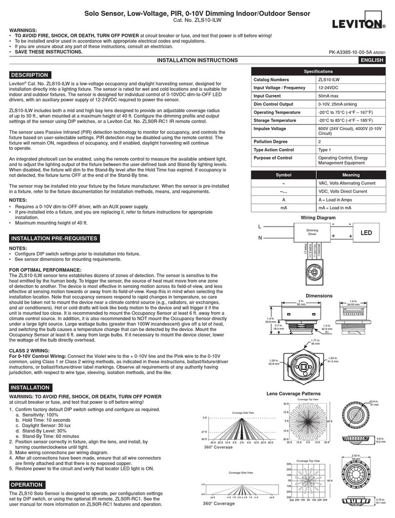
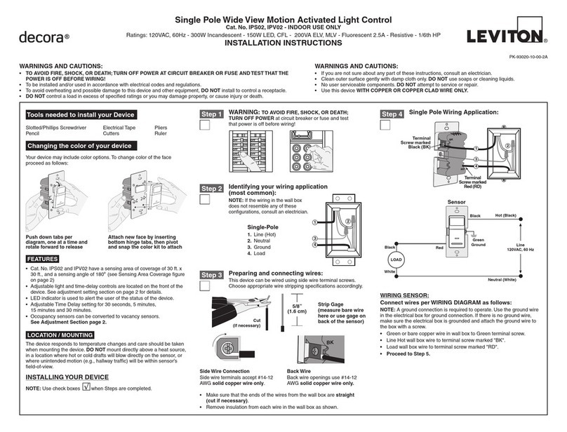
Wiring Diagram
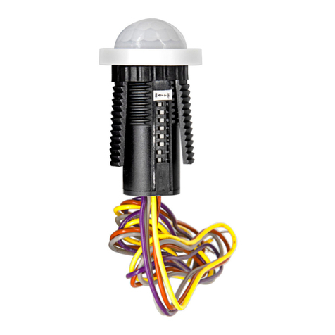
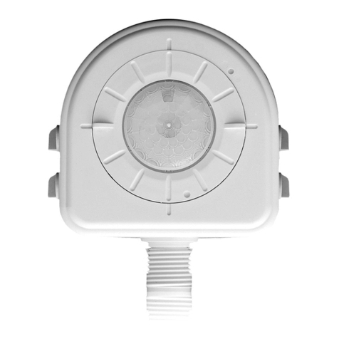
Leviton®Cat. No. ZLS10-IDW is a line voltage occupancy and daylight harvesting sensor, designed for installation
directly into a lighting fixture. The sensor is rated for wet and cold locations and is suitable for indoor and outdoor
fixtures. The sensor is designed for individual dimming control of 0-10VDC dim-to-OFF LED drivers or electronic
ballasts, or switching of non-dimming ballasts.
ZLS10-IDW includes both a mid and high bay lens, designed to provide an adjustable coverage radius of up to 30 ft.,
when mounted at a maximum height of 40 ft. Configure the dimming profile and output settings of the sensor using
DIP switches or a Leviton Cat. No. ZLS0R-RC1 IR remote control.
The sensor uses Passive Infrared (PIR) detection technology to monitor for occupancy, and controls the fixture based
on user-selectable settings. PIR detection may be disabled using the remote control. The fixture will remain ON
regardless of occupancy, and if enabled, daylight harvesting will continue to operate.
An integrated photocell can be enabled, using the remote control to measure the available ambient light and adjust
the lighting output of the fixture between user-defined task and Stand-By lighting levels. When disabled, the fixture
will dim to the Stand-By level after the Hold Time has expired. If occupancy is not detected, the fixture will turn OFF at
the end of the Stand-By time.
The sensor may be installed into your fixture by the fixture manufacturer. When the sensor is pre-installed in a fixture,
refer to the fixture documentation for installation methods, means, and requirements.
Symbol Meaning
~VAC, Volts Alternating Current
--… VDC, Volts Direct Current
A A = Load in Amps
mA mA = Load in mA
INSTALLATION PRE-REQUISITES
NOTES:
• Configure DIP switch settings prior to installation into fixture.
• See sensor dimensions for mounting requirements.
FOR OPTIMAL PERFORMANCE:
The ZLS10-IDW sensor lens establishes dozens of zones of detection. The sensor is sensitive to the heat emitted by
the human body. In order to trigger the sensor, the source of heat must move from one zone of detection to another.
The device is most effective in sensing motion across its field-of-view, and less effective in sensing motion towards
or away from its field-of-view. Keep this in mind when selecting the installation location. Note that occupancy sensors
respond to rapid changes in temperature, so care should be taken not to mount the device near a climate control
source (e.g., radiators, air exchanges, and air conditioners). Hot or cold drafts will look like body motion to the device,
and will trigger it if the unit is mounted too close. It is recommended to mount the Occupancy Sensor at least 6 ft.
away from a climate control source. In addition, it is also recommended to NOT mount the Occupancy Sensor directly
under a large light source. Large wattage bulbs (greater than 100W incandescent) give off a lot of heat, and switching
the bulb causes a temperature change that can be detected by the device. Mount the Occupancy Sensor at least 6 ft.
away from large bulbs. If it necessary to mount the device closer, lower the wattage of the bulb directly overhead.
CLASS 2 WIRING:
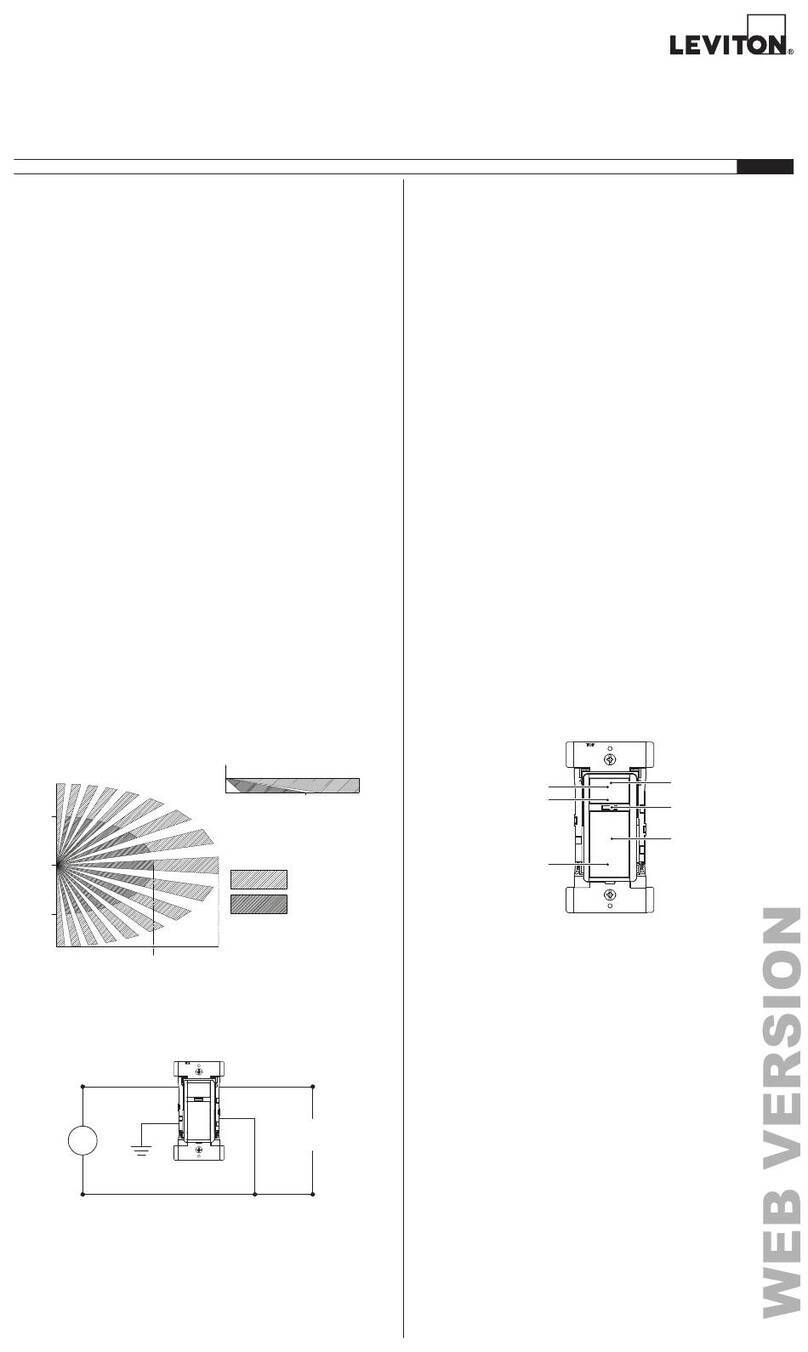
For 0-10V Control Wiring: Connect the Violet wire to the + 0-10V line and the Pink wire to the 0-10V common, using
Class 1 or Class 2 wiring methods, as indicated in these instructions, ballast/fixture/driver instructions, or ballast/
fixture/driver label markings. Observe all requirements of any authority having jurisdiction, with respect
to wire type, sleeving, isolation methods, and the like.
PINK (-)
3.5 in.
90 mm 1.6 in.
41 mm
1.7 in.
42.30 mm
0.5 in.
12.70 mm
0.7 in.
18.80 mm
3.2 in.
81.16 mm 1.4 in.
35.97 mm
2.4 in.
60.98 mm
1.3 in.
32.9 mm
G1
Dimensions
ZLS10-IDW
7LJKWHQLQJ
7LJKWHQLQJ H
DOO
DOO
H
DOO
0.2 in. (minimum)
Driver
ZLS10-IDW
7KU
Installation Diagram 1
Installation Diagram 2
PK-A3384-10-00-5A AR2561
FOR CANADA ONLY
For warranty information and/or product returns, residents of Canada should contact Leviton in writing
at Leviton Manufacturing of Canada ULC to the attention of the Quality Assurance Department,
165 Hymus Blvd, Pointe-Claire (Quebec), Canada H9R 1E9 or by telephone at 1-800-405-5320.
LIMITED 5 YEAR WARRANTY AND EXCLUSIONS
Leviton warrants to the original consumer purchaser and not for the benefit of anyone else that this product at the time of its sale by Leviton is free of defects in materials and workmanship under normal and proper
use for five years from the purchase date. Leviton’s only obligation is to correct such defects by repair or replacement, at its option. For details visit www.leviton.com or call 1-800-824-3005. This warranty
excludes and there is disclaimed liability for labor for removal of this product or reinstallation. This warranty is void if this product is installed improperly or in an improper environment, overloaded, misused,
opened, abused, or altered in any manner, or is not used under normal operating conditions or not in accordance with any labels or instructions. There are no other or implied warranties of any kind, including
merchantability and fitness for a particular purpose, but if any implied warranty is required by the applicable jurisdiction, the duration of any such implied warranty, including merchantability and fitness for a
particular purpose, is limited to five years. Leviton is not liable for incidental, indirect, special, or consequential damages, including without limitation, damage to, or loss of use of, any equipment,
lost sales or profits or delay or failure to perform this warranty obligation. The remedies provided herein are the exclusive remedies under this warranty, whether based on contract, tort or otherwise.
©2021 Leviton Mfg. Co., Inc.
IC STATEMENT:
This device complies with Industry Canada license-exempt RSS standard(s). Operation is subject to the
following two conditions: (1) this device may not cause interference, and (2) this device must accept any
interference, including interference that may cause undesired operation of the device.
CONFIGURATION
Use the DIP switches on the sensor, or the optional remote, ZLS0R-RC1, to set the
configuration parameters. See the user manual for more information on configuration,
using the remote.
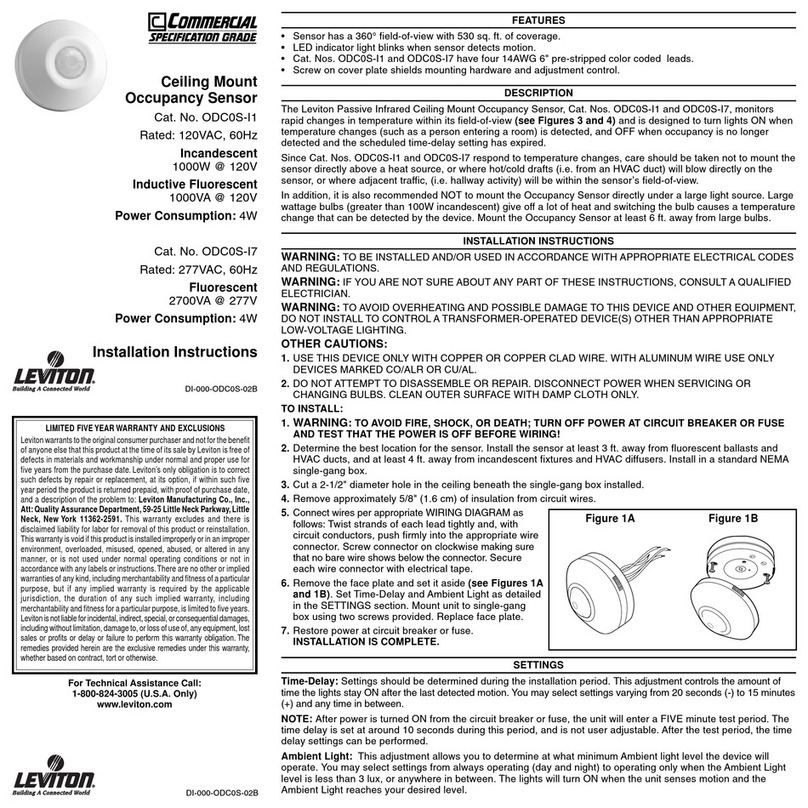
Configuration of the sensor using DIP switches on the device:
• DIP Switches 1 and 2 for Sensitivity / Range
• DIP Switches 3 and 4 for Hold Time / Timeout
• DIP Switches 5 and 6 for Daylight Sensor Lux Level
• DIP Switches 7 and 8 for Stand-By Level
• DIP Switches 9 and 10 for Stand-By Level Hold Time
1. Sensitivity / Range: Set the desired occupancy detection sensitivity.
3. Daylight Sensor Lux Level: Set or disable the desired Lux threshold, at which the
sensor will prevent the light from turning ON, when sufficient ambient light is present.
4. Stand-By Level: Set the desired level to which the light will dim after the Hold Time
expires.
For Technical Assistance, Call: 1-800-824-3005 (USA Only) or 1-800-405-5320 (Canada Only) www.leviton.com
FCC STATEMENT:
This equipment has been tested and found to comply with the limits for a Class B digital device, pursuant
to part 15 of the FCC Rules. These limits are designed to provide reasonable protection against harmful
interference in a residential installation. This equipment generates, uses and can radiate radio frequency
energy and, if not installed and used in accordance with the instructions, may cause harmful interference
to radio communications. However, there is no guarantee that interference will not occur in a particular
installation. If this equipment does cause harmful interference to radio or television reception, which can be
determined by turning the equipment off and on, the user is encouraged to try to correct the interference by
one or more of the following measures:
- Reorient or relocate the receiving antenna.
- Increase the separation between the equipment and receiver.
- Connect the equipment into an outlet on a circuit different from that to which the receiver is connected.
- Consult the dealer or an experienced radio/TV technician for help.
FCC SUPPLIERS DECLARATION OF CONFORMITY (SDOC):
Model ZLS10-IDW manufactured by Leviton Manufacturing Co., Inc., 201 North Service Road, Melville, NY
11747, http://www.leviton.com. This device complies with part 15 of the FCC Rules. Operation is subject to the
following two conditions: (1) This device may not cause harmful interference, and (2) this device must accept
any interference received, including interference that may cause undesired operation.
2. Hold Time / Timeout: Set the desired length of time that the light will remain ON
after occupancy is no longer detected.
5. Stand-By Time: Set the desired length of time that the light will remain at Stand-By
level. If +∞is selected, the light will remain at that level indefinitely, or until occupancy
is detected.
TROUBLESHOOTING
Lights will not turn ON.
• Sensor is wired incorrectly. Confirm that sensor wiring matches the wiring diagram,
and inspect it visually for problems.
• If daylight sensor is enabled, check settings and make adjustments to Lux levels.
Lights will not turn OFF.
• Sensor is wired incorrectly. Confirm that the sensor’s wiring is done correctly, and
inspect it visually for problems.
• Make sure the luminaire is installed with at least 1 ft. (30 cm.) of space between the
luminaire and surrounding reflective surfaces (e.g., metal, glass, or concrete walls).
• Sensitivity / Range is set improperly. Adjust DIP Switches 1 and 2.
Lights turn OFF and ON too quickly.
• Sensitivity / Range is set improperly. Adjust DIP Switches 1 and 2.
• Hold Time / Timeout is set improperly. Adjust DIP Switches 3 and 4.
This Class B digital apparatus complies with Canadian CAN ICES-3(B)/NMB-3(B).
1
1
0
0
SENSITIVITY
1 2
ON
OFF
50%
20%
75%
100%
SENSITIVITY
12
2.4 in.
61 mm
0.8 in.
19.2 mm
30 ft
30 ft 30 ft
60 ft
15 ft 15 ft0 ft
15 ft
15 ft
0 ft
0 ft
27 ft
40 ft
30 ft 30 ft20 ft 20 ft12 ft 12 ft6 ft 6 ft0 ft
30 ft
2.32 in.
59 mm
30ft
20ft
20ft
30ft
30ft
24 ft24 ft 11 ft11 ft 7 ft7 ft 3 ft3 ft 0
0 ft
8 ft
30ft
60 ft
20ft 20ft10ft 10ft0ft
10ft
0ft
10ft
0.75 in.
19.1 mm
ON
OF
F
TIME 3 4
1Min
10S
5Min
15Min
3
TIME
4
ON
OFF
LIGHT 5 6
10Lux
30Lux
50Lux
LIGHT
56
ON
OFF
STAND-BY LEVEL7 8
10%
0%
30%
50%
STAND-BY LEVEL
78
ON
OFF
STAND-BY TIME
910
1Min
+∞
30Min
60Min
STAND-BY TIME
910
Lens Coverage Patterns
OPERATION
The ZLS10 sensor is designed to operate per configuration settings set by DIP switch
or using the optional remote, ZLS0R-RC1. See user manual for more information on
ZLS0R-RC1 features and operation.
Any changes or modifications not expressly approved by Leviton could void the user’s
authority to operate this equipment.
Leviton
®
and the Leviton Logo are the registered trademarks of Leviton Manufacturing Co., Inc. Intellect
is a trademark of Leviton Manufacturing Co., Inc., registered in the U.S., Canada, Mexico, the EU, and the UK.
Other Leviton Security Sensor manuals

Leviton 61A00-1 Mounting instructions

Leviton

Leviton 61A00-1 Mounting instructions

Leviton ODC15-IDW User manual

Leviton

Leviton ODC15-IDW User manual

Leviton 47A00-2 User manual

Leviton

Leviton 47A00-2 User manual

Leviton ODSMT-MD User manual

Leviton

Leviton ODSMT-MD User manual

Leviton ZLS10-ILW User manual

Leviton

Leviton ZLS10-ILW User manual

Leviton decora IPV05 User manual

Leviton

Leviton decora IPV05 User manual

Leviton IPSD6 User manual

Leviton

Leviton IPSD6 User manual

Leviton DOS02 User manual

Leviton

Leviton DOS02 User manual

Leviton decora OSSMT-M3 User manual

Leviton

Leviton decora OSSMT-M3 User manual

Leviton Intellect Solo Sensor ZLS05-ILW User manual

Leviton

Leviton Intellect Solo Sensor ZLS05-ILW User manual

Leviton decora IPV02 User manual

Leviton

Leviton decora IPV02 User manual

Leviton ODC Series User manual

Leviton

Leviton ODC Series User manual

Leviton CRS4K User manual

Leviton

Leviton CRS4K User manual

Leviton HB011-PDX User manual

Leviton

Leviton HB011-PDX User manual

Leviton DECORA ODS15-IDI Series User manual

Leviton

Leviton DECORA ODS15-IDI Series User manual

Leviton GreenMAX OSR15-MCW User manual

Leviton

Leviton GreenMAX OSR15-MCW User manual

Leviton decora ODS10-TD Series User manual

Leviton

Leviton decora ODS10-TD Series User manual

Leviton Provolt ODC10-UDW User manual

Leviton

Leviton Provolt ODC10-UDW User manual

Popular Security Sensor manuals by other brands

Abtech BOSUNS manual

Abtech

Abtech BOSUNS manual

C-LOGIC 620-MD instruction manual

C-LOGIC

C-LOGIC 620-MD instruction manual

Theben 201 9 290 installation manual

Theben

Theben 201 9 290 installation manual

bolid IP 212-31 DIP-31 Operation manual

bolid

bolid IP 212-31 DIP-31 Operation manual

DeFelsko PosiTest LPD instruction manual

DeFelsko

DeFelsko PosiTest LPD instruction manual

ooma AirDial quick start guide

ooma

ooma AirDial quick start guide

Vertiqual Engineering V33 Series instruction manual

Vertiqual Engineering

Vertiqual Engineering V33 Series instruction manual

brennenstuhl MD operating instructions

brennenstuhl

brennenstuhl MD operating instructions

Ryobi ESF5000 user manual

Ryobi

Ryobi ESF5000 user manual

V-TAC VT-81011 instruction manual

V-TAC

V-TAC VT-81011 instruction manual

SMC Networks PSE56 Series Operation manual

SMC Networks

SMC Networks PSE56 Series Operation manual

Gaurdall DT15-AM installation instructions

Gaurdall

Gaurdall DT15-AM installation instructions

Di-soric DCC 12 VHD 2 PS-B3-56-7 quick start guide

Di-soric

Di-soric DCC 12 VHD 2 PS-B3-56-7 quick start guide

Comunello Automation DART Installation and user manual

Comunello Automation

Comunello Automation DART Installation and user manual

LI-COR LI-210R instruction manual

LI-COR

LI-COR LI-210R instruction manual

Bruker LYNXEYE XE user manual

Bruker

Bruker LYNXEYE XE user manual

Smanos MD9260 user manual

Smanos

Smanos MD9260 user manual

Delton 1000 quick start guide

Delton

Delton 1000 quick start guide

manuals.online logo
manuals.online logoBrands
  • About & Mission
  • Contact us
  • Privacy Policy
  • Terms and Conditions

Copyright 2025 Manuals.Online. All Rights Reserved.