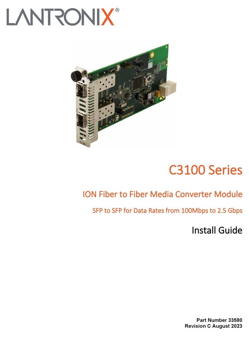
Lantronix ION C2110 User manual

ION C2110
ION Fast Ethernet Media Converter
100Base-TX to 100Base-FX
Install Guide
Part Number 33415
Revision C August 2023

Lantronix C2110 Install Guide
33415 Rev. C https://www.lantronix.com Page 2 of 24
Intellectual Property
© 2022, 2023 Lantronix, Inc. All rights reserved. No part of the contents of this publication may be
transmitted or reproduced in any form or by any means without the written permission of Lantronix.
Lantronix is a registered trademark of Lantronix, Inc. in the United States and other countries.
All other trademarks and trade names are the property of their respective holders.
Patented: https://www.lantronix.com/legal/patents/; additional patents pending.
Warranty
For details on the Lantronix warranty policy, go to http://www.lantronix.com/support/warranty.
Contacts
Lantronix Corporate Headquarters
48 Discovery, Suite 250
Irvine, CA 92618, USA
Toll Free: 800-526-8766
Phone: 949-453-3990
Fax: 949-453-3995
Technical Support
Online: https://www.lantronix.com/technical-support/
Sales Offices
For a current list of our domestic and international sales offices, go to www.lantronix.com/about/contact.
Disclaimer
All information contained herein is provided “AS IS.” Lantronix undertakes no obligation to update the
information in this publication. Lantronix does not make, and specifically disclaims, all warranties of any
kind (express, implied or otherwise) regarding title, non-infringement, fitness, quality, accuracy,
completeness, usefulness, suitability or performance of the information provided herein. Lantronix shall
have no liability whatsoever to any user for any damages, losses and causes of action (whether in
contract or in tort or otherwise) in connection with the user’s access or usage of any of the information or
content contained herein. The information and specifications contained in this document are subject to
change without notice.
Revision History
Rev
Date
Description
A
08/12/10
Initial release.
B
02/02/15
Update Specs, Jumper and DIP switch information and change formats.
C 8/31/23
Add max frame size, delete discontinued products, and update contact information.
Initial Lantronix re-brand. FW v 1.2.0: add note on DIP switches. Add minor editorial and
technical changes. FW v 2.0.0 add fix for determining the slot ID on the ION chassis.

Lantronix C2110 Install Guide
33415 Rev. C https://www.lantronix.com Page 3 of 24
Contents
Revision History ............................................................................................................................................ 2
Product Description....................................................................................................................................... 5
Ordering Information ..................................................................................................................................... 5
Features ........................................................................................................................................................ 5
Manageable Features ................................................................................................................................... 5
Distances....................................................................................................................................................... 6
Applications ................................................................................................................................................... 6
Installation ..................................................................................................................................................... 7
Configuration DIP Switches and Jumpers .................................................................................................... 7
Set the 4-position DIP Switch (SW1) ..................................................................................................... 8
Set AutoCross (E/D 3-Pin Jumper) (J4)................................................................................................. 9
Set Hardware / Software (H/S 3-Pin Jumper) (J5) ................................................................................ 9
J6: E/H 3-Pin Jumper (Do Not Alter) ........................................................................................................... 10
Install the C2110 in the ION Chassis .......................................................................................................... 11
Connect the Fiber Cable ............................................................................................................................. 11
Connect the Twisted-Pair Copper Cable .................................................................................................... 12
Operation..................................................................................................................................................... 12
Status LEDs ................................................................................................................................................ 12
Product Features......................................................................................................................................... 13
Auto-Negotiation ......................................................................................................................................... 13
Half-duplex Network (512-Bit Rule) ............................................................................................................ 13
Full-Duplex Network.................................................................................................................................... 13
Pause Control Frame .................................................................................................................................. 13
Link Pass-Through (LPT) ............................................................................................................................ 14
Far-End Fault (FEF) .................................................................................................................................... 14
SNMP .......................................................................................................................................................... 15
Cable Specifications.................................................................................................................................... 16
Fiber Cable Specs....................................................................................................................................... 16
Copper Cable Specs ................................................................................................................................... 17
Technical Specifications.............................................................................................................................. 18
PCB Revision Examples ............................................................................................................................. 19
PCB 11348 Rev. 01 .................................................................................................................................... 19
PCB 11348 Rev. A ...................................................................................................................................... 19
PCB 11322 Rev. 02 .................................................................................................................................... 20
PCB 11322 Rev. A ...................................................................................................................................... 20

Lantronix C2110 Install Guide
33415 Rev. C https://www.lantronix.com Page 4 of 24
Troubleshooting .......................................................................................................................................... 21
Compliance Information .............................................................................................................................. 22
FCC Regulations ......................................................................................................................................... 22
Canadian Regulations................................................................................................................................. 22
Declaration of Conformity............................................................................................................................ 23

Lantronix C2110 Install Guide
33415 Rev. C https://www.lantronix.com Page 5 of 24
Product Description
The ION C2110 is a media converter module that provides an interface between 100Base-TX ports and
100Base-FX ports, allowing users to integrate fiber optic cabling into 100Base-TX copper environments.
Operating at Layer 1, the physical layer, data is passed through the converter at line speed, making it
ideal for applications where low latency is essential. The ION C2110 is a manageable device when
installed in a managed ION chassis.
Note: Some Documentation may have Transition Networks named or pictured. Transition Networks was
acquired by Lantronix in August 2021.
Ordering Information
C2110-1011: 100BASE-TX (RJ-45) [100 m/328 ft.] to 100BASE-FX 1300nm MM (ST) [2 km/1.2 mi.] Link
Budget: 11.0 dB
C2110-1013: 100BASE-TX (RJ-45) [100 m/328 ft.] to 100BASE-FX 1300nm MM (SC) [2 km/1.2 mi.] Link
Budget: 11.0 dB
C2110-1039: 100BASE-TX (RJ-45) [100 m/328 ft.] to 100BASE-FX 1300nm MM (LC) [2 km/1.2 mi.] Link
Budget: 11.0 dB
C2110-1014: 100BASE-TX (RJ-45) [100 m/328 ft.] to 100BASE-FX 1300nm SM (SC) [20 km/12.4 mi.]
Link Budget: 16.0 dB
C2110-1019: 100BASE-TX (RJ-45) [100 m/328 ft.] to 100BASE-FX 1300nm SM (LC) [20 km/12.4 mi.]
Link Budget: 17.3 dB
C2110-1040: 100BASE-TX (RJ-45) [100 m/328 ft.] to 100Base-X SFP Slot (empty)
Features
•Auto-Negotiation of speed and duplex on TP port
•Auto-MDI/MDIX on TP port
•Link Pass Through (LPT)
•Far-End-Fault (FEF) detection
•Automatic Link Restoration
•Pause advertisement
•Field Upgradeable Firmware
•Can be used in any ION Platform Chassis
•Standards based, will link with any Standard 100Base-TX and any Standard 100Base-FX ports
Manageable Features
•Report converter status to chassis management software:
oTP and Fiber Link Status
oHardware switch settings
oCopper Port Speed
oTP and Fiber Port Duplex
oFault condition
•Write operation includes:
oPower on/off device
oAuto-Negotiation enable/disable
oForce 10 Mbps or 100 Mbps
oForce half or full-duplex
oSelect advertising modes when Auto-Negotiation is enabled

Lantronix C2110 Install Guide
33415 Rev. C https://www.lantronix.com Page 6 of 24
oLPT enable/disable
oFEF enable/disable
oPause enable/disable
oAuto-MDI/MDIX enable/disable
Note: Manageable Features are available when used in an ION Platform chassis along with an ION
Management Module.
Distances
Part Port 1 - Copper Port 2 - Duplex Fiber-Optic
Number 10/100/1000Base-T 100Base-FX
C2110-1011 RJ-45 100 m (328 ft) ST, 1300nm multimode, 2 km (1.2 miles) *
C2110-1013 RJ-45 100 m (328 ft) SC, 1300nm multimode, 2 km (1.2 miles) *
C2110-1014 RJ-45 100 m (328 ft) SC, 1300nm single mode, 20 km (12.4 miles) *
C2110-1019 RJ-45 100 m (328 ft) LC, 1300nm single mode, 20km (12.4 miles) *
C2110-1039 RJ-45 100 m (328 ft) LC, 1300nm multimode, 2km (1.2miles) *
C2110-1040 RJ-45 100 m (328 ft) SFP slot (empty)
* Typical max. cable distance. Actual distance depends on network installation physical characteristics.
Other transmission distances can be achieved with an open SFP converter (C2110-1040) and the
appropriate SFP module to match your required fiber type and transmission distance.
Applications
Fiber Integration in 10/100 Copper Environments: The ION C2110 device provides an interface
between 100Base-TX ports and 100Base-FX ports allowing users to integrate fiber optic cabling into
100Base-TX copper environments.

Lantronix C2110 Install Guide
33415 Rev. C https://www.lantronix.com Page 7 of 24
Installation
CAUTION: Wear a grounding device and observe electrostatic discharge precautions when setting the
4-position DIP switch and the jumpers. Failure to observe this caution could result in C2110 failure or
damage.
Configuration DIP Switches and Jumpers
PCB # 11322 Rev. x (this information is silkscreened in the center right side of the PCB as shown below).
Note that PCB layout and components can vary by revision.

Lantronix C2110 Install Guide
33415 Rev. C https://www.lantronix.com Page 8 of 24
Set the 4-position DIP Switch (SW1)
The 4-position DIP switch is located on the edge of the printed circuit board (PCB). Use a small flatblade
screwdriver to set the recessed switches. The default setting is all Up (Enabled).
SW1
Sw #
Function Settings
1 Auto-Negotiation
Up = Enabled: Advertises 100 Mb/s Full-Duplex and Half-Duplex
(only during Auto-Negotiation).
Down = Disabled: Disables Auto-Negotiation. Operates at 100
Mb/s in the mode (either full- or half-duplex) of the attached device.
2 Pause
Applies ONLY if switch “1” is Up (and the C2110 is connected to
auto negotiating device(s) capable of pause control frame.
Up = Enabled: Allows negotiation of pause control frame.
Down = Disabled: Does not allow negotiation of pause control
frame.
3 Link Pass Through
(LPT)
Up = Enabled: Enables Link Pass-Through.
Down = Disabled: Disables Link Pass-Through.
4 Far End Fault
(FEF)
Up = Enabled: Enables Far-End Fault.
Down = Disabled: Disables Far-End Fault.
Note that PCB layout and components can vary by revision.
Note: Fixes at FW v 1.2.0: while in hardware mode, only the DIP switches can be used to set product
configuration. The software management interface will only display current operating and configuration
status. Changes to the products configuration can no longer be set via software, while in hardware-mode.
See the online Release Notes for more information.

Lantronix C2110 Install Guide
33415 Rev. C https://www.lantronix.com Page 9 of 24
Set AutoCross (E/D 3-Pin Jumper) (J4)
When the AutoCross feature is enabled, it allows either straight-through or crossover cables to be used
when connecting to 100Base-TX devices. AutoCross determines the characteristics of the connection and
automatically configures the unit to link up, regardless of the cable configuration. Note: AutoCross is
enabled by default. Lantronix recommends leaving jumper J4 in the “Enabled” position.
The 3-pin header J4 for the jumper is located on the PCB and is labeled “E” (Enabled) and “D” (Disabled).
The default is E(Enabled). Use a small needle-nose pliers to remove and position the jumper.
The J4 settings are shown and described below:
E- Enable: the C2110 connects automatically to either straight-through or crossover twisted-pair copper
cable.
D- Disable: either straight-through or crossover twisted pair copper cable must be installed, according to
site requirements.
Set Hardware / Software (H/S 3-Pin Jumper) (J5)
The 3-pin header J6 for the jumper is located on the PCB and is labeled “H” (Hardware mode) and “S”
(Software) mode. Use a small needle-nose pliers to remove and position the jumper.
The J5 settings are shown and described below:
H- Hardware: C2110 mode is determined by the 4-position DIP switch (SW1) settings (see above).
The default is Hardware mode.
S- Software: C2110 mode is determined by the most recently saved on-board ION software settings.

Lantronix C2110 Install Guide
33415 Rev. C https://www.lantronix.com Page 10 of 24
J6: E/H 3-Pin Jumper (Do Not Alter)
The default setting is “E” (Ethernet). Do not change this setting.
E - Ethernet: Ethernet mode of operation (Default - Leave as is).
H - HSTR: High Speed Token Ring mode. Do not use this setting.
Note that PCB layout and components can vary by revision.

Lantronix C2110 Install Guide
33415 Rev. C https://www.lantronix.com Page 11 of 24
Install the C2110 in the ION Chassis
CAUTION: Wear a grounding device and observe electrostatic discharge precautions when installing the
C2110. Failure to observe this caution could result in damage or failure of the C2110.
1. Carefully slide the C2110 into an open ION chassis slot, aligning it with the slot guides.
2. Ensure that the C2110 is firmly seated into the slot.
3. Push in and rotate the attached panel Fastener clockwise to secure the C2110 to the ION chassis.
Connect the Fiber Cable
1. Locate a 100Base-FX compliant fiber cable with a male, two-stranded TX to RX connector
installed at each end.
2. Connect the fiber cables to the C2110 as described below:
•Connect the male TX cable connector to the female TX port.
•Connect the male RX cable connector to the female RX port.
3. Connect the fiber cables to the other device (another C2110, hub, etc.) as described below:
•Connect the male TX cable connector to the female RX port.
•Connect the male RX cable connector to the female TX port.

Lantronix C2110 Install Guide
33415 Rev. C https://www.lantronix.com Page 12 of 24
Connect the Twisted-Pair Copper Cable
1. Locate a 100Base-TX compliant cable, with a male RJ-45 connector installed at each end.
2. Connect the RJ-45 connector at one end of the cable to the RJ-45 port on the C2110.
3. Connect the RJ-45 connector at the other end of the cable to the RJ-45 port on the other device
(switch, workstation, etc.).
Operation
Status LEDs
The C2110 is designed to operate without user intervention. Use the status LEDs to
monitor the C2110 operation in the network.
PWR (Power): ON = Connection to powered ION Chassis backplane.
LKC (Copper Link): ON = Copper Link.
RXC (Receive Copper): Blinking = Data recieved on Copper link.
LKF (Fiber Link): ON = Fiber Link.
RFX (Receive Fiber): Blinking = Data received on Fiber Link.

Lantronix C2110 Install Guide
33415 Rev. C https://www.lantronix.com Page 13 of 24
Product Features
Auto-Negotiation
The Auto-Negotiation feature allows the C2110 to automatically configure itself to achieve the best
possible mode of operation over a link. The C2110 broadcasts its speed (100 Mb/s) and duplex
capabilities (full or half) to the other devices and negotiates the best mode of operation. Auto-Negotiation
allows quick and easy installation because the optimal link is established automatically. No user
intervention is required.
A scenario where the C2110 is linked to a non-negotiating device, disable Auto-Negotiation. In this
instance, the mode of operation will drop to the least common denominator between the two devices
(e.g., 100 Mb/s, half-duplex). Disabling this feature enables forcing the connection to the best mode of
operation.
Half-duplex Network (512-Bit Rule)
In a half-duplex network, the maximum cable lengths are determined by the round trip delay limitations of
each Fast Ethernet collision domain. (A collision domain is the longest path between any two terminal
devices, e.g., a terminal, switch, or router.)
The 512-Bit Rule determines the maximum length of cable permitted by calculating the round-trip delay in
bit-times (BTU) of a particular collision domain. If the result is less than or equal to 512 BTU, the path is
good.
Full-Duplex Network
In a full-duplex network, maximum cable lengths are determined by the type of cables used. See
“Ordering Information” on page 5for available C2110 models.
The 512-Bit Rule does not apply in a full-duplex network.
Pause Control Frame
The pause control feature can improve network performance by allowing one end of the link to signal the
other to discontinue frame transmission for a set period of time to relieve buffer congestion.
Note: If the pause control feature is present on all network devices attached to the C2110(s), enable the
pause control feature on the C2110(s). Otherwise, disable this feature.

Lantronix C2110 Install Guide
33415 Rev. C https://www.lantronix.com Page 14 of 24
Link Pass-Through (LPT)
When the Link Pass-Through feature is activated, it allows the C2110 to monitor both the fiber and copper
RX (receive) ports for loss of signal. In the event of a loss of an RX signal (1), the C2110 will
automatically disable the TX (transmit) signal (2), thus, “passing through” the link loss (3). The far-end
device is notified automatically of the link loss (4), which prevents the loss of valuable data transmitted
unknowingly over an invalid link.
Far-End Fault (FEF)
When a fault occurs on an incoming fiber link (1), the C2110 transmits a Far-End Fault signal on the
outgoing fiber link (2). In addition, the Far-End Fault signal also activates the Link Pass-Through, which in
turn disables the link on the copper portion of the network (3) and (4).

Lantronix C2110 Install Guide
33415 Rev. C https://www.lantronix.com Page 15 of 24
SNMP
See the on-line documentation that comes with Lantronix FocalPoint™or ION software for applicable
commands and usage.
Use SNMP at an attached terminal or at a remote location to monitor the following C2110 activities:
•Media-converter power
•Copper link status and fiber link status
•Twisted-pair cable length
•Hardware switch settings
•Fault condition
Also, use SNMP to enter network commands that:
•Enable/disable Auto-Negotiation
•Enable/disable Link Pass-Through (LPT)
•Enable/disable Far-End Fault (FEF)
•Enable/disable Pause
•Enable/disable AutoCross
•Power down the C2110

Lantronix C2110 Install Guide
33415 Rev. C https://www.lantronix.com Page 16 of 24
Cable Specifications
The physical characteristics must meet or exceed IEEE 802.3™ specifications.
Fiber Cable Specs
The fiber optic transmitters on this device meet Class I Laser safety requirements per IEC-825/CDRH
standards and comply with 21 CFR1040.10 and 21CFR1040.11.
Bit Error Rate: <10-9
Single mode fiber (recommended): 9 μm
Multimode fiber (recommended): 62.5/125 μm
Multimode fiber (optional): 50/125 μm
C2110-1011 1300 nm multimode
Fiber Optic Transmitter Power: min: -19.0 dBm max: -14.0 dBm
Fiber Optic Receiver Sensitivity: min: -30.0 dBm max: -14.0 dBm
Link Budget: 11.0 dB
C2110-1013 1300 nm multimode
Fiber Optic Transmitter Power: min: -19.0 dBm max: -14.0 dBm
Fiber Optic Receiver Sensitivity: min: -30.0 dBm max: -14.0 dBm
Link Budget: 11.0 dB
C2110-1014 1300 nm single mode
Fiber-optic Transmitter Power: min: -15.0 dBm max: -8.0 dBm
Fiber-optic Receiver Sensitivity: min: -31.0 dBm max: -8.0 dBm
Link Budget: 16.0 dB
C2110-1039 1300nm multimode
Fiber-optic Transmitter Power: min: -19 dBm max: -14.0 dBm
Fiber-optic Receiver Sensitivity: min: -30 dBm max: -14.0 dBm
Link Budget: 11 dB
C2110-1029-A1 1310nm TX/1550nm RX single mode
C2110-1029-A2 1550nm TX/1310nm RX single mode
Fiber Optic Transmitter Power: min: -14.0 dBm max: -8.0 dBm
Fiber Optic Receiver Sensitivity: min: -33.0 dBm max: -3.0 dBm
Link Budget: 19.0 dB

Lantronix C2110 Install Guide
33415 Rev. C https://www.lantronix.com Page 17 of 24
Copper Cable Specs
Category 5: (minimum requirement)
Gauge: 24 to 22 AWG
Attenuation: 22.0 dB /100m @ 100 MHz
Maximum Cable Distance: 100 meters
•Straight-through or crossover twisted-pair cable may be used.
•Shielded twisted-pair or unshielded twisted-pair may be used.
•Pins 1&2 and 3&6 are the two active pairs in an Ethernet network.
•Use only dedicated wire pairs for the active pins (e.g., blue/white & white/blue, orange/white &
white/orange, etc.)
•Do not use flat or silver satin wire.

Lantronix C2110 Install Guide
33415 Rev. C https://www.lantronix.com Page 18 of 24
Technical Specifications
For use with Lantronix Model C2110 or equivalent.
Standards: IEEE Std. 802.3
Data Rate: 100 Mbps, Layer-1
Max packet size 9K bytes
Dimensions: Width: 0.86” [22 mm] x Depth: 6.5” [165 mm] x Height: 3.4” [86 mm]
Shipping Weight: 1 lb (0.45 kg) approximately
Power Consumption: 2.5W-3.5W depending on the optic installed
MTBF: greater than 250,000 MIL-HDBK-217F hours
greater than 667,500 Bellcore hours
Environment: See chassis specifications
Storage Temp: -25 to 65°C (-13 to 149°F)
Humidity: 5 to 95%, non-condensing
Warranty: Lifetime
Regulatory Compliance: CISPR/EN55022 Class A, FCC Class A, CE Mark, NDAA Compliant, TAA
Compliant
The information in this user’s guide is subject to change.
This product is certified by the manufacturer to comply with DHHS Rule 21/CFR, Subchapter J applicable
at the date of manufacture.
CAUTION: Visible and invisible laser radiation when open. Do not stare into the beam or view directly
with optical instruments.
CAUTION: Use of controls, adjustments or the performance of procedures other than those specified
herein may result in hazardous radiation exposure.
CAUTION: Copper based media ports, e.g., Twisted Pair (TP) Ethernet, USB, RS232, RS422, RS485,
DS1, DS3, Video Coax, etc., are intended to be connected to intrabuilding (inside plant) link segments
that are not subject to lightening transients or power faults. Copper based media ports, e.g., Twisted Pair
(TP) Ethernet, USB, RS232, RS422, RS485, DS1, DS3, Video Coax, etc., are NOT to be connected to
interbuilding (outside plant) link segments that are subject to lightening transients or power faults. Failure
to observe this caution could result in damage to equipment.
Table of contents
Other Lantronix Media Converter manuals

Lantronix
Lantronix SI-IES-111D-LRT User manual

Lantronix
Lantronix C3210-10 Series User manual

Lantronix
Lantronix SGFEB Series User manual

Lantronix
Lantronix 4110 Series User manual

Lantronix
Lantronix ION C3110 User manual

Lantronix
Lantronix M/E-TX-FX Series User manual

Lantronix
Lantronix S3100 Series User manual

Lantronix
Lantronix ION C2210 User manual

Lantronix
Lantronix C3100 Series User manual

Lantronix
Lantronix M/GE-T 01 Series User manual