manuals.online logo
Brands
  1. Home
  2. •
  3. Brands
  4. •
  5. Danfoss
  6. •
  7. Controllers
  8. •
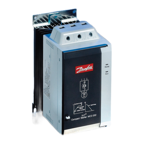
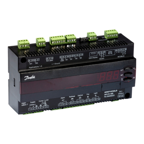
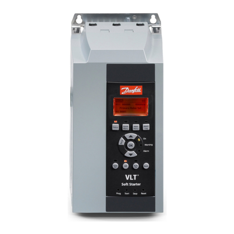
  9. Danfoss MCD 500 Series User manual

Danfoss MCD 500 Series User manual

MCD500 PCB Replacement MCD 500 PCB Replacement - Instructions
MI.17.F1.02 - VLT®is a registered Danfoss trademark Page 1/5
MCD 500 PCB Replacement - Instructions
Overview
This document describes how to replace the LCP (Local Control Panel) and main control PCB in MCD 500 soft
starters (all models).
N.B.!
Many electronic components are sensitive to static electricity. Voltages so low that they cannot be felt,
seen or heard, can reduce the life, affect performance, or completely destroy sensitive electronic
components. When performing service, proper ESD equipment should be used to prevent possible
damage from occurring.
Instructions
Remove all wiring and links from the soft starter before dismantling the unit. Disassemble the unit according
to the instructions below.
After reassembling the unit, apply control voltage and check that the welcome screen displays correctly.
1. Models MCD5-0021B ~ MCD5-0105B
Remove the top cover and terminal blocks from
the starter. Undo the 5 x Torx screws holding the
top plastic in place. Remove the top plastic.
Lift off the LCP and main control PCB assembly.
Label each SCR firing loom with the number of the
corresponding phase terminal on the main control
PCB, then unplug the looms. Unplug the
thermistor, fan (on selected models) and CT wires
from the main control PCB. Remove the existing
LCP and main control PCB and replace with the
new LCP/PCB.
Plug in the looms, replace 5 x Torx screws, top
cover and terminal plugs.
MCD 500 PCB Replacement - Instructions MCD500 PCB Replacement
MI.17.F1.02 - VLT®is a registered Danfoss trademark Page 2/5
2. Models MCD5-0131B ~ MCD5-0215B
Remove the top cover and terminal blocks from
the starter. Undo the 4 x Torx screws holding the
top plastic.
Tilt the top plastic to the right to expose the wiring
looms. Label each SCR firing loom with the number
of the corresponding phase terminal on the main
control PCB, then unplug the looms.
Unplug the thermistor, fan and CT wires from the
main control PCB. Undo the 4 x Torx screws from the model PCB
support bracket and set aside.
Remove 4 x Torx screws from the bypass driver
PCB, slide out to the right and set aside. Remove 7 x Torx screws from the main control PCB
and set aside.
Replace the PCBs, plug in the looms, top plastic,
top cover and terminal plugs.
MCD500 PCB Replacement MCD 500 PCB Replacement - Instructions
MI.17.F1.02 - VLT®is a registered Danfoss trademark Page 3/5
3. Model MCD5-0245C
Remove the top cover and terminal blocks from
the starter. Undo the 4 x Torx screws holding the
top plastic.
Tilt the top plastic to the right to expose the wiring
looms. Label each SCR firing loom with the number
of the corresponding phase terminal on the main
control PCB, then unplug the SCR firing looms
Unplug the thermistor, fan and CT wires from the
LCP and main control PCB and set the top plastic
aside.
Undo the 4 x Torx screws from the model PCB
support bracket and set aside.
Unplug the header connector from the main
control board and set aside.
Remove 7 x Torx screws. Replace the LCP and main
control PCB assembly. Replace the 7 x Torx screws
Replace the header connector. Replace the model board, check that the header
connector pins line up with the main control PCB
below.
MCD 500 PCB Replacement - Instructions MCD500 PCB Replacement
MI.17.F1.02 - VLT®is a registered Danfoss trademark Page 4/5
Reconnect the wiring looms. The SCR firing loom
will align with the relevant number of the
corresponding phase terminal on the main control
PCB. Take note of the thermistor wiring (grey/red)
to the right, and fan wiring (black/red) to the left
of the board. (The order of the thermistor and fan
plugs is not critical).
Replace the top plastic, top cover and terminal
plugs.
4. Models MCD5-0360C ~ MCD5-1600C
Remove the top cover and terminal blocks from
the starter. Undo the 4 x Torx screws holding the
top plastic.
Tilt the top plastic to the right to expose the wiring
looms. Label each SCR firing loom with the number
of the corresponding phase terminal on the main
control PCB assembly and unplug the SCR firing
looms.
Unplug the thermistor, fan and CT wires from the
LCP and main control PCB assembly. Undo the 4 x Torx screws from the model PCB
support bracket and set aside.
MCD500 PCB Replacement MCD 500 PCB Replacement - Instructions
MI.17.F1.02 - VLT®is a registered Danfoss trademark Page 5/5
Unplug the header connector from the main
control PCB and set aside. Remove 7 x Torx screws. Replace the LCP and main
control PCB assembly. Replace the 7 x Torx screws.
Replace the header connector.
Replace the model board, check that the header
connector pins line up with the main control PCB
below.
Replace the PCBs, plug in the looms, and replace
the LCP, top cover and terminal plugs. Take note
of the thermistor wiring (grey/red) to the right,
and fan wiring (black/red) to the left of the board.
Replace the 4 x Torx screws to secure the top
plastic and replace the top cover and terminal plugs.

This manual suits for next models

7

Other Danfoss Controllers manuals

Danfoss EKC 368 User manual

Danfoss

Danfoss EKC 368 User manual

Danfoss A266 Series Installation instructions manual

Danfoss

Danfoss A266 Series Installation instructions manual

Danfoss ERC 112D VSC User manual

Danfoss

Danfoss ERC 112D VSC User manual

Danfoss 101N0715 User manual

Danfoss

Danfoss 101N0715 User manual

Danfoss EKC 414A User manual

Danfoss

Danfoss EKC 414A User manual

Danfoss AME 120 NLX-1 User manual

Danfoss

Danfoss AME 120 NLX-1 User manual

Danfoss FP975 User manual

Danfoss

Danfoss FP975 User manual

Danfoss AFPQ 2 User manual

Danfoss

Danfoss AFPQ 2 User manual

Danfoss PN 16 User manual

Danfoss

Danfoss PN 16 User manual

Danfoss AMV 110 NL AQT User manual

Danfoss

Danfoss AMV 110 NL AQT User manual

Danfoss VLT HVAC Drive FC 102 User manual

Danfoss

Danfoss VLT HVAC Drive FC 102 User manual

Danfoss FC 300 User manual

Danfoss

Danfoss FC 300 User manual

Danfoss MCI 3 User manual

Danfoss

Danfoss MCI 3 User manual

Danfoss AME 855 User manual

Danfoss

Danfoss AME 855 User manual

Danfoss 140F1089 User manual

Danfoss

Danfoss 140F1089 User manual

Danfoss ICAD 600A User manual

Danfoss

Danfoss ICAD 600A User manual

Danfoss VLT MCD 201 User manual

Danfoss

Danfoss VLT MCD 201 User manual

Danfoss ERC 211 User manual

Danfoss

Danfoss ERC 211 User manual

Danfoss EKC 202A User manual

Danfoss

Danfoss EKC 202A User manual

Danfoss AK-PC 530 User manual

Danfoss

Danfoss AK-PC 530 User manual
Danfoss ECL Comfort 110 User manual

Danfoss

Danfoss ECL Comfort 110 User manual

Danfoss ECL Comfort 296 User manual

Danfoss

Danfoss ECL Comfort 296 User manual

Danfoss ERC 213 User manual

Danfoss

Danfoss ERC 213 User manual

Danfoss AMV 130 User manual

Danfoss

Danfoss AMV 130 User manual
Popular Controllers manuals by other brands

Epever MPPT user manual

Epever

Epever MPPT user manual

Dynamatic 4000 instruction sheet

Dynamatic

Dynamatic 4000 instruction sheet

Advantech B+B SmartWorx Wzzard BB-WSK-NRG-1 Setup manual

Advantech

Advantech B+B SmartWorx Wzzard BB-WSK-NRG-1 Setup manual

Planar Dome Md2/PCI Developer's guide

Planar

Planar Dome Md2/PCI Developer's guide

YSD KZ55 user manual

YSD

YSD KZ55 user manual

Festo CECX-X-C1 Series manual

Festo

Festo CECX-X-C1 Series manual

TMS Lite High Current Series user manual

TMS Lite

TMS Lite High Current Series user manual

NAVITAS TAC 1.0 Installation & service manual

NAVITAS

NAVITAS TAC 1.0 Installation & service manual

BIGSTONE C500B-LCD instructions

BIGSTONE

BIGSTONE C500B-LCD instructions

ABB RC/A 8.2 Mounting and operation instructions

ABB

ABB RC/A 8.2 Mounting and operation instructions

SMSC USB2242 datasheet

SMSC

SMSC USB2242 datasheet

Epson RC620 Series manual

Epson

Epson RC620 Series manual

GeoVision GV-AS200 quick start guide

GeoVision

GeoVision GV-AS200 quick start guide

LG MultiSITE VM3 Startup guide

LG

LG MultiSITE VM3 Startup guide

Shinko PCA1 instruction manual

Shinko

Shinko PCA1 instruction manual

ALLEN & HEATH iDR-4 Service information

ALLEN & HEATH

ALLEN & HEATH iDR-4 Service information

Novus N20K48 user guide

Novus

Novus N20K48 user guide

AMX AXB-VOL3 installation guide

AMX

AMX AXB-VOL3 installation guide

manuals.online logo
manuals.online logoBrands
  • About & Mission
  • Contact us
  • Privacy Policy
  • Terms and Conditions

Copyright 2025 Manuals.Online. All Rights Reserved.