manuals.online logo
Brands
  1. Home
  2. •
  3. Brands
  4. •
  5. Danfoss
  6. •
  7. Industrial Equipment
  8. •
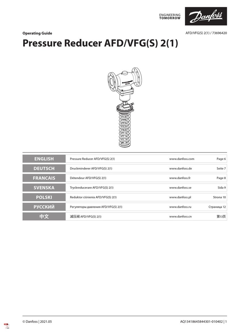
  9. Danfoss ICAD-UPS User manual

Danfoss ICAD-UPS User manual

Installation guide
ICAD-UPS for
ICM motor operated valves
027R9982
027R9982
© Danfoss | Climate solutions | 2022.04 AN394639594861en-000201 | 1
Info for UK customers only:Danfoss Ltd., 22 Wycombe End, HP9 1NB, GB
Імпортер:ТОВ з іі “Данфосс ТОВ”04080, Київ 80, п/с 168, Україна
1
2
4
3
6
5
7
120 mm
5 mm
138 mm
125 mm
4.7 in
50 mm
134 mm
268 mm
5 mm
10
60
1
10
20
Buer time
Time [min] Time[h]
01234567891011 12 13 14 15 16
Load [A]
2-
2+
1+
2-
2+
1+
B
A
A
2-
2+
1+
Press > 2 sec.
t
max
[min]
24 V 0.2 A
I < I
N
13 23 33
R1 R214 24 34
Stick
UPS
Stick
UPS
DC 24 V 10 A
OFF
ON
InputOutput
2
6
7
5
1
3
4
DC 24 V 10 A
Input Output
(Fig.9)
0.2 in 0.2 in
2 in
4.9 in
5.3 in
5.4 in
11 in
Custom
(Default 0.5)
ICAD-UPS dimensions/space requirements
Current output at power failure
Danfoss code no.: 027H0388
2-
2+
1+
2-
2+
1-
1+
Black
Black
120 mm
5 mm
138 mm
125 mm
4.7 in
50 mm
134 mm
268 mm
5 mm
10
60
1
10
20
Buer time
Time [min] Time[h]
01234567891011 12 13 14 15 16
Load [A]
2-
2+
1+
2-
2+
1+
B
A
A
2-
2+
1+
Press > 2 sec.
t
max
[min]
24 V 0.2 A
I < I
N
13 23 33
R1 R214 24 34
Stick
UPS
Stick
UPS
DC 24 V 10 A
OFF
ON
InputOutput
2
6
7
5
1
3
4
DC 24 V 10 A
Input Output
(Fig.9)
0.2 in 0.2 in
2 in
4.9 in
5.3 in
5.4 in
11 in
Custom
(Default 0.5)
120 mm
5 mm
138 mm
125 mm
4.7 in
50 mm
134 mm
268 mm
5 mm
10
60
1
10
20
Buer time
Time [min] Time[h]
01234567891011 12 13 14 15 16
Load [A]
2-
2+
1+
2-
2+
1+
B
A
A
2-
2+
1+
Press > 2 sec.
t
max
[min]
24V 0.2 A
I< I
N
13 23 33
R1 R214 24 34
Stick
UPS
Stick
UPS
DC 24 V 10 A
OFF
ON
InputOutput
2
6
7
5
1
3
4
DC 24 V 10 A
Input Output
(Fig.9)
0.2 in 0.2 in
2 in
4.9 in
5.3 in
5.4 in
11 in
Custom
(Default 0.5)
2-
2+
1+
2-
2+
1-
1+
Black
Black
1-
1+
2+
Buer time
© Danfoss | Climate solutions | 2022.04 AN394639594861en-000201 | 2
AWG
14-12
L
7
[Nm] [lb in]
0,5-0,6 5-7
Input DC
14-12
24-12
7
7
0,5-0,6
0,5-0,6
5-7
5-7
Output DC
Signals
[mm²]
0,2-2,5
[mm²]
0,2-2,5
0,2-2,5
0,2-2,5
0,2-2,5
0,2-2,5
13
23
33
14
24
34
R1
R2
Alarm
Bat.-
Mode
Bat.-
Charge
Remote
Confirm
Data-Port
Input
DC 24 V
Output
DC 24 V
24 V 0,2 A
I < I
N
t[min]
max
Battery
DC 24 V
0.3
[mm] [in]
0.3
0.3
13 23 33
14 24 34 R1 R2
24 V 0,2 A
I < I
N
+
-
+
-
CAD-U S
maximum 8 pcs. of ICAD 600 or maximum 3 pcs. of ICAD 1200
Input Output
Black
White
Brown
Black
White
Brown
+
-
+ -
DC 24 V
DC 24 V
+
-
CAD-U S
maximum 8 pcs. of ICAD 600 or maximum 3 pcs. of ICAD 1200
Input Output
Black
White
Brown
Black
White
Brown
+
-
+ -
DC 24 V
ICAD-UPS
ICAD-UPS
8
9 10
11
12
Shared 24 V DC Transformer for the
ICAD-UPS and ICAD 600/1200
Seperate 24 V DC Transformer for the
ICAD-UPS and ICAD 600/1200
Signal terminals
AWG
14-12
L
7
[Nm] [lb in]
0,5-0,6 5-7
Input DC
14-12
24-12
7
7
0,5-0,6
0,5-0,6
5-7
5-7
Output DC
Signals
[mm²]
0,2-2,5
[mm²]
0,2-2,5
0,2-2,5
0,2-2,5
0,2-2,5
0,2-2,5
13
23
33
14
24
34
R1
R2
Alarm
Bat.-
Mode
Bat.-
Charge
Remote
Confirm
Data-Port
Input
DC 24 V
Output
DC 24 V
24 V 0,2 A
I < I
N
t[min]
max
Battery
DC 24 V
0.3
[mm] [in]
0.3
0.3
13 23 33
14 24 34 R1 R2
24 V 0,2 A
I < I
N
+
-
+
-
CAD-U S
maximum 8 pcs. of ICAD 600 or maximum 3 pcs. of ICAD 1200
Input Output
Black
White
Brown
Black
White
Brown
+
-
+ -
DC 24 V
DC 24 V
+
-
CAD-U S
maximum 8 pcs. of ICAD 600 or maximum 3 pcs. of ICAD 1200
Input Output
Black
White
Brown
Black
White
Brown
+
-
+ -
DC 24 V
ICAD-UPS
ICAD-UPS
© Danfoss | Climate solutions | 2022.04 AN394639594861en-000201 | 3
Input data Battery charge
Nominal input voltage 24 V DC Status display Red/Green LED Bargraph
Input voltage range 18 V DC – 30 V DC Switching output Relay
(Preset: switching output - active high)
30 V AC/DC , ≤ 100 mA
Current consumption 14 A
Output data (mains operation) Signal supply
Nominal output voltage 24 V DC Switching voltage Buered ≤ 24 V DC 200 mA
Output voltage range (depending on the
input voltage) 18 V DC – 30 V DC Switching current Short-circuit-proof
Output current with convection cooling Remote control
Nominal output current Permanent
Power Boost
SFB technology 12 ms
10 A Version 1
Output R1 to input R2 Plug-in-bridge
15 A
60 A Version 2
Input R2
Input current R2
24 V DC
200 mA
Output data (battery operation)
Nominal output voltage 24 V DC
Output voltage range (depending on the
battery voltage)
19,2 V DC – 27,6 V DC
(UOUT = UBAT - 0,5 V DC) Energy storage
Output current with convection cooling Battery type Panasonic UP-VW1220P1
Memory medium Lead rechargeable
battery module, 3.4 Ah
Nominal voltage 24 V DC
End-of-charge voltage (temperature
compensated) 24 V DC – 29 V DC
Capacitance 3,4 Ah
Charging current ICHARGE 2,88 A
Battery service life 6 – 9 (20 °C)
Latest startup
Months 6 (0 °C – 20 °C)
Months 6 – 3 (20 °C – 30 °C)
Months 3 – 1 (30 °C – 40 °C)
General data
Degree of protection / Protection class IP20 / III
Degree of pollution 2
Ambient temperature (operation) 0 °C – 40 °C
Ambient temperature (storage/transport) -15 °C – 40 °C
Humidity at 25 °C, non-condensing ≤ 95 %
Dimensions (W/H/D) 120 x 169 x 125 mm
Weight 3,8 kg
Technical Data
Output current with convection cooling
Nominal output current Permanent
Power Boost
SFB technology 15 ms
10 A
15 A
65 A
Buer time (IOUT = ) 180 min. (1 A) / 10 min. (10 A)
Connection types
Connection in parallel Yes 2
Connection in series No
Signaling
Power In OK
Status display Green LED
Alarm
Status display Red
Switching output Relay
(Preset: switching output - active low)
LED
30 V AC/DC , ≤ 100 mA
Battery mode
Status display Yellow
Switching output Relay
(Preset: switching output - active high)
LED
30 V AC/DC , ≤ 100 mA
IN
IN
IN
UN
© Danfoss | Climate solutions | 2022.04 AN394639594861en-000201 | 4
ENGLISH
Uninterruptible power supply with integrated battery
ICAD-UPS is dedicated for use along with ICM sizes 20-150 installed
with ICAD 600A and ICAD 1200A actuators.
In the event of power failure, there is a need to make sure that the
ICM goes to a safe position.
Danfoss ICAD-UPS can be connected to the ICAD 600A / 1200A.
The solution ICM with ICAD connected to ICAD-UPS with default
speed and boost value (i30 and i31) will give one of the following
possibilities in the event of power failure:
– close ICM
– open ICM
– stay
– go to a specic ICM Opening Degree
When power supply has been re-established the system will
automatically return to normal operation.
The uninterruptible power supply (UPS) is equipped with an
integrated energy storage system. The internal energy storage
system is monitored continuously by the battery management
system.
Features
• UPS with integrated energy storage
• Integrated temperature sensor for optimized battery charging
• Energy storage system
Safety and warning instructions
Only professionals may install and start up the device. Regulations
specic to the country must be observed.
• Never carry out work on live parts
• Establish connection correctly and ensure protection against
electric shock
• Use a current-limited source or a suitable fuse (≤15 A)
• When connecting the individual battery blocks, ensure the
correct polarity and avoid short circuits on the pole terminals
• Following installation, cover the terminal area to prevent
accidental contact with live parts (e.g., installation in a control
cabinet)
• Observe mechanical and thermal limits
• The location must allow for sucient ventilation
• Keep ames, embers or sparks away from the module
• When changing the battery, use only battery blocks of the same
type with the same batch number
• The battery blocks are maintenance-free and may not be
opened
• When storing the UPS, pay attention to the latest startup date
of the battery set, and recharge the battery set if necessary
• Prior to transporting the UPS, remove the DC fuse in the battery
compartment
• Do not disconnect the DC fuse and/or the battery wiring under
Hazloc conditions
Initial charging of the battery
Prior to starting the UPS up in your application, connect the
UPS to a voltage source and charge the battery set for
24 hours.
1. Designation of the elements (g. 7)
1. Connection terminal blocks for signals
2. Status indicators/IFS interface/Selector switch
(Activation threshold)
3. Connection terminal blocks for DC input
4. Connection terminal blocks for DC outputs
5. Internal DC fuse (batteries)
6. Battery set (2 battery blocks)
7. Battery connecting cables (polarity- and color-coded)
1.1 LED status indicators/LED bar graph
The UPS status is displayed via LEDs in dierent colors and ash
sequences.
The oating switching outputs switch depending on the current
device status.
2. Opening/closing the battery compartment (g. 3)
• Press the locking buttons on the battery compartment
• Carefully remove the battery compartment cover
• You can now carry out the work to be done
• Then press the battery compartment cover onto the locking
latches
3. DCC fuse (g. 4)
The UPS is equipped with an internal pluggable DC fuse as
protection during transport and for protecting the cabling.
Always remove the DC fuse prior to transporting to the UPS.
To start up the UPS, plug the DC fuse back into the fuse
holder.
A faulty/blown DC fuse must be replaced by a fuse of the
same type.
4. Battery connecting cables (g. 6)
Check the battery wiring for the individual battery blocks
for the correct polarity and color coding.
508:
Use copper cables for operating temperatures of
> 75 °C (ambient temperature < 55 °C)
> 90 °C (ambient temperature < 75 °C)
60950:
Use ferrules for exible cables
Tighten screws on all unused terminals
A. Suitable for a max. altitude of 2000 m
B. Suitable for indoor use only
C. Clean only with water
D. Power source shall be double isolated from hazardous voltages
E. Protection may be impaired if the equipment is used in a manner
not specied by the manufacturer
F. This equipment is suitable for use in class I, Division 2, Groups A,
B, C and D or non-hazardous locations only
G. For all models the following end-product enclosures are
required: Mechanical, Fire, Electrical
H. Warning - Explosion hazard - Do not disconnect equipment
unless power has been removed or the area is known to be free
of ignitable concentrations
I. Note - Explosion hazard - Substitution of components may
impair suitability for use in potentially explosive areas
(CLASS 1; DIVISION 2)
J. Warning - Explosion hazard: Do not replace fuse unless power
has been switched o or the area is known to be
non-hazardous
K. Warning - Explosion hazard: Do not remove or replace battery
while the circuit is live or unless the area is known to be free of
ignitable concentrations
Notes on disposal
Do not dispose of used batteries in the household waste!
Dispose of these according to the currently valid national
regulations.
This manual suits for next models

1

Other Danfoss Industrial Equipment manuals

Danfoss XG 14 User manual

Danfoss

Danfoss XG 14 User manual

Danfoss iSave 40 User manual

Danfoss

Danfoss iSave 40 User manual

Danfoss VACON NX User guide

Danfoss

Danfoss VACON NX User guide

Danfoss VX Solo HWS User manual

Danfoss

Danfoss VX Solo HWS User manual

Danfoss AFA 2 / VFG 2 User manual

Danfoss

Danfoss AFA 2 / VFG 2 User manual

Danfoss iSave 40 User manual

Danfoss

Danfoss iSave 40 User manual

Danfoss BOCK HG44e User manual

Danfoss

Danfoss BOCK HG44e User manual

Danfoss BOCK FK40 User manual

Danfoss

Danfoss BOCK FK40 User manual

Danfoss 176F1784 User manual

Danfoss

Danfoss 176F1784 User manual

Danfoss EC-LTS1200-410 User manual

Danfoss

Danfoss EC-LTS1200-410 User manual

Danfoss PVG 32 User guide

Danfoss

Danfoss PVG 32 User guide

Danfoss Airflex DBBS User manual

Danfoss

Danfoss Airflex DBBS User manual

Danfoss iSave 21 User manual

Danfoss

Danfoss iSave 21 User manual

Danfoss PLUS+1 JS1-H Instruction Manual

Danfoss

Danfoss PLUS+1 JS1-H Instruction Manual

Danfoss VLT Soft Starter MCD 600 User manual

Danfoss

Danfoss VLT Soft Starter MCD 600 User manual

Danfoss HG88e User manual

Danfoss

Danfoss HG88e User manual

Danfoss VLT Safety Option MCB 150 User manual

Danfoss

Danfoss VLT Safety Option MCB 150 User manual

Danfoss EvoFlat 4.0 M User manual

Danfoss

Danfoss EvoFlat 4.0 M User manual

Danfoss VLT HVAC Drive FC 102 User manual

Danfoss

Danfoss VLT HVAC Drive FC 102 User manual

Danfoss WS 403 User manual

Danfoss

Danfoss WS 403 User manual

Danfoss AFPA 2 / VFG 2 DN 15-250 User manual

Danfoss

Danfoss AFPA 2 / VFG 2 DN 15-250 User manual

Danfoss Optyma Slim Pack User manual

Danfoss

Danfoss Optyma Slim Pack User manual

Danfoss Kompakt H28 User manual

Danfoss

Danfoss Kompakt H28 User manual

Danfoss Aeroquip FT1370 User manual

Danfoss

Danfoss Aeroquip FT1370 User manual

Popular Industrial Equipment manuals by other brands

GE RAB8116B installation instructions

GE

GE RAB8116B installation instructions

Terex Genie Super Hoist Operator's manual

Terex

Terex Genie Super Hoist Operator's manual

ABB HT579397 Operation manual

ABB

ABB HT579397 Operation manual

FläktGroup EQRB Installation and maintenance instructions

FläktGroup

FläktGroup EQRB Installation and maintenance instructions

Toro 301 High Lift quick start guide

Toro

Toro 301 High Lift quick start guide

AHCON BBRT 700 Operator's manual

AHCON

AHCON BBRT 700 Operator's manual

morse M Series Installation and maintenance instructions

morse

morse M Series Installation and maintenance instructions

Eaton Power Xpert Gateway 900 Installation, operation & maintenance manual

Eaton

Eaton Power Xpert Gateway 900 Installation, operation & maintenance manual

Hussmann Purity Installation & operation manual

Hussmann

Hussmann Purity Installation & operation manual

riverhawk IM-257 instruction manual

riverhawk

riverhawk IM-257 instruction manual

Sun Microsystems Sun StorageTek SL24 User's and service guide

Sun Microsystems

Sun Microsystems Sun StorageTek SL24 User's and service guide

Siemens 3WN6 operating instructions

Siemens

Siemens 3WN6 operating instructions

TMG TMG-PC90 product manual

TMG

TMG TMG-PC90 product manual

WilTec 61546 Operation manual

WilTec

WilTec 61546 Operation manual

PCB Piezotronics ICP 320C20 Installation and operating manual

PCB Piezotronics

PCB Piezotronics ICP 320C20 Installation and operating manual

HYDAC International FluidAqua Mobil FAM 10 Additional instructions

HYDAC International

HYDAC International FluidAqua Mobil FAM 10 Additional instructions

Conductix-Wampfler Hevi-Bar II manual

Conductix-Wampfler

Conductix-Wampfler Hevi-Bar II manual

SCHUNK PZH Series operating manual

SCHUNK

SCHUNK PZH Series operating manual

manuals.online logo
manuals.online logoBrands
  • About & Mission
  • Contact us
  • Privacy Policy
  • Terms and Conditions

Copyright 2025 Manuals.Online. All Rights Reserved.