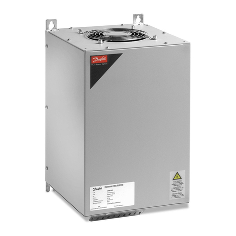
Danfoss VLT AAF006 User manual

MAKING MODERN LIVING POSSIBLE
VLT®Advanced Active Filter
AAF006 D and E Frame
Service Manual
www.danfoss.com/drives
*MG90Z122*
130R0268 MG90Z122 Rev. 2012-04-20

Contents
1 Introduction 1-1
1.1 VLT Active Filter Product Overview 1-1
1.2 For Your Safety 1-1
1.2.1 Warnings 1-1
1.3 Electrostatic Discharge (ESD) 1-1
1.4 Frame Size Definitions 1-2
1.5 Rating Tables 1-3
1.6 Fuses 1-4
1.7 Current Transducers 1-4
1.7.1 Current Transducers 1-4
1.8 General Torque Tightening Values 1-5
1.9 Tools Required 1-5
1.10 Exploded Views 1-6
1.10.1 Exploded Views E-Frame 1-6
2 Operator Interface and Active Filter Control 2-1
2.1 Introduction 2-1
2.2 User Interface 2-1
2.2.1 LCP Layout 2-1
2.2.2 Setting LCP Display Values 2-2
2.2.3 Display Menu Keys 2-2
2.2.4 Navigation Keys 2-3
2.2.5 Operation Keys 2-3
2.2.6 Tips and Tricks 2-4
2.3 Status Messages 2-4
2.3.1 Status Message Definitions 2-4
2.4 Service Functions 2-5
2.5 Filter Inputs and Outputs 2-5
2.5.1 Current Transformers 2-5
2.5.2 Filter CT Input 2-5
2.5.2.1 External CT Input 2-5
2.5.3 Control Wiring Input/Output 2-7
2.5.4 Serial Communication Wiring 2-7
2.5.5 Relay Options 2-8
2.6 Control Terminals 2-8
2.7 Control Terminal Functions 2-9
2.8 Grounding Shielded Control Cables 2-11
Contents VLT Advanced Active Filter AAF006 D and E Frames Service Manual
MG90Z122 - VLT®is a registered Danfoss trademark

3 Internal Active Filter Operation 3-1
3.1 General 3-1
3.2.2 Control Card 3-1
3.2.3 Active Filter Card 3-2
3.2.4 Control to Power Interface 3-2
3.2.5 Filter Power Section 3-3
3.3 Additional Circuitry 3-3
3.3.1 AC Contactor 3-3
3.3.2 Soft Charge Circuit 3-3
3.3.3 Additional Thermal Protection 3-4
3.3.4 Current Transducers 3-4
3.3.5 Cooling Fans 3-4
3.3.6 Fan Speed Control 3-4
3.3.7 Low Harmonic Drive 3-5
4 Troubleshooting 4-1
4.1 Troubleshooting Tips 4-1
4.2 Fault Symptom Troubleshooting 4-1
4.3 Visual Inspection 4-2
4.4 Fault Symptoms 4-3
4.4.1 No Display 4-3
4.4.2 Intermittent Display 4-3
4.5 Warning/Alarm Messages 4-4
4.5.1 Warning/Alarm Code List 4-4
4.6 After Repair Tests 4-12
5 Active Filter and the Power Grid 5-1
5.1 Grid Variations 5-1
5.1.1 Grid Configurations 5-1
5.1.2 Grid Impedance 5-1
5.1.3 Voltage Pre-distortions 5-1
5.2 Basic Troubleshooting Background 5-1
5.2.1 Line Phase Loss and Unbalanced Phase Trips 5-1
5.2.2 Voltage Dips and Flickers 5-1
5.2.3 Compatibility with Other Equipment on the Same Line Power 5-2
5.2.4 Line Power Resonances 5-2
5.2.5 Control Logic Problems 5-2
5.2.6 Programming Problems 5-3
Contents VLT Advanced Active Filter AAF006 D and E Frames Service Manual
MG90Z122 - VLT®is a registered Danfoss trademark

5.3 Internal Active Filter Problems 5-3
5.3.1 Overtemperature Faults 5-3
5.3.2 Current Feedback Problems 5-3
5.3.3 Noise On CT Input 5-4
5.3.4 Effect of EMI 5-4
6 Test Procedures 6-1
6.1 Introduction 6-1
6.1.1 Tools Required for Testing 6-2
6.1.2 Signal Test Board 6-2
6.2 Static Test Procedures 6-2
6.2.1 Inverter Section Tests 6-2
6.2.1.1 Inverter Test Part I 6-2
6.2.1.2 Inverter Test Part II 6-2
6.2.1.3 Inverter Test Part III 6-3
6.2.1.4 Inverter Test Part IV 6-3
6.2.2 Gate Resistor Test 6-3
6.2.3 Intermediate Section Tests 6-3
6.2.4 Heatsink Temperature Sensor Test 6-4
6.2.5 Fan Continuity Tests 6-4
6.2.5.1 Fan Fuse Test 6-4
6.2.5.2 Ohm Test of Transformer 6-4
6.2.5.3 Ohm Test of Fans 6-4
6.2.6 AC Line power Contactor and Soft Charge Contactor Tests 6-5
6.3 Dynamic Test Procedures 6-5
6.3.1 No Display Test 6-5
6.3.2 Input Voltage Test 6-5
6.3.3 Control Card Basic Voltage Test 6-6
6.3.4 Switch Mode Power Supply (SMPS) Test 6-6
6.3.5 Current Sensors Test CT1, CT2, CT3 6-7
6.3.6 Input Terminal Signal Tests 6-7
6.3.7 Line Power Resonance Test 6-8
6.3.8 Control Card Digital Inputs/Outputs Test 6-8
6.4 After Repair Tests 6-8
7 D-Frame Sizes Disassembly and Assembly Instructions 7-1
7.1 Electrostatic Discharge (ESD) 7-1
7.2 Passive Section (Top) Instructions 7-2
7.2.1 Control Card and Control Card Mounting Plate 7-3
Contents VLT Advanced Active Filter AAF006 D and E Frames Service Manual
MG90Z122 - VLT®is a registered Danfoss trademark

7.2.2 Control Assembly Support Bracket 7-3
7.2.3 Active Filter Card 7-3
7.2.4 Power Card 7-4
7.2.5 Power Card Mounting Plate 7-5
7.2.6 AC Capacitors 7-6
7.2.7 AC Capacitor Current Sensor (CT4, CT5, CT6) 7-7
7.2.8 AC Contactors 7-7
7.2.9 MOVs 7-8
7.2.10 Discharge Card 7-8
7.2.11 Soft Charge Resistor 7-8
7.3 Active Side (Bottom) Instructions 7-9
7.3.1 Input Terminal Mounting Plate 7-9
7.3.2 Gate Drive Card 7-11
7.3.3 Contactor Transformer 7-11
7.3.4 Common Mode (CM) RFI Filter Card 7-11
7.3.5 Differential Mode (DM) RFI Filter Card 7-12
7.3.6 Capacitor Bank Assembly 7-12
7.3.7 IGBT Modules 7-13
7.3.8 IGBT Current Sensors CT1, CT2, and CT3 7-14
7.3.9 Damping Resistors 7-14
7.3.10 Fan Transformer 7-14
7.3.11 Fan 7-14
8 E-Frame Sizes Disassembly and Assembly Instructions 8-1
8.1 Electrostatic Discharge (ESD) 8-1
8.2 Passive Section (Top) Instructions 8-2
8.2.1 Control Card and Control Card Mounting Plate 8-3
8.2.2 Control Assembly Support Bracket 8-3
8.2.3 Active Filter Card 8-3
8.2.4 Power Card 8-4
8.2.5 Power Card Mounting Plate 8-5
8.2.6 AC Capacitors 8-6
8.2.7 AC Capacitor Current Sensor (CT4, CT5, CT6) 8-7
8.2.8 AC Contactors 8-9
8.2.9 Common Mode (CM) RFI Filter Card 8-10
8.2.10 Differential Mode (DM) RFI Filter Card 8-10
8.2.11 MOVs 8-10
8.2.12 Discharge Card 8-10
Contents VLT Advanced Active Filter AAF006 D and E Frames Service Manual
MG90Z122 - VLT®is a registered Danfoss trademark

8.2.13 Soft Charge Resistor 8-10
8.3 Active Section (Bottom) Instructions 8-10
8.3.1 Input Terminal Mounting Plate 8-10
8.3.2 Gate Drive Card Mounting Plate 8-12
8.3.3 Gate Drive Card 8-12
8.3.4 Upper Capacitor Bank Assembly 8-13
8.3.5 Lower Capacitor Bank Assembly 8-14
8.3.6 IGBT Modules 8-15
8.3.7 IGBT Current Sensors CT1, CT2, and CT3 8-17
8.3.8 Fan Transformer 8-18
8.3.9 Fan 8-18
8.3.10 Damping Resistors 8-18
9 Special Test Equipment 9-1
9.1 Test Equipment 9-1
9.1.1 Signal Test Board (p/n 176F8437) 9-1
9.1.2 Signal Test Board Pin Outs: Description and Voltage Levels 9-1
Contents VLT Advanced Active Filter AAF006 D and E Frames Service Manual
MG90Z122 - VLT®is a registered Danfoss trademark

Contents VLT Advanced Active Filter AAF006 D and E Frames Service Manual
MG90Z122 - VLT®is a registered Danfoss trademark

1 Introduction
The purpose of this manual is to provide detailed technical
information and instructions to enable a qualified
technician to identify faults and perform repairs on VLT®
Advanced Active Filters in D- and E-frame sizes. It covers
both the stand alone active filter (AAF) and the filter
portion of the VLT®Low Harmonic Drive (LHD).
This manual provides the reader with a general view of the
filter's main assemblies and a description of the internal
processing. With this information, technicians should have
an understanding of AAF operation for troubleshooting
and repair.
This manual provides instructions for the active filter
models and voltage ranges described in Table 1.1.
1.1 VLT Active Filter Product Overview
VLT®Active Filter AAF006 is a device for harmonics and
reactive current mitigation. The unit is designed for instal-
lation in various applications or combined with a
Adjustable frequency drive as a packaged low harmonic
drive solution. The AAF measures the current signal via
external transducers and counteracts the unwanted
elements of the measured current. The unwanted elements
are programmable via the LCP. The active filter can
compensate all harmonics until 40th harmonics at the same
time in an overall compensation mode or until the 25th
harmonics individual selected down to specified value set
via the LCP. The unit is also capable of correcting reactive
currents to harmonize the current and voltage phases,
creating a displacement power factor close to 1. The AAF
also balances the current loads equally on all three phases.
1.2 For Your Safety
1.2.1 Warnings
CAUTION
Active filters contain dangerous voltages when connected
to line power. The connected current transducers may also
hold dangerous voltages when connected. Only a
competent technician should carry out service.
WARNING
For dynamic test procedures, line power is required and all
devices and power supplies connected to line power are
energized at rated voltage. Use extreme caution when
conducting tests in a powered unit. Contact with powered
components could result in electrical shock and personal
injury.
1. DO NOT touch electrical parts of the filter or
external current transducers when connected to
line power. After removing power from line
power, wait 20 minutes for D-frame and 40 for E-
frame units before touching any electrical parts.
2. When any repair or inspection is made, line
power must be disconnected.
3. The STOP key on the control panel does not
disconnect line power.
4. When servicing external current transformers
(CTs), remove power completely from the
connection point on both line power and
secondary side of the CTs.
5. Use a shorting connector on the secondary side
of customer-supplied external current
transformers (CTs) whenever current is present on
the line power (primary side) and the AFC card is
NOT wired to the external CT terminals.
1.3 Electrostatic Discharge (ESD)
CAUTION
When performing service, use proper ESD procedures to
prevent damage to sensitive components.
Many electronic components within the unit are sensitive
to static electricity. Voltages so low that they cannot be
easily detected can reduce the longevity and performance
of the AAF, or completely destroy sensitive electronic
components.
Introduction VLT Advanced Active Filter AAF006 D and E Frames Service Manual
MG90Z122 - VLT®is a registered Danfoss trademark 1-1
11
1.4 Frame Size Definitions
380–480 V AC
Active Filter current Associated LHD power range Frame designation Weight of unit
HO/NO (hp [kW]) Filter lbs [kg]
A190 D13 524.7 [238]
A250 E1 945.8 [429]
A310 E1 945.8 [429]
A400 E1 998.7 [453]
A120 175/225 [132/160] D14 676.8 [307]
A120 225/275 [160/200] D14 676.8 [307]
A120 275/350 [200/250] D14 676.8 [307]
A210 350/425 [250/315] E9 1490 [676]
A210 425/500 [315/355] E9 1490 [676]
A210 500/550 [355/400] E9 1490 [676]
A210 550/600 [400/450] E9 1490 [676]
A330 450/500–630/700 F18 4409 [2000]
Table 1.1 Active Filter Ratings
Frame designation Depth (in [mm]) Width (in [mm]) Height (in [mm])
D13 14.96 [380] 23.62 [600] 68.5 [1740]
D14 14.96 [380] 40.16 [1020] 68.5 [1740]
E1 19.69 [500] 23.62 [600] 78.74 [2000]
E9 19.69 [500] 47.24 [1200] 78.74 [2000]
F18 23.62 [600] 110.24 [2800] 86.61 [2200]
Table 1.2 Dimensions
Filters are available in IP21 and IP54.
Introduction VLT Advanced Active Filter AAF006 D and E Frames Service Manual
1-2 MG90Z122 - VLT®is a registered Danfoss trademark
11

1.5 Rating Tables
Ratings below are for the active filter. Drive related specifications can be found in the respective Low Harmonic Drive
Instruction Manual.
Harmonic compensation values for the LHD filters are approximate. Variations due to tuning for frame sizes and associated
drives may occur.
Model number
AAF006
A120
LHD filter
only
AAF006
A190
AAF006
A210
LHD filter
only
AAF00
6A250
AAF006
A310
AAF006
A330
AAF006
A400
Frame D E F E
Total Current [A] 120 190 210 250 310 330 400
Peak Current [A] 300 475 625 775 775 825 1000
Overload 60 s every 10
min [%] No overload 110 No overload 110 110 No overload 110
LHD built-in CT rating [A] 500 NA 1000 NA NA 1500 NA
Overcurrent indication [% s]
Overcurrent trip level [A pk] 554 554 1030 1030 1030 1818 1818
DC overcurrent [A] 285 285 465 465 465 750 750
LCL Capacitor current trip [A] 22 22 34 34 34 58 58
Damping resistor temperature (° F
[°C]) 239 [115] 239 [115] 239 [115] 239 [115] 239 [115] 239 [115] 239 [115]
Table 1.3 Product Related Specifications
The filter will automatically limit output to avoid overcurrent tripping.
Typical average switching frequency 3.0–4.5 kHz
Excessive switching frequency trip limit 6.0 kHz
Voltages
DC voltage maximum reference 790 V DC
Inrush circuit enabled 370 V DC
Inrush circuit disabled 395 V DC
Undervoltage disable 402 V DC
Undervoltage warning 423 V DC
Undervoltage re-enable (reset) 442 V DC
Start permissive 821 V DC
Overvoltage warning 850 V DC
Overvoltage trip 855 V DC
Temperatures
Heatsink over-temperature enable (automatic derating begins.) 185° F [85° C]
Heatsink over-temperature trip 221° F [105° C]
Heatsink under-temperature warning 32° F [0° C]
Damping resistor heatsink over-temperature enable (automatic derating begins.) 221° F [105° C]
Damping resistor heatsink over-temperature trip 239° F [115° C]
Power card over-temperature 154.4° F [68° C]
Power card under-temperature -4° F [-20° C]
Ground fault alarm 50%
Table 1.4 Trip Points
Introduction VLT Advanced Active Filter AAF006 D and E Frames Service Manual
MG90Z122 - VLT®is a registered Danfoss trademark 1-3
11

1.6 Fuses
Table 1.5 provides the types and ratings and function of various fuses for the AAF.
Identification Type Current rating Function If blown check for short in
FU4 KLK 15 A Fan Fuse Heatsink or Door Fan
FU5 KLK 4 A DC Bus plus to Power Card for SMPS SMPS on Power Card
FU6 FNQ-R3 3 A Primary of contactor transformer Transformer
FU8 G See Note Line Power Input Fuse (Optional) Power Component
FU9 G See Note Line Power Input Fuse (Optional) Power Component
FU10 G See Note Line Power Input Fuse (Optional) Power Component
FU11 KLK 15 A Line Power Supply to Power Card for Fans &
Soft Charge Circuit
Fan Transformer
FU12 KLK 15 A Line Power Supply to Power Card for Fans &
Soft Charge Circuit
Fan Transformer
FU13 KLK 15 A Line Power Supply to Power Card for Fans &
Soft Charge Circuit
Fan Transformer
FU14 FQN-R 1 A Soft Charge Resistor DC Capacitor Bank, IGBT Module
FU15 FQN-R 1 A Soft Charge Resistor DC Capacitor Bank, IGBT Module
Table 1.5 Fuse Ratings and Functions
NOTE!
Size Dependent. AAF190 = 250 A, AAF310 = 400 A, AAF400 = 500 A
1.7 Current Transducers
1.7.1 Current Transducers
Current transducers are used to monitor current in various
locations in the filter. Three current transducers on the
output-phases bus bars induce counter harmonics onto
line power. There are also three current transformers on
the line power bus bars outside of the active filter. The
information from these three transformers, via the active
filter card, is what the filter compensates for on the line
power. (For the LHD drive, these transformers are on the
line power input bus bars of the Adjustable frequency
drive for measuring the harmonics caused by the
Adjustable frequency drive.) Three other current
transducers in the LCL filter section are used for overload
protection for the AC capacitors and damping resistors.
Identifi-
cation
Type Function
CT1 Hall Effect Output of inverter IGBT current sensor
CT2 Hall Effect Output of inverter IGBT current sensor
CT3 Hall Effect Output of inverter IGBT current sensor
CT4 Hall Effect AC capacitor current sensor
CT5 Hall Effect AC capacitor current sensor
CT6 Hall Effect AC capacitor current sensor
CT7 Current
Transformer
External current transformer
CT8 Current
Transformer
External current transformer
CT9 Current
Transformer
External current transformer
Table 1.6 Current Transducers
Introduction VLT Advanced Active Filter AAF006 D and E Frames Service Manual
1-4 MG90Z122 - VLT®is a registered Danfoss trademark
11

1.8 General Torque Tightening Values
For fastening hardware described in this manual, the
torque values in the table below are used. These values
are not intended for fastening IGBTs. See the instructions
included with those replacement parts for correct values.
Shaft Size Driver Size Torx/Hex [mm] Torque [in-lbs] Torque [Nm]
M4 T-20/7 10 1.0
M5 T-25/8 20 2.3
M6 T-30/10 35 4.0
M8 T-40/13 85 9.6
M10 T-50/17 170 19.2
M12 18/19 170 19
Table 1.7 Torque Values
1.9 Tools Required
Instruction Manual for the FC Series Active Filters
Metric socket set 7–19 mm
Socket extensions 100 mm–150 mm
(4 in and 6 in)
Torx driver set T-10 - T-50
Torque wrench 0.675–19 Nm (6–170 in-lbs)
Needle nose pliers
Magnetic sockets
Ratchet
Screwdrivers Standard and cross-thread
Table 1.8
Additional Tools Recommended for Testing
Digital volt/ohmmeter (must be rated for 1200 V DC for 690 V
units)
Analog voltmeter
Oscilloscope
Megohmmeter
Clamp-on style amp meter
Signal test board (p/n 176F8437) and extension board (p/n
130B3147)
Split-bus power supply (p/n 130B3146)
Power quality analyses Fluke 435 (p/n 130BB3173), Dranetz 4300,
4400, or similar
Table 1.9
Introduction VLT Advanced Active Filter AAF006 D and E Frames Service Manual
MG90Z122 - VLT®is a registered Danfoss trademark 1-5
11

1.10 Exploded Views
1.10.1 Exploded Views E-Frame
130BB925.10
24
25
26
18
19
20
21
22
23
1
2
3
6
5
4
7
11
10
8
16
9
15
12
13
14
17
Figure 1.1
1Control card (not shown) 14 Fan transformer
2 Active filter card 15 Gate drive card
3 Power card 16 RFI circuit block
4 Input RFI (option) 17 IGBT module
5 Line power input fuse (option) 18 IGBT current sensor
6 Line power disconnect (option) 19 Damping resistors
7 Input terminal mounting plate 20 Cross bus bar
8 Line power contactor 21 DC link inductor
9 Lower capacitor bank assembly 22 DC link inductor
10 LCL capacitors 23 CT connection terminals
11 LCL capacitor current sensor 24 DC link inductor
12 Soft charge resistors, MOV, discharge card, and fuse assembly 25 DC link inductor
13 Fan 26 Bus bar retaining nut
Table 1.10
Introduction VLT Advanced Active Filter AAF006 D and E Frames Service Manual
1-6 MG90Z122 - VLT®is a registered Danfoss trademark
11

2 Operator Interface and Active Filter Control
2.1 Introduction
The advanced active filter (AAF) monitors external and
internal harmonic current conditions. When an alarm is
issued and the filter trips, it cannot be assumed that the
fault lies within the active filter itself. Most alarms that the
AAF displays are generated by conditions outside of the
active filter. This service manual provides techniques and
test procedures to isolate a fault condition whether within
or outside of the active filter.
Active filters have protection circuitry that reduces the
filter output current. If the reduced output is insufficient,
or in critical situations, a fault is registered and the unit
will trip - suspend operation - to avoid damage. When a
fault occurs, a fault message is displayed to assist in
troubleshooting and service. The normal operating status
of the filter is displayed in real-time on the LCP display.
Virtually every filter operation results in an indication on
the LCP display. Fault logs are maintained within the active
filter for fault history.
The filter also shows warnings on the LCP display to
indicate that the unit has reached a given limit. In most
cases, the AAF automatically adjusts to assure operation is
not disrupted. Warnings usually indicate that the filter is
running at its maximum capability. Familiarity with the
information provided on the display is important.
Diagnostic data can be accessed through the LCP.
2.2 User Interface
The local control panel (LCP) is the combined display and
keypad on the front of the unit. The LCP is the user
interface to the active filter.
The LCP has several user functions.
•Start and stop the filter when in local control
•Display operational data, status, warnings and
cautions
•Programming active filter functions
•Manually reset the active filter after a fault when
auto-reset is inactive
2.2.1 LCP Layout
The LCP display is divided into three functional groups
(see Figure 2.1).
On
Warm
Alarm
OK
Status Quick
Menus
Main
Menu
Alarm
Log
Status 1(1)
0.0% 0.0% 0˚C
111A
0A
Auro Running
a
b
c
130BB468.10
Auto
on
Hand
on O Reset
Figure 2.1 LCP Display
a. Display mode line shows which display mode is
active and indicates which set up is active and
how many set ups are programmed 1(1). Pressing
[Status] changes modes.
b. Lines 1 - 3 display user selected operation data
(see 2.2.2 Setting LCP Display Values).
c. Status line displays filter-generated status
messages (see 2.3.1 Status Messages).
Operator Interface and Acti... VLT Advanced Active Filter AAF006 D and E Frames Service Manual
MG90Z122 - VLT®is a registered Danfoss trademark 2-1
22

2.2.2 Setting LCP Display Values
The display area is activated when the active filter receives
power from AC line voltage, a DC bus terminal, or an
external 24 V supply
The information displayed on the LCP can be customized
for user application
•Each display readout has a parameter associated
with it
•Options are selected in the main menu 0-**
Operation/Display
•Display 2 has an alternate larger display option
•The active filter status at the bottom line of the
display is generated automatically and is not
selectable. See 2.3 Status Messages for definitions
and details.
Display Parameter number Default setting
1.1 0-20 Power factor
1.2 0-21 THD of current (%)
1.3 0-22 Line power current (A)
2 0-23 Output current (A)
3 0-24 Line power frequency
(Hz)
Table 2.1
1.1
2
3
1.3
1.2
130BP091.10
0.0%
Off Stop
3 (3)
0°C0.0%
0 A
0 A
Status
Figure 2.2 Default Display Values
2.2.3 Display Menu Keys
Menu keys are used for menu access for parameter setup,
toggling through status display modes during normal
operation, and viewing fault log data.
130BP045.10
Status Quick
Menu
Main
Menu
Alarm
Log
Figure 2.3
Key Function
Status Press to show operational information.
•In Auto mode, press and hold to toggle
between status readout displays
•Press repeatedly to scroll through each
status display.
•Press and hold [Status] plus [▲] or [▼] to
adjust the display brightness
•The symbol in the upper right corner of the
display shows whichsetup is active. This is
not programmable.
Quick Menu Allows access to programming parameters for
initial set-up instructions and many detailed
application instructions.
•Press to access Q2 Quick Set-up for
sequenced instructions to program the basic
setup
•Follow the sequence of parameters as
presented for the function set-up
Main Menu Allows access to all programming parameters.
•Press twice to access top level index.
•Press once to return to the last location
accessed.
•Press and hold to enter a parameter
number for direct access to that parameter.
Alarm Log Displays a list of current warnings, the last 10
alarms, and the maintenance log.
•For details about the active filter before it
entered the alarm mode, select the alarm
number using the navigation keys and press
[OK].
Table 2.2
Operator Interface and Acti... VLT Advanced Active Filter AAF006 D and E Frames Service Manual
2-2 MG90Z122 - VLT®is a registered Danfoss trademark
22

2.2.4 Navigation Keys
Navigation keys are used for programming functions and
moving the display cursor. Three status indicator lights are
also located in this area.
130BT117.10
OK
Back
Info
Warm
Alarm
On
Cancel
Figure 2.4
Key Function
Back Reverts to the previous step or list in the menu
structure.
Cancel Cancels the last change or command as long as
the display mode has not changed.
Info Press for a definition of the function being
displayed.
Navigation
Keys
Use the four navigation arrows to move between
items in the menu.
OK Use to access parameter groups or to enable a
choice.
Table 2.3
Light Indicator Function
Green ON The ON light activates when the
active filter receives power from
AC line voltagee, a DC bus
terminal, or an external 24 V
supply.
Yellow WARN When warning conditions are met,
the yellow WARN light comes on
and text appears in the display
area identifying the problem.
Red ALARM A fault condition causes the red
alarm light to flash and an alarm
text is displayed.
Table 2.4
2.2.5 Operation Keys
Operation keys are found at the bottom of the control
panel.
130BP046.10
Hand
on O Auto
on Reset
Figure 2.5
Key Function
Hand On Press to start the active filter in local control.
•The filter measures distortion and closes the
main contactors to start filtering when
needed
•The other operation keys are still active in
hand on mode
•An external stop signal by control input or
serial communication overrides the local hand
on
•A remote signal has higher priority than hand
on
Off Stops the filtering function but does not remove
power to the active filter.
Auto On Puts the system in remote operational mode.
•Responds to an external start command by
control terminals or serial communication
Reset Resets the active filter manually after a fault has
been cleared.
Table 2.5
Operator Interface and Acti... VLT Advanced Active Filter AAF006 D and E Frames Service Manual
MG90Z122 - VLT®is a registered Danfoss trademark 2-3
22

2.2.6 Tips and Tricks
•The AAF default parameter settings ensure that
few setup changes are necessary. For the majority
of applications, the Quick Menu Q2 Quick Set-up
provides access to all the typical parameters
required.
•Perform Auto CT for all stand-alone filters to set
correct current sensor setup. Auto CT setup is
only possible when CTs are installed at Point of
Common Coupling (PCC) - towards the
transformer. (CT setup of LHD units is preset from
the factory.)
•Under Quick Menu Q5 Changes Made, any
parameter changed from factory settings is
displayed.
•Press and hold [Main Menu] for three seconds to
access any parameter
•For service purposes, it is recommended to back
up parameter settings to the LCP, see 0-50 LCP
Copy for further information.
2.3 Status Messages
Status messages appear in the bottom of the display.
The left part of the status line indicates the active
operation model of the filter.
The right part of the status line gives the operation status,
e.g., Run, Stop, Trip.
Operation Mode
Off The device does not react to any control signal until
[Auto On] or [Hand On] on the LCP are pressed.
Auto On The filter is controlled via the control terminals
and/or the serial communication.
Hand On The operator is able to adjust the local reference
manually. Stop commands, alarm reset, and setup selection
signals can be applied to the control terminals.
2.3.1 Status Message Definitions
Operation Status
Auto CT ready The automatic current transformer detection is
ready for operation. Press [Hand On] to begin
the process.
Auto CT
running
Automatic current transformer detection is
running.
Auto CT
finished
Automatic current transformer detection is
finished. Press [OK] to accept the settings
found or cancel to discard. Location, polarity,
or ratio errors may be caused when running
with large grid/load changes. If errors occur, set
the polarity, location and ratio manually.
PowerUnit Off Available only with an optional device installed
(for example, a 24 V supply). The line power
supply to the unit is removed, but the control
card is still supplied with 24 V.
Protection md The filter has detected a critical status (e.g., an
overcurrent or overvoltage). To avoid tripping
of the unit (alarm), protection mode is
activated. This includes reducing compensation
and average switching frequency. If possible,
protection mode ends after approximately 10 s.
Running The filter is active and compensating.
Sleeping The energy saving function is enabled. This
means that the filter line power contactors are
open and no harmonic compensation is
performed. The filter will restart automatically
when the wake up condition is met.
Standby In Auto On mode, the filter is active and is
waiting for a remote start signal via digital
input or serial communication.
Stop [Off] was pressed on the LCP or Stop was
activated as a function for a digital input
terminal. The corresponding terminal is not
active.
Trip An alarm has occurred. When the cause of the
alarm is cleared, the filter may be reset via a
remote signal through a control terminal or
serial communication or by pressing [Reset] on
the LCP.
Trip lock A serious alarm has occurred. When the cause
of the alarm is cleared, line power must be
cycled on and off before resetting the filter.
This puts the filter in trip mode and can be
reset as described.
Table 2.6
Operator Interface and Acti... VLT Advanced Active Filter AAF006 D and E Frames Service Manual
2-4 MG90Z122 - VLT®is a registered Danfoss trademark
22

2.4 Service Functions
Service information can be displayed on lines 3 and 4.
Included in the data are total operating hours, power-ups
and trips, and fault logs that store status values present at
the 20 most recent trips. The service information is
accessed by displaying items in parameter group 15-**.
Figure 2.6
Parameter group 15 also displays software versions for
various components, hardware identification numbers, and
other useful information and to determine revision status.
130BP095.10
0.0%
15-43 Software Version
99.52
0.00 1 (1)
15-4*
Unit Identification
Figure 2.7
2.5 Filter Inputs and Outputs
2.5.1 Current Transformers
The active filter monitors internal current harmonics and
receives input from external current transformers. A current
transformer (CT) measures electrical current. The CT has a
primary circuit and a secondary circuit. The secondary
circuit duplicates the primary exactly but with a reduced
current load. The AAF receives signals from the external CT
secondary circuit and actively generates an output wave
pattern to compensate for current irregularities. Internally,
the AAF monitors harmonics of the IGBT output along with
the LCL capacitor banks.
2.5.2 Filter CT Input
The active filter operates by receiving signals from the
current transformers (CTs). The signals are processed and
the filter reacts accordingly to programmed instructions.
Invalid signals cause the filter malfunctions or for the filter
to trip. Input signals are wired to the CT terminal. Incorrect
CT settings or improper wiring are the primary reasons for
the filter not starting or causing the unit to trip or
malfunction. Setting CTs is described in 2.5.2.1 External CT
Input.
The active filter receives current signal input from three
different measure points.
•External/line power CT input
•Internal CT input from IGBT current injection
•Internal CT input from LCL capacitors (AC
capacitors)
All three inputs are 3-phase. These are processed
individually and the filter reacts according to programmed
instructions.
NOTE!
Incorrect CT settings or improper wiring are the primary
reasons for causing the filter to trip or not starting.
2.5.2.1 External CT Input
For LHD units, CTs are built-in. LHD CTs are located in the
drive section at the input plate and have the following
values: D-frame = 500 A, E-frame = 1000 A, F-frame = 1500
A. Signals are input at terminal MK101 on the AFC board.
CAUTION
Line Power (Primary Side) Current
Use a shorting connector on the secondary side of
customer-supplied external current transformers (CT)
whenever current is present on line power (primary side)
and the AFC card is NOT wired to the external CT
terminals. When performing service on an active filter, use
a shorting connector on the secondary side of external CTs
for extra safety. Failure to short out the secondary side of
current transformers when current is present on the
primary side and the AFC card is NOT connected could
damage the current transformer.
Operator Interface and Acti... VLT Advanced Active Filter AAF006 D and E Frames Service Manual
MG90Z122 - VLT®is a registered Danfoss trademark 2-5
22

The active filter uses external CT signals to measure the
current distortion that the filter is to compensate. External
CT wires are connected to the CT terminal block. The CT
terminal block is wired to the AFC board through internal
wiring. The active filter supports external current
transformers with either a 1A and 5A secondary.
•For 1A CT input, the 8-pin connector must be
wired to terminal MK108.
•For 5A CT input, connection must be wired to
terminal MK101.
Primary rating (A)
1 A 250 300 400 500 600 750 1000
5 A 1250 1500 2000 2500 3000 3500 4000
Table 2.7
130BB950.10
1
3
4
5
6
2
Figure 2.8 Active Filter Card
1 MK101 (5 A external connector) 4 MK107
2 MK108 (1 A external connector) 5 MK100
3 MK103 6 FK100
Table 2.8
External CT settings are programmed in parameter group
300-2*. The automatic CT detection is only possible with
CT installed on the PCC side.
130BP093.10
0.0%
300-29 Start Auto CT
Detection
[1] Enable Auto CT Detect...
0.00 1 (1)
300-2*
CT Settings
Figure 2.9 Auto CT Detection
Perform an automatic CT detection for all stand alone
filters in 300-29 Start Auto CT Detection
The following conditions must be met:
•Active filter bigger than 10% of CT RMS rate
•CTs installed on the PCC side. (Auto CT not
possible for load side CT installation.)
•Only one CT per phase. (Auto CT not possible for
summation CTs.)
•CTs are part of standard range.
Unsuccessful Auto CT Detection can indicate an incorrect
CT installation. Check the CT installation and program the
CTs by hand.
Operator Interface and Acti... VLT Advanced Active Filter AAF006 D and E Frames Service Manual
2-6 MG90Z122 - VLT®is a registered Danfoss trademark
22

L1
L2
L3
K L
K L
K L
K L
K L
K L
12
91 92 93
L1 L2 L3
95
130BB510.11
Figure 2.10 External CT Wiring
The filter supports all standard CTs with 1 A or 5 A
secondary rating. CTs should have an accuracy of 0.5% or
better to reassure sufficient accuracy.
130BP094.10
0.0%
300-21 CT Secondary
Rating
[1] 5A
0.00 1 (1)
300-2*
CT Settings
Figure 2.11 CT Secondary Rating
2.5.3 Control Wiring Input/Output
The active filter allows external control signals for either
input control to the filter or to receive feedback from the
filter. Control wiring to the active filter, depending on type,
can connect to the following.
•FC control board
•AFC
•CT input terminal
•Power card
The active filter supports the following.
•3 inputs (terminal 18, 19, 20)
•2 programmable in/output (terminal 27, 29)
External control signals are all wired to the FCA terminal
MK102.
Digital inputs and outputs
Digital signals are a simple binary 0 or 1 which, in effect,
act as a switch. Digital signals are controlled by a 0 to 24 V
DC signal. A voltage signal lower than 5 V DC is a logic 0
(open). A voltage higher than 10 V DC is a logic 1 (closed).
Digital inputs to the filter are switched commands such as
start, stop, and reset.
•Digital inputs to connection MK102 (18, 19, 20, 27
and/or 29) can be programmed for external start,
stop and/or reset of the unit or to receive an
external signal for filter sleep mode.
•(For the LHD units, terminals 18 and 20 are wired
to the drive terminal 29 and 20 to allow the drive
to start and stop the filter when drive goes into
standby or off modes. The LHD filter should be in
Hand On (local) mode for proper operation.
•Digital input terminal 32 and 33 are pre-wired
and configured for feedback from the Line power
contactor (CBL28). These are not for external use
and cannot be reconfigured.
•Digital output signals on terminal 27 and 29 can
be used for external THDi or THDv readout to an
external controller or system. To allow for this
option, pulse reference signals need to be
programmed for terminals 27 and 29.
•Terminals 12 and 13 provide 24 V DC low voltage
power, often used to supply power to the digital
input terminals (18-33).
•The terminal 37 safe stop function can be used to
stop the filter in emergency stop situations. In
the normal operating mode when safe stop is not
required, the regular stop function is used. Use of
safe stop on terminal 37 requires that the user
satisfies all provisions for safety including relevant
laws, regulations and guidelines.
2.5.4 Serial Communication Wiring
Serial communication to the filter can be supported
through different terminals.
•RS-485/EIA-485 terminal
•USB connector
•MK103 termination
•Optional add-on communication protocol
connections
Operator Interface and Acti... VLT Advanced Active Filter AAF006 D and E Frames Service Manual
MG90Z122 - VLT®is a registered Danfoss trademark 2-7
22
Other manuals for VLT AAF006
1
Table of contents
Other Danfoss Water Filtration System manuals

Danfoss
Danfoss AAF 007 Installation and operating manual

Danfoss
Danfoss 130B2404 Instruction sheet

Danfoss
Danfoss AHF 005 User manual

Danfoss
Danfoss VLT AHF 005 User manual

Danfoss
Danfoss VLT AHF005 Guide

Danfoss
Danfoss OF7S1 User manual

Danfoss
Danfoss VLT AAF00x User manual

Danfoss
Danfoss VLT AAF006 User manual

Danfoss
Danfoss IPS 8 User manual

Danfoss
Danfoss VLT AHF 005 User manual