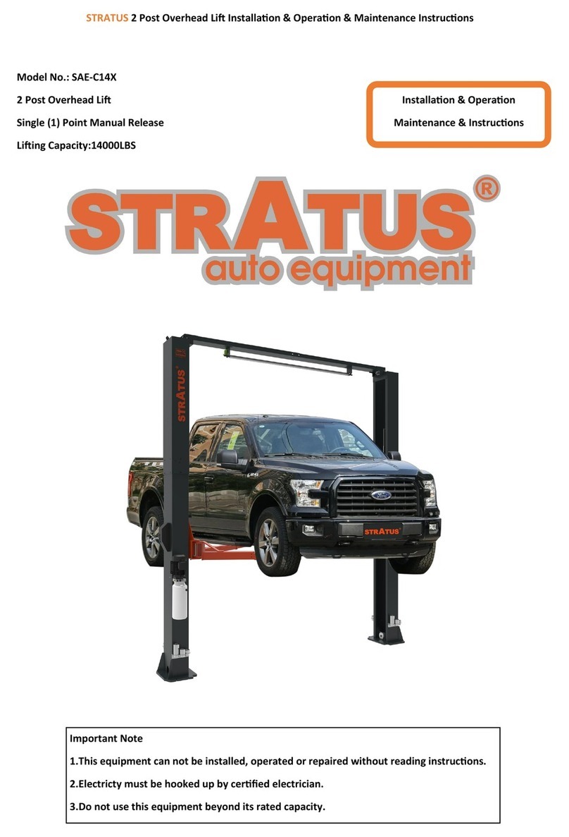
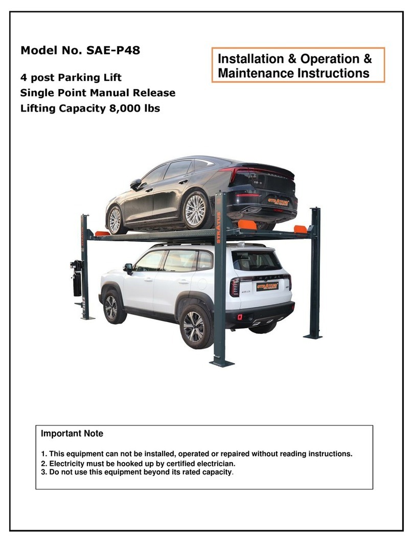
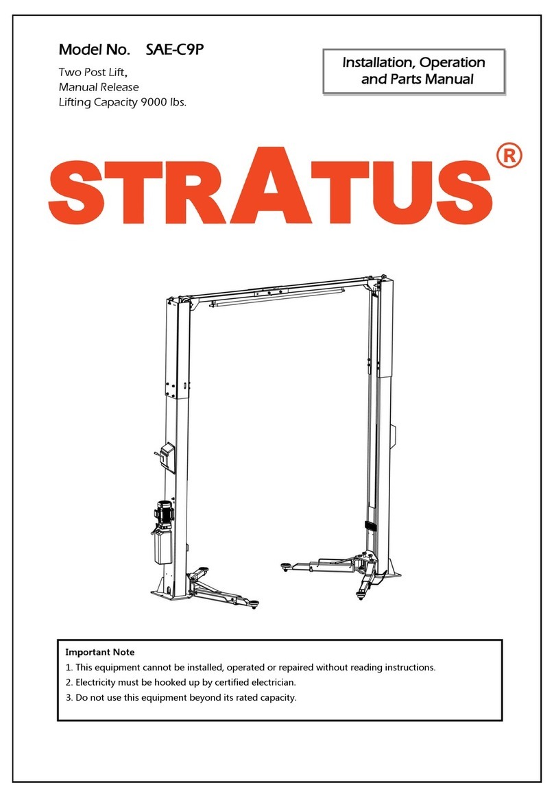
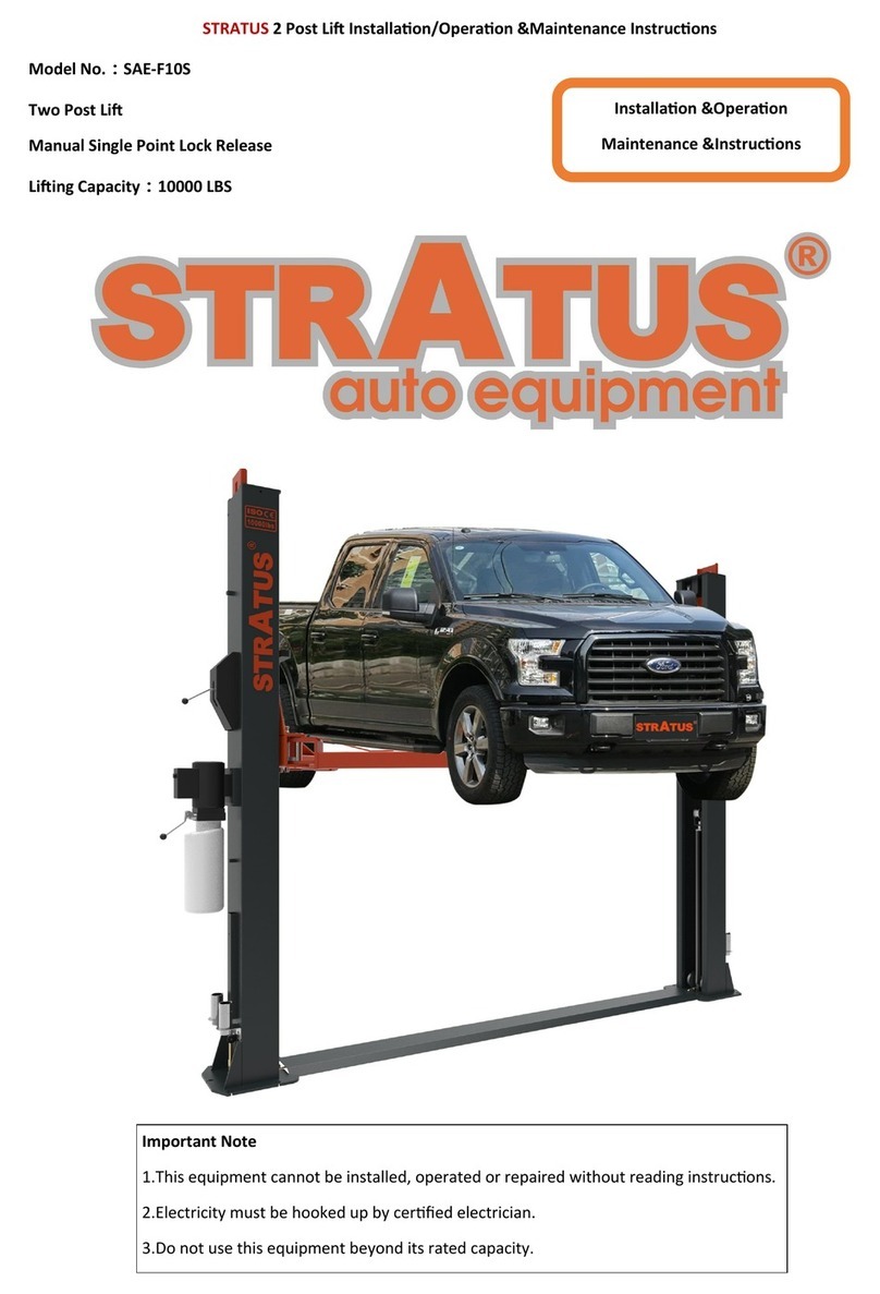
Stratus SAE-C12X Guide

Installaon & Operaon
Maintenance & Instrucons
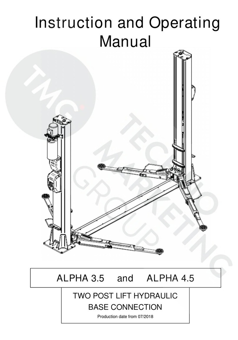
STRATUS 2 Post Overhead Li Installaon & Operaon & Maintenance Instrucons
Model No.: SAE-C12X
2 Post Overhead Li
Single (1) Point Manual Release
Liing Capacity:12000LBS
Important Note
1.This equipment can not be installed, operated or repaired without reading instrucons.
2.Electricty must be hooked up by cered electrician.
3.Do not use this equipment beyond its rated capacity.

2
CONTENTS
1-Equipment descripon
…………………………………………………………………………………………………
3
1.1-Descripon ……………………………………………………………………………………………………………3
1.2-Technical specicaons………………………………………………………………………………………………3
1.3-Installaon requirement………………………………………………………………………………………………5
2-Specicaons of concrete………………………………………………………………………………………………6
3-Installaon steps…………………………………………………………………………………………………………7
4-Operaon and use………………………………………………………………………………………………………18
4.1-Operaon ……………………………………………………………………………………………………………18
4.2-Raising Liing…………………………………………………………………………………………………………18
4.3-Stopping ………………………………………………………………………………………………………………18
4.4-Lowering ………………………………………………………………………………………………………………18
5-Safety ……………………………………………………………………………………………………………………18
5.1-Important Reminder…………………………………………………………………………………………………18
5.2-Vehicle Posion………………………………………………………………………………………………………19
5.3-Risk of Vehicle falling o from the li…………………………………………………………………………19
6-Maintenance ……………………………………………………………………………………………………………19
6.1-Every Month …………………………………………………………………………………………………………19
6.2-Every 3Month ………………………………………………………………………………………………………19
6.3-Every 6Month ………………………………………………………………………………………………………20
6.4-Every 12 Moth ………………………………………………………………………………………………………20
7-Troubleshoong guide …………………………………………………………………………………………………20
8-Structure and Parts List…………………………………………………………………………………………………21
8.1-Main column assembly……………………………………………………………………………………………21
8.2-Sun-column assembly………………………………………………………………………………………………21
8.3-Block assembly………………………………………………………………………………………………………22
8.4-Cross arm assembly…………………………………………………………………………………………………22
8.5-Cylinder assembly……………………………………………………………………………………………………23
8.6-Three-secon arm assembly………………………………………………………………………………………23
8.7-Main column safety lock assembly………………………………………………………………………………24
8.8-Secondary column safety lock assembly…………………………………………………………………………25

3
1.-Equipment Descripon
1.1-Descripon
This 2 Post Overhead Li is an advanced car maintenance equipment, mainly used for automove repair and
maintenance.
1.2-Technical Specicaons
Model SAE-C12X
Liing capacity 12000lbs;5500KG
Overall Hight 173 3/8″;4403mm
Overall Width 155 1/8″;3940mm
Liing height 74 13/16";1900mm
Min. height 4 5/8";118mm
Column inside 129 15/16";3300mm
Drive through 115 11/16";2939mm
Liing me About 60 sec.
Lowering Time About 40 sec.
Column thickness of steel 6.0mm
Carriage thickness of steel 6.0mm
Arms thickness of steel 7.75mm
Arm range 35 1/16"-70 7/8";890-1800mm;
Diameter of cable Φ9mm
Voltage 220V
Power 3.0Kw/4Hp
Frequency 60Hz
Phase 1Ph
Breaker 30A
Hydraulic oil 3-5 Gallons AW46/AW32
Shipping Size 118"×44″×28";2997×1118×712mm
Equipment weight 2360lbs/1071KG

4
Installaon( See Fig 1 )
FIG 1
Features (See Fig 2)
FIG 2

5
1.3-Installaon requirement
Tools required
Name
Picture
Rotary hammer drill(Φ19)
carpenter's chalk
Hammer
Screw Sets
Level bar
Tap measure
English spanner(12")
Pliers
Ratchet spanner with socket(28#)
Socket head wrench(3#,5#,8#)
Lock wrench
Wrench set(10#,13#,14#,15#,17#,19,24#,27#,30#)

6
2-Specicaons of concrete ( See Fig 3 )
Specicaons of concrete must be adhered to the specicaon as following. Failure to do so may result in li and/or
vehicle falling.
◇Concrete must be thickness 200mm minimum and without reinforcing steel bars, and must be completely dry
before li installaon.
◇Concrete must be in good condion and must be of test strength 3500psi(245kg/cm²)minimum.
◇Floor must be level with no cracks or holes.
Steps of installaon
◇Locaon of installaon
Check and insure the installaon locaon( concrete, layout, space size etc.) is suitable for li installaon.
◇Use a carpenter's chalk line to establish installaon layout of baseplate( See Fig4).
FIG 3
FIG 4

7
3-Installaon steps
Step 1:Check the pats before assembly
Packaged li and hydraulic power unit( See Fig 5 )
Step 2:Move aside the parts and check the parts according to the shipment parts list (See Fig 6).
FIG 5
FIG 6

8
Step 3: Spare parts in the accessories box.
Serial
number
Name Photo Parameter Quanty
1Arm sha Φ40×250L 4
2Arm sha xing screw
Countersunk Hexagon Screw M10×15L 4
3Arm boom pad Φ70mm 4
4Increased set Φ60×100L 4
5Heightening bracket 2
6Heightening sleeve bracket xing
screw
Hexagon socket screws M8×10L 2
7An-collision tape 2
8An-collision rubber strip xing screws
Hexagon socket screws M8×30 4
9Power unit frame 1
10 Power unit frame xing screws
Hexagon socket screws M10×16L Each 2
11 Power unit xing screws
Hexagon Screw M8×25L Each 4
12 Manual unlocking lever M10 Each 1
13 Safety lock release cable 1
14 Wire rope U-shaped chuck M3 2
15 Expansion screw
M20×160L 14

9
Serial
number
Name Photo Parameter Quanty
16 Plasc gasket 15
17 Plasc cable e 30
18 Main column upper limit switch 1
19 Main column upper limit switch xing screw Phillips round head screws M5×10L 2
20 Upper limit plate and limit switch M4×10 and M4×25 1
21 Upper limit board 1
22 Upper limit plate xing screw Hexagon Screw M10×20L Each 4
23 Two cross arm connecng screws Hexagon Screw M8×20L Each 6
24 Two-secon cross arm end xing screws Hexagon Screw M10×25L Each 8
25 Heightening secon and column connecng
screw
Hexagon socket screws M10×12L Each 16
26 Wire rope support frame at the upper end of
the heightening secon
2
27 Fixing screws for the upper wire rope sup-
port frame of the heightening secon
Hexagon socket screws M5×10L 4
28 Plasc buckle cover xing screw Phillips round head screws M6×8L 8
29 Increased fuel-saving pipe pressure pocket 6
30 Increased the fuel-saving pipe pressure pock-
et xing screw
Hexagon socket screws M6×10L Each 12
31 Block rubber cover 2
32 Locking and unlocking rope seat assembly
accessories
2
33 User’s manual 1

10
Step 4: Install anchor bolts
Posion the columns on the installaon layout of baseplate. Install the anchor bolts. Check the columns plumbness
with level bar, and adjusng with the shims if the columns are not vercal. Do not ghten the anchor bolts (See Fig 7).
Note: Anchor bolts driven into the ground at least 150mm.(See Fig 8)
FIG 8
FIG 7

11
STEP 5:Column and height-increasing joint connecon installaon. (See Fig 9)
Step 6:Cross arm installaon (See Fig 10) FIG 9
FIG 10
NO. Name Qty.
1Main column heightening secon 1
2Main column welding 1
3Socket head cap screws M10×12 10
4Flat pad 10
No. Name Qty.
1Main cross arm assembly 1
2Assembly of auxiliary crossarm 1
3Hex bolts M10×20 4
4Flat pad Φ10 4
5Spring cushion Φ10 4
6Hex nuts M10 4
7Hex bolts M8×20 6
8Flat pad Φ8 6
9Spring cushion Φ8 6
10 Hex nuts M8 6

12
Step 7:Cross arm and height-increasing secon connecon installaon (See Fig 11)
FIG 11
Step 8: Unlock wire rope installaon (See Fig12)
No. Name Qty.
1Main column heightening secon 1
2Main cross arm assembly 1
3Hex bolts M10×25 4
4Flat pad Φ10 4
5Spring cushion Φ10 4
6Hex nuts 4
No. Name Qty.
1Main column heightening secon 1
2Secondary column heightening secon 1
3Unlock the thin wire rope 1
4Unlock wire bracket 1 1
5Unlock wire bracket 2 1
6Tubing pressure pocket 6

13
FIG 12
No. Name Qty.
1Main column assembly 1
2Unlock the thin wire rope 1
3Unlock the sheave seat 1
4Safety lock cover (Opening) 1
5Unlock lever 1
6Phillips round head screw M6×10 4
No. Name Qty.
1Sub-column assembly 1
2Unlock the thin wire rope 1
3Unlock the sheave seat 1
4Safety lock cover 1
5Phillips round head screws M6×10 4

14
Step 9:Equalized cable installaon (See Fig13)
Connect steel cables
1. Route and x according to the following diagram of steel cable connecon.
2. Raise both carriages to the rst locking point.
3. Make sure that the mechanical safety locks in each post are fully engaged before aempng to route cables.
4. Aer the cable being xed, adjust and make the cable at both sides be with the same ghtness which could be
judged by the sound emied during liing process. Make judge and adjustment aer trial running.
5. Grease aer being xed. (It is a must.)
Step 10: Hydraulic tubing connecon installaon (See Fig 14).
FIG 13
FIG 14
No. Name Qty.
1Power unit 1
2Hydraulic cylinder 2
3Hose 1 1
4Tee connector 1
5Hose 2 1
6Hose 3 1

Step 11:Limit switch connecon installaon (See Fig15)
Funconal descripon of each part of the power unit
Fig 15
**Important Informaon**
Pressure Valve: Clockwise adjustment increases pressure to make the power
unit to have more power, counterclockwise adjustment decreases pressure to
make the power unit to have less power.
Hydraulic Oil ow valve: Clockwise adjustment to speed up, counterclockwise
adjustment to slow down.

16
Fill with hydraulic oil.
CLEAN AND FRESH OIL ONLY
DON’T FILL THE TANK COMPLETELY FULL.
Li must be fully lowered before changing or adding hydraulic oil
Pour 13 liters HM32 an-abrasion hydraulic oil into the oil tank. The level of oil shall reach the ppets volume mark
of the tank.
Add more oil aer running the li for several cycles unl the li can rise to the maximum liing height.
Note:As running speed of the li is mainly decided by the viscosity of the hydraulic oil, we suggest using NO.46
hydraulic oil when average temperature of the locaon is above 18 degree Celsius and using NO.32 hydraulic oil
when temperature is below 18 degree
Celsius. Change the oil 6 month aer inial use and change once per year thereaer.
Step 12: Power unit installaon (See Fig 16)
Fig 16
No. Name Qty.
1Main column assembly 1
2Power unit 1
3Power unit backpack 1
4Flat pad Φ10 2
5Spring cushion Φ10 2
6Socket head cap screws M10×16 2
7Hex nuts M8 4
8Flat pad Φ8 4
9Spring cushion Φ8 4
10 Hex bolts M8×25 4
11 Heightening bracket 1
12 Socket head cap screws M8×10 2
13 Increase the set 1 1

17
Step14: Trial running. (See Fig 18)
Get familiar with li controls by running the li through a few cycles before loading vehicle on li. This step is of par-
cular importance for it can check if the oil hose is well connected. The connecon is qualied when there is no ab-
normal sound or leakage aer having been tested for 5-6 mes.
Bleeding the hydraulic system
Unscrew but don't remove the nut on top of the oil cylinder and slightly press the UP buon unl oil gets out. Screw
the nut ght thereaer. Aer bleeding, oil level in power unit reservoir may be down. Raise and lower li several
cycles. Add more oil if necessary to raise li to full height. It is only necessary to add oil to raise li to full height.
Step13: Install liing arms. (See Fig 17)
Connect the liing arm and the carriage. The arm pin shas must be greased at the installaon Ensure the arm lock
can engage and release eecvely. .
Aenon: Install Liing arms and x feet protecon bars ONLY aer the complete assembly has been erected and
anchored.
FIG 17
FIG 18
No. Name Qty.
1Arm sha 2
2Socket head cap screws M10×16 2
3Arm boom pad 2
4Welding of support arm 2
5An-collision tape 1
6Socket head cap screws M8×30 2

18
4-Operaon and Use
4.1-Operaon
Place the liing arm at the support point specied by the vehicle and adjust the rubber tray to the same height.
Check the posion of the rubber tray under the vehicle chassis before each single raising or when vehicle is lowered
to the ground and need to raise again.
4.2-Raising/ Liing
Press the power switch unl the vehicle reaches desired height. When the vehicle is raised, the safety lock automa-
cally engaged.
During raising/liing, whether the arm lock has been locked, it can be visually checked when it is raised to a certain
height (stop and check).
*Danger*: Unlocked arms can cause vehicle fall o from the li.
4.3-Stopping
Aer raising to desired height, press the lower lever and the li will automacally lower to a safe posion, the safety
lock will be engaged and the li will be locked.
4.4-Lowering
The safety lock must be released before lowering.
1. Press the power switch to raise the car by approximately 30mm/1.2".
2. Pull the safety lock release cables on both sides to unlock.
3. Press the lower lever to start lowering process, the arm lock will be automacally released and allow the arm ro-
tang when the vehicle is completely lowered to the ground.
5-Safety
Please read this manual carefully as it contains important safety informaon that the operators need to know.
*WARNING*: The design and construcon of this li is only suitable for liing whole vehicle. All other uses are unau-
thorized, this li CAN NOT be used to : wash vehicles, build liing plaorms, liing personnel, use as cargo lis and
use as liing paral of the vehicles.
5.1-Important Reminder: Personal and Equipment Safety
1. During vehicle liing process, operators should be at a safe posion/area.
2. Turn o the vehicle engine and manual brake on.
3. Load vehicle correctly (Fig 19).
4. The vehicle CAN NOT exceed the rated liing capacity and required size.
Fig 19

19
5.2-Vehicle Posion
Once the vehicle is raised, vehicle CAN NOT be moved backwards or forwards as it may cause falling.
*WARING*: Do not aempt to move the vehicle while it is parked on the li.
5.3-Risk of Vehicle falling o from the li
Note that when posioning the vehicle on the li, incorrect center of gravity of the vehicle can cause the vehicle
falling o from the li (Fig 20).
Important Note: Make sure that the front and rear of the vehicle need to be balanced and the cables on both sides
also need to be balanced. Do not board/step on the vehicle or the li when the li is raised.
Below acons may cause the vehicle fall o from the li .(Fig 21)
Fig 21DO TOT do
FIG 20
6-Maintenance
6.1-Every Month
Hydraulic System
1. Check hydraulic oil level, ll hydraulic oil if necessary.
2. Check the pump, hose and cylinder and see if there is hydraulic oil leaking.
6.2-Every 3 Month
Safety Maintenance
1. Check the condion of the safety lock and the wear of the stop block.
2. Check the anchor bolts, ghten nuts if necessary.
3. Check if any nuts are loose, ghten nuts if necessary.
4. Check if the arm locking system is working properly.
5. Lubricate/grease all moving parts.
6. Check if the arm locking system is working properly.
7. Check if the 2 carriage on both sides are at the same level.

20
7. Troubleshoong Guide
Troubleshoong Guide
Malfuncon Possible reason Soluon
The motor does not
work
Check the air switch. Turn o or replace the air switch.
Check if the voltage is correct. User correct power supply.
The motor burned. Replace the motor.
Start switch burned. Replace the start switch.
Top limiter switch burned. Replace the top limiter switch.
AC contactor burned. Replace the AC contactor.
The motor works
but can’t li
Pressure valve pressure is too small. Clockwise adjust the pressure valve( ne adjust-
ment).
Pump staon takes in air.
Unscrew check valve on the power unit, and then
start the motor unl hydraulic oil ows out from the
check valve.
Hydraulic oil sucon hose is detached or broken. Install/replace the sucon hose.
Insucient hydraulic oil. Fill more hydraulic oil.
Does not lowering
Safety lock engaged. Slightly raise the device and then pull the safety lock
release cable.
Other object inside the columns stops the carriage. Check and remove the objects.
The ow valve needs to be adjusted. Counterclockwise adjust the ow valve (ne adjust-
ment).
Self-Lowering
Dump valve failure. Replace the dump valve.
Hydraulic oil leaks. Check and repair.
The valve body of the power unit has holes. Replace the valve body.
Raise without load,
but doesn’t raise
with load
The voltage is too low. Install the voltage stabilizer.
Objects in the dump valve. Remove objects from the dump valve.
The pressure valve pressure is too small. Increase pressure properly( ne adjust the pressure
valve).
Overload. This operaon is prohibited.
Liing is not leveled The cables are not balanced. Balance cables by adjusng the cable’s length.
Aer raising to the highest point, the motor is sll working
and the top limiter switch is disabled. Replace the top limiter switch.
Loud motor noise Hydraulic oil polluon. Replace the hydraulic oil.
Overload. This operaon is prohibited.
6.3-Every 6 Month
Hydraulic Pump
1. Check the condion and aging of the hydraulic uid. Unqualied hydraulic uid is the main reason to cause valve
failure and reduces the life of the gear pump.
2. Check the noise variaon of the motor and gear pump while normal operang.
6.4-Every 12 Month
1. Visually inspect all structural and mechanical parts to make sure there is no abnormalies have occurred.
2. Check and see if there is anything wrong with the motor, wiring ,top limiter switch and circuit breaker.
Table of contents
Other Stratus Lifting System manuals
Stratus
Stratus MS9000XT User manual
Stratus
Stratus SAE-F12X Guide
Stratus
Stratus SAE-C10C Guide

Stratus
Stratus SAE-P410 User manual
Stratus
Stratus SAE-F10P Guide
Stratus
Stratus SAE-F14X Guide

Stratus
Stratus SAE-C12XE Guide
Stratus
Stratus SAE-S66M User manual
Stratus
Stratus SAE-P166M Guide
Stratus
Stratus SAE-UT9000 Guide

