WITTUR WCS60 User manual

Car Frame WCS60
Suspension 2:1 / 4:1
Operating instructions
Car Frame WCS60 Suspension 2:1 / 4:1
Blatt/
sheet
D389MGB.000
Datum/
date
11.02.2002
Stand/
version
C-23.07.2015
Geprüft/
approved
WAT/FLE
D389MGB 07.2015
No part of this publication may be reproduced or
translated, even in part, without prior written
permission from WITTUR Austria GmbH.
Änderungen vorbehalten!
We reserve the right to make alterations with respect
to the specifications and figures in this manual.
Subject to change without notice!
WITTUR Austria GmbH
Sowitschstrasse 1 • A-3270 Scheibbs, Austria
Tel. +43 (0) 7482/42542-0 •Fax +43 (0) 7482/42542-232
http://www.wittur.com •E-Mail: info.at@wittur.com
*D389MGB$111*
fa=råáèìÉ=PM.3.002352.EN

Contents Page
1 General information prior to installation
1.1 Description and functions . . . . . . . . . . . . . . . . . . . . . . . . . . . . . . . . . . . . . . . . . . .D389MGB.002
1.2 Liability and guarantee . . . . . . . . . . . . . . . . . . . . . . . . . . . . . . . . . . . . . . . . . . . . . .D389MGB.002
1.3 Safety precautions . . . . . . . . . . . . . . . . . . . . . . . . . . . . . . . . . . . . . . . . . . . . . . . . . .D389MGB.003
1.4 Preparation . . . . . . . . . . . . . . . . . . . . . . . . . . . . . . . . . . . . . . . . . . . . . . . . . . . . . . . .D389MGB.003
1.5 Safety gear name plate . . . . . . . . . . . . . . . . . . . . . . . . . . . . . . . . . . . . . . . . . . . . . .D389MGB.004
1.6 Content of supply . . . . . . . . . . . . . . . . . . . . . . . . . . . . . . . . . . . . . . . . . . . . . . . . . .D389MGB.005
2 Installation
2.1 Placing the bottom cross beam between the rails . . . . . . . . . . . . . . . . . . . . . . .D389MGB.007
2.2 Securing the uprights to lower cross beam . . . . . . . . . . . . . . . . . . . . . . . . . . . . .D389MGB.008
2.3 Installing Crosshead beam . . . . . . . . . . . . . . . . . . . . . . . . . . . . . . . . . . . . . . . . . . .D389MGB.009
2.4 Installing isolated platform supports . . . . . . . . . . . . . . . . . . . . . . . . . . . . . . . . . .D389MGB.010
2.5 Installing “non-isolated” platform supports . . . . . . . . . . . . . . . . . . . . . . . . . . . . .D389MGB.010
2.6 Installing the diagonal rods . . . . . . . . . . . . . . . . . . . . . . . . . . . . . . . . . . . . . . . . . .D389MGB.011
2.7 Travelling cable hanger and compensation chain fixings . . . . . . . . . . . . . . . . . .D389MGB.012
2.8 Car installation (isolated platform support) . . . . . . . . . . . . . . . . . . . . . . . . . . . . .D389MGB.013
2.9 Car installation (non-isolated platform support) . . . . . . . . . . . . . . . . . . . . . . . . .D389MGB.014
2.10 Finalizing Car installation . . . . . . . . . . . . . . . . . . . . . . . . . . . . . . . . . . . . . . . . . . . .D389MGB.015
2.11 Tightening of diagonal rods . . . . . . . . . . . . . . . . . . . . . . . . . . . . . . . . . . . . . . . . . .D389MGB.015
2.12 Car fixing bolts (isolated platform support) . . . . . . . . . . . . . . . . . . . . . . . . . . . . .D389MGB.015
2.13 Roping of the car frame . . . . . . . . . . . . . . . . . . . . . . . . . . . . . . . . . . . . . . . . . . . . .D389MGB.016
2.14 Overspeed governor rope fixing . . . . . . . . . . . . . . . . . . . . . . . . . . . . . . . . . . . . . . .D389MGB.017
2.15 Adjustment of safety gear . . . . . . . . . . . . . . . . . . . . . . . . . . . . . . . . . . . . . . . . . . .D389MGB.018
2.16 Load weighing device WLWD-M . . . . . . . . . . . . . . . . . . . . . . . . . . . . . . . . . . . . . .D389MGB.019
3 Function testing . . . . . . . . . . . . . . . . . . . . . . . . . . . . . . . . . . . . . . . . . . . . . . . . . . . . . .D389MGB.020
4 Maintenance, inspection and repair
4.1 Maintenance and inspection . . . . . . . . . . . . . . . . . . . . . . . . . . . . . . . . . . . . . . . . .D389MGB.021
4.2 Carrying out repairs . . . . . . . . . . . . . . . . . . . . . . . . . . . . . . . . . . . . . . . . . . . . . . . . .D389MGB.022
4.3 Spare parts list . . . . . . . . . . . . . . . . . . . . . . . . . . . . . . . . . . . . . . . . . . . . . . . . . . . . .D389MGB.023
Car Frame WCS60
Suspension 2:1 / 4:1
Operating instructions
Blatt/
sheet
D389MGB.001
Datum/
date
11.02.2002
Stand/
version
11.02.2002
Geprüft/
approved
WAT/FLE
Änderungen vorbehalten! Subject to change without notice!

1.1 Description and functions
The car frame WCS60 is a car frame used for pas-
senger-goods and freight elevators with nominal
load up to 6000kg.
The car frame operating range is defined as fol-
lows:
WCS60:
• All up load ≤ 17000 kg (Q ≤ 6000 kg)
• Car depth ≤ 6500 mm
• Car width ≤6290 mm
• Rated speed ≤2.0 m/s
General:
• Safety gear: Roller type SG
Progressive type SG
• Sliding guide shoe (SLG4, SLG4A)
• Suspension: 2:1 and 4:1 with 2 pulleys
above car
Further options:
• Load weighing system
• Platform support beams
• Compensation chain hanger
• Travelling cable hanger
The built-in safety devices are set, synchronized
and lead sealed ex-works, according to the order.
For reasons of safety, it is forbidden to readjust
these settings once they have been made.
1.2 Liability and guarantee
This instruction handbook is written for people
who are familiar with lift servicing and installa-
tion. Sufficient knowledge of lifts is essential.
WITTUR accept no responsibility for damage
caused by improper handling, or for damage
caused as a result of actions other than those stat-
ed in these operating instructions.
The WITTUR guarantee may be voided if parts
other than those described in these instructions
are installed.
Unless stated otherwise, the following are not per-
missible due to technical safety reasons:
• The use of safety gear devices or brake com-
ponents other than those installed
• Carrying out modifications, of any kind, on
brake components
• Destroying of seals
• Frame modification
• Modification of the actuating mechanism
• Readjustment of settings have been made ex-
works
• Carrying out faulty or improper maintenance,
maintenance or inspection checks
• using unsuitable accessories, spare parts or
operating material which has neither been re-
leased by the WITTUR Company nor consists of
original WITTUR spare parts
Car Frame WCS60
Suspension 2:1 / 4:1
Operating instructions
Blatt/
sheet
D389MGB.002
Datum/
date
11.02.2002
Stand/
version
11.02.2002
Geprüft/
approved
WAT/FLE
Änderungen vorbehalten! Subject to change without notice!
1 General information prior to installation

1.3 Safety precautions
WITTUR machine installation or repair engineers
are chiefly responsible for the safe operation of
machinery.
It is essential to comply with and keep abreast of
all safety rules and legal obligations in order to
avoid personal / product damage during installa-
tion, maintenance and repair work.
Important safety advice and danger warnings are
emphasized with the following symbols:
General danger warning
High danger risk warning (i.e. crushing
edge, cutting edge etc.).
Risk of damage to machinery parts (i.e. due
to incorrect installation, or such like).
Important information sign
These operating instructions belong with the
whole installation and must be kept in a safe place
at all times (i.e. machine room).
The proper assembly and installation of WITTUR
car frames requires correspondingly well trained
fitting engineers. The responsibility of training lies
with the company appointed to carry out the
work.
Before starting installation work:
Only properly trained personnel may carry
out work, or be allowed access to the
installation site.
- Attach safety devices to guard against falling
(platform or harnesses)
- Cover any floor openings
- Secure installation tools or objects against
accidental falling
- Lift shaft openings should be cordoned off
and suitable warning signs should be erected
when working in shaft openings
- Work involving electrical equipment should
only be carried out by an electrical engineer or
qualified personnel.
1.4 Preparation
Before beginning installation work it is in your
own interest to ascertain the constructional and
spatial conditions. Where (workshop or on site)
and when which installation operations can or
must be carried out. It is recommended therefore,
taking into account all the given circumstances, to
plan the various operational sequences in advance,
rather than carrying them out prematurely and in
an unconsidered manner.
On receipt of the delivery, the goods or compo-
nents should be checked for correctness and com-
pleteness with the order sheet
The details on the name plates should be com-
pared with the order sheet and also check:
- that the factory and order number correspond
- the rail head width and model
- the total load (G)
- the tripping speed
- the rope pulley diameter, the number of rope
grooves and rope groove diameter are suited
to the ropes
Car Frame WCS60
Suspension 2:1 / 4:1
Operating instructions
Änderungen vorbehalten! Subject to change without notice!
Blatt/
sheet
D389MGB.003
Datum/
date
11.02.2002
Stand/
version
11.02.2002
Geprüft/
approved
WAT/FLE

1.5 Safety gear name plate
The safety gear device identification indicators are
located near the safety block. These consist of a
name plate and a identification sticker.
Car Frame WCS60
Suspension 2:1 / 4:1
Operating instructions
Änderungen vorbehalten! Subject to change without notice!
Blatt/
sheet
D389MGB.004
Datum/
date
11.02.2002
Stand/
version
11.02.2002
Geprüft/
approved
WAT/FLE
Serial number
Tripping speed
vmax = (m/s,fpm)
Type term
Order number
(refer to delivery
or order sheet)
Mass to be gripped
Fmax = (kg,lb)
Type test designation
and CE-label
Date of manufacture

1.6 Content of supply
After delivery, check the lift car frame for damage
and for full delivery of parts. The content of sup-
ply covers:
- Car frame operating instructions manual
- Safety gear operating instructions manual
- Guide shoe operating instructions manual
- Load weighing dev. operating instr. manual
- Crosshead beam incl. rope pulleys
(pre-assembled)
- Bottom Cross beam incl. safety gear and syn-
chronization
(pre-assembled and pre-adjusted)
- Ringbeams
- Diagonals and fixing brackets
Car Frame WCS60
Suspension 2:1 / 4:1
Operating instructions
Blatt/
sheet
D389MGB.005
Datum/
date
11.02.2002
Stand/
version
11.02.2002
Geprüft/
approved
WAT/FLE
Änderungen vorbehalten! Subject to change without notice!
Car Frame WCS60
Suspension 2:1 / 4:1
Operating instructions
Car Frame WCS60 Suspension 2:1 / 4:1
Blatt/
sheet
D389MGB.000
Datum/
date
11.02.2002
Stand/
version
11.02.2002
Geprüft/
approved
WAT/FLE
D389MGB 02.2002
THELMC LIFTCOMPONENTS MANUFACTURING AND COMMERCE COMPANY
No part of this publication may be reproduced or
translated,even in part, without prior written permis-
sion fromWITTUR GmbH.
Änderungenvorbehalten!
Wereserve the right to make alterations with respect
to the specifications and figuresin this manual.
Subjectto change without notice!
WITTUR GmbH
Sowitschstrasse 1 • A-3270 Scheibbs, Austria
Tel.+43 (0) 7482/42542-0 •Fax +43 (0) 7482/42542-32
http://www.wittur.at•E-Mail: info@wittur.at
Progr. type safety gear
SGB01, SGB02, SGB03, SGB05
Blatt/
sheet
D7A4MGB.000
Datum/
date
24.08.2001
Stand/
version
24.08.2001
Geprüft/
approved
WAT/FLE
D7A4MGB 02.2002
THELMC LIFTCOMPONENTS MANUFACTURING AND COMMERCE COMPANY
Nachdruck, Übersetzung und Vervielfältigung in
jeglicher Form - auch auszugsweise - bedürfen der
schriftlichen Genehmigung der WITTURAG.
Änderungenvorbehalten!
Änderungen gegenüber den in dieser Betriebsanlei-
tung aufgeführten Angaben und Abbildungen behal-
ten wir uns vor.
Subjectto change without notice!
WITTUR GmbH
Sowitschstrasse 1 • A-3270 Scheibbs, Austria
Tel.+43 (0) 7482/42542-0 • Fax +43 (0) 7482/42542-32
http://www.wittur.at•E-Mail: info@wittur.at
Progr. type safety gear SGB01, SGB02,
SGB03, SGB05
Operating instructions
Sliding guide shoes
Operating instructions
Sliding guide shoes
for car frame and counterweight
Blatt/
sheet
D622MGB.000
Datum/
date
24.01.2002
Stand/
version
24.01.2002
Geprüft/
approved
WAT/FLE
D622MGB 01.2002
THELMC LIFTCOMPONENTS MANUFACTURING AND COMMERCE COMPANY
WITTUR GmbH
Sowitschstrasse 1 • A-3270 Scheibbs, Austria
Tel.+43 (0) 7482/42542-0 •Fax +43 (0) 7482/42542-32
http://www.wittur.at•E-Mail: info@wittur.at
No part of this publication may be reproduced or
translated,even in part, without prior written permis-
sion fromWITTUR GmbH.
Änderungenvorbehalten!
Wereserve the right to make alterations with respect
to the specifications and figuresin this manual.
Subjectto change without notice!
Sliding guide shoe
Guide rail lubricator
Electronic Load Weighing Device
WLWD-M
Operating instructions
Electronic Load Weighing Device
Blatt/sheet D961MGB.000
Datum/date 31.01.2002
Stand/version 31.01.2002
Geprüft/approved WAT/FLE
D961MGB 01.2002
THELMC LIFTCOMPONENTS MANUFACTURING AND COMMERCE COMPANY
No part of this publication may be reproduced or
translated,even in part, without prior written permis-
sion fromWITTUR GmbH.
Änderungenvorbehalten!
WITTUR GmbH
Sowitschstraße1, • A-3270 Scheibbs, Austria
Tel.+43 (0) 7482/42542-0 •Fax +43 (0) 7483/42542-32
http://www.wittur.at•E-Mail: info@wittur.at
Wereserve the right to make alterations with respect
to the specifications and figuresin this manual.
Subjectto change without notice!
Progressive type
safety gear
Instantaneous
type safety gear
or

- Uprights
- Platform supports incl. lower car fixing
material (optional)
Accessories:
- Upper car fixing (incl. isolation buffer)
- Guide shoes
- Screw packages
Optional parts:
- Load weighing sensors
(incl. amplifier box)
- Compensation chain fixing
- Travelling cable hanger
Car Frame WCS60
Suspension 2:1 / 4:1
Operating instructions
Blatt/
sheet
D389MGB.006
Datum/
date
11.02.2002
Stand/
version
11.02.2002
Geprüft/
approved
WAT/FLE
Änderungen vorbehalten! Subject to change without notice!

Car frame installation can either be carried
out at the bottom of the lift shaft or on a
stable installation platform in the lift
shaft. Also guide clamps could be used
which can take the total load of frame and
car!
The guide rails should have been already
properly set. The distance between the
guide rails should be checked before
installing the car frame.
2.1 Placing the bottom cross beam
between the rails
The bottom cross beam is delivered pre-assembled.
It contains the safety gear, the synchronization
and the buffer plates. The safety gear is bolted and
synchronized.
(1) If WCS60 is delivered with duplex (double)
safety gear, remove one guide rail. Mark the
location of the guide before removing.
(1a)If WCS60 is delivered with progressive type
safety gear, set the cross beam at an angle (see
Fig.).
(2) Clip one safety gear head onto the rail
(3) Turn Cross beam back into the horizontal posi-
tion, pushing the second safety gear device
onto the rail.
(4) Re-install the guide rail
(5) Adjust the cross beam in the middle of the
guide rails (safety gear gripping wedge must
overlap guide rail blade)
Check that the beam is horizontal in the
lateral direction.
(6) Fix the guide shoe to the safety gear housing
(for setting refer to operating instruction
manuals of guide shoes)
Take care of tightening torque
Screw M20: 385Nm
Note the correct position of the bottom
cross beam in relationship to the governor
rope position (check layout drawing).
During installation the frame must be sup-
ported so that it does not rest on the
guides.
(6)
(5)
Car Frame WCS60
Suspension 2:1 / 4:1
Operating instructions
Änderungen vorbehalten! Subject to change without notice!
2 Installation
Blatt/
sheet
D389MGB.007
Datum/
date
11.02.2002
Stand/
version
11.02.2002
Geprüft/
approved
WAT/FLE
Screw ... M20x40 (12x)
(1a)
(1)
(2)
(2)(3)
(1,4)

(7) Lift OSG-lever by hand and
(8) ... secure it with a rope or wire around nearest
guide fixing
2.2 Securing the uprights to lower
cross beam
(1) Install the uprights to the bottom cross beam
Tighten the screw joints loosely only!
(2) Adjust the uprights in plumb and in centre to
the guide rails.
(3) Before tightening the screw joints, pack out
the spaces between upright and cross beam
with the shims if necessary.
Take care of tightening torque
Screw M16: 195Nm
Car Frame WCS60
Suspension 2:1 / 4:1
Operating instructions
Blatt/
sheet
D389MGB.008
Datum/
date
11.02.2002
Stand/
version
11.02.2002
Geprüft/
approved
WAT/FLE
Änderungen vorbehalten! Subject to change without notice!
(7-8)
Screw ... M16x50 (32x)
Nut ........ M16
Safety nut ... M16
Shim
(3)
(1-2)

2.3 Installing Crosshead beam
The crosshead beam is delivered pre-assembled. It
contains the beams, the rope suspension pulleys
and adapter plates for the guide shoes.
(1) Lift in the crosshead beam into the uprights
(2) Fit the beam to the uprights. If necessary add
shims between beam and upright.
Take care of tightening torque
Screw M16: 195Nm
Screw M20: 385Nm
(3) Fit the guide shoe to the adapter plate (for
setting refer to operating instruction manuals
of guide shoe)
Car Frame WCS60
Suspension 2:1 / 4:1
Operating instructions
Blatt/
sheet
D389MGB.009
Datum/
date
11.02.2002
Stand/
version
09.09.2003
Geprüft/
approved
WAT/FLE
Änderungen vorbehalten! Subject to change without notice!
(1)
Remove lock-pin!
Screw ... M16x40 (32x)
Nut ........ M16
Safety nut ... M16
Shim
(2)
(3)
Screw ... M20x80 (12x)

2.4 Installing isolated platform sup-
ports
If the WCS60 is delivered with isolated platform
support beams ...
(1) Fit the platform support to the lower cross
beam
Tighten the screw joints loosely only!
(2) Check that the support beams are
in horizontal position.
(3) Tighten then all screw joints
Take care of tightening torque
Screw M16: 195Nm
2.5 Installing “non-isolated” platform
supports
If the WCS60 is delivered without isolated plat-
form support beams ...
(1) Fit the platform support to the lower cross
beam (adjust according car platform needs)
Tighten the screw joints loosely only!
(2) Check that the support beams are in horizon-
tal position.
Tighten screw joints after car platform is
adjusted!
(1-3)
(1-2)
Car Frame WCS60
Suspension 2:1 / 4:1
Operating instructions
Blatt/
sheet
D389MGB.010
Datum/
date
11.02.2002
Stand/
version
11.02.2002
Geprüft/
approved
WAT/FLE
Änderungen vorbehalten! Subject to change without notice!
Screw ... M16x70 (12x)
Screw ... M12x50

2.6 Installing the diagonal rods
(1) Bolt the fixing brackets to the uprights
Use upper fixing holes in the upright
(lower group is used for upper car isola-
tion).
If car frame is delivered without isolated
platform support beams go on with car
platform installation section 2.9.
(2) Install the ring beams below the platform
support beams
(3) Install the diagonal rods
Take care of tightening torque
Screw M12: 80Nm
Do not tighten the 4 nuts at
the lower ends of the support
now (refer to section 2.11)!
(2)
(3)
(1)
Car Frame WCS60
Suspension 2:1 / 4:1
Operating instructions
Blatt/
sheet
D389MGB.011
Datum/
date
11.02.2002
Stand/
version
11.02.2002
Geprüft/
approved
WAT/FLE
Änderungen vorbehalten! Subject to change without notice!
Screw ... M12x80 (12x)
Screw ... M12x35 (16x)
Screw ... M30
Nut ... M36

2.7 ravelling cable hanger and com-
pensation chain fixings
Before installing the car, fix the cable
hanger and chain fixings to lower cross
beam (for position refer to layout draw-
ing).
Take care of tightening torque
Screw M12: 80Nm
Car Frame WCS60
Suspension 2:1 / 4:1
Operating instructions
Blatt/
sheet
D389MGB.012
Datum/
date
11.02.2002
Stand/
version
11.02.2002
Geprüft/
approved
WAT/FLE
Änderungen vorbehalten! Subject to change without notice!
ravelling cable hanger types:
Compensation chain
fixing types:
Screw package
611604G..
Screw package
611604G..
Take care of different fixing
methods for different compen-
sation chain types.
Chain type:
WF10, QL10 or
similar
Other Chain
types

2.8 Car installation (isolated platform
support)
(1) Lift the car floor (A) onto the fixing plates (B)
of the platform support beams. Adjust the
floor to its place.
The car floor must not touch the uprights.
(2) Fit the T-bolt (D) to the car floor channel (E)
and move them to the opening at the fixing
plates.
(3) Fasten the car floor against the fixing plates
so that the disk washer (F) becomes fully com-
pressed.
Make sure that the T-bolts are hanging
freely from the openings of the platform
supports!
(4) Adjust the car floor horizontally
Secure the car by means of wooden sup-
ports at the front and rear edges.
(5) Tighten the nut (G) by hand
(6) Install the car walls and the roof.
Car Frame WCS60
Suspension 2:1 / 4:1
Operating instructions
Blatt/
sheet
D389MGB.013
Datum/
date
11.02.2002
Stand/
version
11.02.2002
Geprüft/
approved
WAT/FLE
Änderungen vorbehalten! Subject to change without notice!
(1-6)
A
B
G
D
E
F

2.9 Car installation (non-isolated
platform support)
(1) Lift the car floor (A) onto the support plates
(C). Adjust the floor and the plates to its place.
The car floor must not touch the uprights.
(2) Adjust the car floor horizontally
(3) Fasten the car floor against the support plates
(fasten all the screw joints)
Do not tighten the 4 nuts at the lower
ends of the support now (refer to section
2.11)!
(4) Install the ring beams below the car floor.
Needed holes (D=18mm) must be drilled into
the ring beam!
(5) Install the diagonal rods
Take care of tightening torque
Screw M12: 80Nm
(6) Install the car walls and the roof.
Car Frame WCS60
Suspension 2:1 / 4:1
Operating instructions
Blatt/
sheet
D389MGB.014
Datum/
date
11.02.2002
Stand/
version
11.02.2002
Geprüft/
approved
WAT/FLE
Änderungen vorbehalten! Subject to change without notice!
AC
(1-3)
(4)
(5)
Nut ... M36

2.10 Finalizing Car installation
(1) Fix the upper car isolation to the car roof
channel (handtighten T-bolts)
(2) Fix the upper car isolation to the upright
Take care of tightening torque
Screw M12: 80Nm
(3) Tighten the T-bolts
Take care of tightening torque
Screw M10: 46Nm
Remove the wooden supports under the
car floor!
2.11 ightening of diagonal rods
(5) Tighten the nuts (A) of all diagonals by hand
against the bottom fixing
(6) Tighten then the nuts (A) half a turn more, and
lock the fixing with the nut (B)
2.12 Car fixing bolts (isolated platform
support)
(7) Adjust the nut (C) so that the square washer
(D) has a distance of approx. 3mm to the sup-
port beam profile edge
(8) Push the square washer (D) against the nut by
means of the rubber ring (E)
(9) Lock the fixing with the nut (F)
(1,3)
M12x35 (12x)
Car Frame WCS60
Suspension 2:1 / 4:1
Operating instructions
Blatt/
sheet
D389MGB.015
Datum/
date
11.02.2002
Stand/
version
11.02.2002
Geprüft/
approved
WAT/FLE
Änderungen vorbehalten! Subject to change without notice!
(2)
(5-6)
A
B
(7-9)
C
D
E
F
T-bolt M10

2.13 Roping of the car frame
(1) Check that the diverter pulley is exactly in the
middle between the cross head beam profiles.
If necessary, loosen the lower nuts (A) of the
isolations a little and adjust the diverter pulley
in lateral direction.
(2) Remove the rope guards (B)
(3) Pass the rope round the diverter pulleys
When used number of ropes is
less than the number of grooves
on the diverter pulley, the ropes are placed
according to the figure below.
(4) Re-fit and adjust the rope guards (B) and the
rope pulley cover plates (C)
Ensure 3mm gap between rope guard and
ropes.
The car must be in the topmost floor
when adjusting the cover plates.
(5) If WCS60 is delivered with pulley safety cover
(D), mount it together with fixing nuts of the
rope guards (B).
Car Frame WCS60
Suspension 2:1 / 4:1
Operating instructions
Blatt/
sheet
D389MGB.016
Datum/
date
11.02.2002
Stand/
version
11.02.2002
Geprüft/
approved
WAT/FLE
Änderungen vorbehalten! Subject to change without notice!
(2)
(4)
4:1 Suspension
A
B
C
D

2.14 Overspeed governor rope fixing
(1) Install the rope housing to the safety gear lift-
ing lever.
Tighten the screw only so much, that the
rope housing can move a little.
(2) Fit and install the overspeed governor rope to
its place in the housing
(3) Install the rope grips
The rope grip clamp link must be on the
side of the rope end!
Car Frame WCS60
Suspension 2:1 / 4:1
Operating instructions
Blatt/
sheet
D389MGB.017
Datum/
date
11.02.2002
Stand/
version
11.02.2002
Geprüft/
approved
WAT/FLE
Änderungen vorbehalten! Subject to change without notice!
Package 392772G..
Progressive type
Safety gear
Roller type
Safety gear
OSG rope
A =350
A =250
Rubber square
washer
Safety gear
lever
Rope grip
Rope housing
(1)
(2-3)
(2-3)

2.15 Adjustment of safety gear syn-
chronization
The safety gear device (safety gear, synchroniza-
tion, safety gear contact) is delivered pre-adjusted.
Therefore no additional assembling of the safety
gear device is needed.
(1) Operate the safety gear lever by hand and
check that both safety gears begin gripping at
the same time
... If not (with progressive type safety gear):
(2) Loosen the screw joint (A) a little
(3) Pull the safety gear wedges on both sides
down so that the fixing links (B) are against
the spring block (C).
(4) Tighten the screw joints again without
changing the location of the safety gear
wedges.
(5) Check the safety gear contact
function - adjust if necessary
The contact must break just
before safety gear gripping!
Safety switch (manual- or self reset type)
- use category: AC 15, A300, Ue/Ie240V (3A)
-thermal current: Ithe = 10A
- insulation voltage: Ui= 250V AC
- protection type: IP 43
- approved in accordance: VDE 0470
IEC/EN 60947-5-1
(6) Adjust the safety gear in accordance with the
operating instruction manual
Take care of required safety gear running
clearance (referring also to the type of
guide shoe used)
Car Frame WCS60
Suspension 2:1 / 4:1
Operating instructions
Blatt/
sheet
D389MGB.018
Datum/
date
11.02.2002
Stand/
version
11.02.2002
Geprüft/
approved
WAT/FLE
Änderungen vorbehalten! Subject to change without notice!
Safety gear
lever
Safety gear
(duplex)
A
11 12
23 24
21 22
13 14
self reset manual reset
B
C
(1-4)
(5)
(6)
Switch

2.16 Load weighing device WLWD-M
For setup of the load weighing device WLWD-M
refer to the operating instruction manual.
(1) Fit the load weighing device to the upper cross
beams
Car Frame WCS60
Suspension 2:1 / 4:1
Operating instructions
Blatt/
sheet
D389MGB.019
Datum/
date
11.02.2002
Stand/
version
11.02.2002
Geprüft/
approved
WAT/FLE
Änderungen vorbehalten! Subject to change without notice!
(1)
Screw M8
Table of contents
Other WITTUR Lifting System manuals

WITTUR
WITTUR Beamer 2 Series User manual

WITTUR
WITTUR WRG80 User manual

WITTUR
WITTUR DMG Liftmaterial User manual

WITTUR
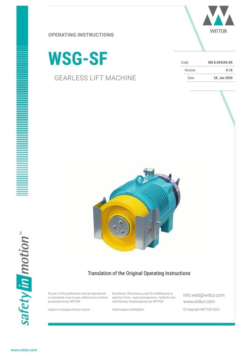
WITTUR safety in motion CORE CD User manual
WITTUR
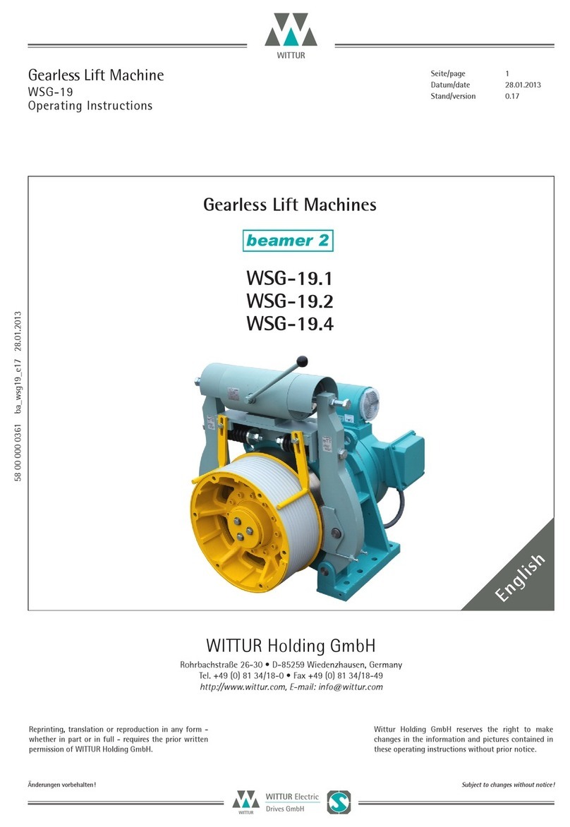
WITTUR WSG09 Operating instructions
WITTUR
WITTUR WGG-29.1 User manual

WITTUR
WITTUR OL35E-NA User manual

WITTUR
WITTUR WSG-10 Operating instructions

WITTUR
WITTUR WSG-W8 Series User manual

WITTUR
WITTUR WSG-18 Series User manual