DANPHONE Futronic MKII User manual

Futronic MKII
Maritime Communication Test Box
User manual
Version 9 November 2021
This manual supports software version
682.0001.042 (Master)
682.0002.037 (Application)
Klokkestoebervej 4. DK-9490 Pandrup. Denmark
Tel: +45 96 44 44 44, Fax: +45 96 44 44 45

Page 2 of 65
SCROLL MENU SYSTEM - QUICK GUIDE
See detailed menu tree on page 9.
Edit ship’s MMSI MMSI: 1234567890
Radio tests VHF Radios
MF/HF Radios
NAVTEX tests NAVTEX Receivers
AIS tests AIS Transponders & AtoNs
Beacon tests 406 MHz EPIRBs & PLBs
AIS-SARTs & MOB devices
Radar SARTs
Tests results Show results
Transfer to PC
Clear memory
Freq. Counter 0.4 - 475 MHz
Test Box settings Time & date
Backlight time
LCD contrast
OCXO time
Enable speaker
Test Box info Test Box model
Serial number
Software version
Calibration due date
Battery voltage
Self test PLL test
FRQ test

Page 3 of 65
INTRODUCTION
GMDSS TESTS
For the testing of VHF and MF/HF radios, the test box can check DSC signals transmitted on
any of the six distress frequencies on MF/HF and on VHF CH 70.
The test box can send either a GMDSS distress signal (all ships call) or a selective test call
addressed to a particular MMSI number. The calls can be sent on any of the 6 distress
frequencies on MF/HF as well as on VHF CH 70. Furthermore, the test box can send and
receive DSC signals on the international calling frequencies 2177.0 and 2189.5 kHz.
The test box measures and displays the mark/space frequencies of the received DSC-signals.
On VHF channel 6, 8, 9, 13 and 16 the test box can measure the deviation on a received signal.
The test box is able to measure the transmitted and reflected power on any VHF channel,
including CH 70, all Maritime MF/HF Bands (with optional accs. MF/HF Power Sensor) and also
to test the sensitivity of the receiver part.
For the testing of NAVTEX Receivers, the test box can send NAVTEX signals on 490 kHz,
518 kHz or 4209.5 kHz.
For the testing of TELEX Receivers, the test box can send TELEX signals on 2.1745 MHz,
4.1775 MHz, 6.2680 MHz, 12.520 MHz and 16.6950 MHz.
The test box can also be used to check 406 MHz EPIRBs and Personal Locator Beacons, as
it can receive and decode test calls on 406.025 / .028 / .031/ .037 /.040 MHz as well as receive
the 121.5 MHz homing signal.
AIS TESTS
The test box is capable of testing AIS Class A transponders for vessels, aircrafts and shore
stations as well as Class B Transponders by checking their ability of sending and receiving
AIS data and by making frequency measurements and power measurements on CH 70, AIS
channel 1 and AIS channel 2.
Furthermore, it is possible to check the GMDSS communication on CH 70 by requesting reports
of the ship’s call sign, IMO number, name, type, dimensions, draught and destination, etc.
The test box is able to simulate ships appearing at four different positions, relative to the AIS
transponder’s position.
The AIS test facility can also be used for the testing of AIS-SARTs, AtoN devices and
Man Over Board devices, as it can receive and decode test calls from these.
RADAR SART TESTS
For the testing of 9 GHz Radar SARTs, the test box measures the frequency of the response
signals transmitted from the SART and will display the average frequency.
This manual covers the full-featured test box model GMDSS-AIS-SART equipped for
GMDSS tests, AIS tests and Radar SART tests. If your test box does not include all these
features, you are kindly requested to disregard the related sections in this manual.

Page 4 of 65
TABLE OF CONTENTS
SCROLL MENU SYSTEM - QUICK GUIDE ...........................................................................1
INTRODUCTION....................................................................................................................3
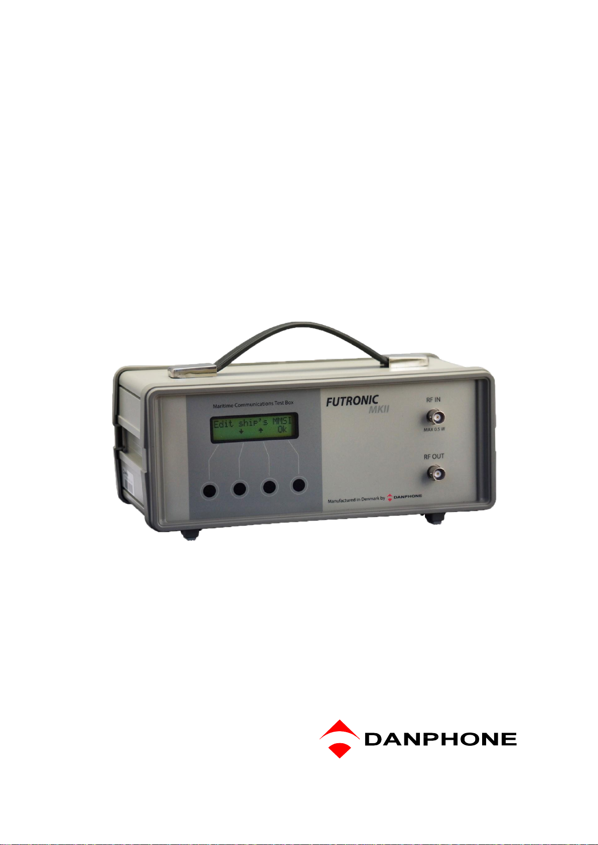
TEST BOX.............................................................................................................................6
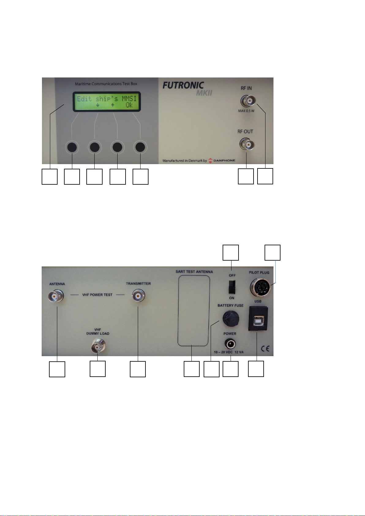
Front View..........................................................................................................................6
Rear View...........................................................................................................................6
ACCESSORIES.....................................................................................................................7
POWER SUPPLY ..................................................................................................................8
POWER-ON AND WARM-UP................................................................................................8
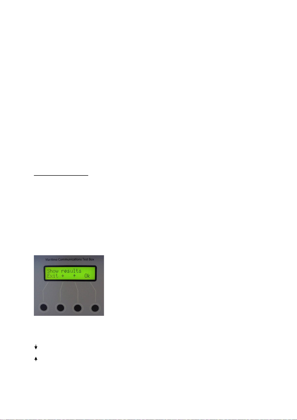
PUSH BUTTON CONTROL AND MENU SYSTEM................................................................8
MENU TREE..........................................................................................................................9
REMOTE CONTROL ...........................................................................................................13
EDIT SHIP’S MMSI ..............................................................................................................13
RADIO TESTS.....................................................................................................................15
VHF Radios......................................................................................................................15
Receive DSC................................................................................................................15
Receive DSC sele ........................................................................................................16
Send DSC ....................................................................................................................17
Send custom DSC........................................................................................................19
Receive ATIS................................................................................................................20
VHF power test.............................................................................................................20
VHF Frequency test......................................................................................................21
FM Deviation ................................................................................................................23
AM / 123.1 MHz...........................................................................................................24
Signal level...................................................................................................................24
Test sensitivity..............................................................................................................25
MF/HF Radios..................................................................................................................27
Receive DSC................................................................................................................27
Simultaneous MF/HF power test...................................................................................28
Send DSC ....................................................................................................................29
Send custom DSC........................................................................................................32
Signal level...................................................................................................................33
Test Sensitivity .............................................................................................................33
TELEX test...................................................................................................................33
MF/HF Power test.........................................................................................................34
NAVTEX TESTS ..................................................................................................................36
AIS TRANSPONDER TESTS...............................................................................................38
Receive AIS sele..........................................................................................................40
Receive AIS..................................................................................................................41
AIS auto test.................................................................................................................41
Receive AIS loop..........................................................................................................42
Receive Message 21 (AtoN).........................................................................................43
Poll info CH70...............................................................................................................43
Request Message 5 (Class A)......................................................................................44
Request Message 11 (UTC).........................................................................................44
Request Message 24 (Class B) ....................................................................................45
Send AIS message.......................................................................................................46

Page 5 of 65
Send custom AIS message...........................................................................................46
Simulate Ships..............................................................................................................47
Pilot Plug Test ..............................................................................................................47
BEACON TESTS .................................................................................................................49
406 MHz EPIRBs and Personal Locator Beacons............................................................49
EPIRB 121.5 MHz ........................................................................................................50
AIS-SARTs and Man Over Board Devices ...........................................................................52
Radar SARTs...................................................................................................................54
TEST RESULTS ..................................................................................................................56
Show results.................................................................................................................56
Transfer to PC..............................................................................................................56
Clear Memory...............................................................................................................56
Automatic generation of EPIRB reports via PC.............................................................57
FREQUENCY COUNTER.............................................................................................58
TEST BOX SETTINGS.........................................................................................................59
Time & date..................................................................................................................59
Backlight time...............................................................................................................59
LCD contrast.................................................................................................................59
OCXO time...................................................................................................................59
Enable speaker.............................................................................................................59
Return to Default Settings.............................................................................................59
TEST BOX INFO..................................................................................................................60
Test box model.............................................................................................................60
Serial number...............................................................................................................60
Software version...........................................................................................................60
Calibration due date......................................................................................................60
Battery voltage..............................................................................................................60
SELF TEST..........................................................................................................................60
TECHNICAL SPECIFICATIONS ..........................................................................................61
PERFORMANCE CHECK....................................................................................................61
RE-CALIBRATION SCHEDULE...........................................................................................62
DECLARATIONS .................................................................................................................62

Page 6 of 65
TEST BOX
Front View
1 Two-Line LCD display
2 –5 Push buttons
6 BNC socket for signal output
7 BNC socket for signal input
Rear View
1 BNC socket for connection to VHF antenna
2 BNC socket for connection of VHF dummy load
3 BNC socket for connection to VHF transmitter
4 RADAR-SART Antenna (If installed)
5 Fuse for 12V Battery. To be removed during transportation by air.
Type: 5x20mm 250V-2A “T”
6 DC socket for connection to external power supply
7 USB socket
8 8-pin DIN socket for connection to pilot plug
9 Slide switch for switching the test box ON/OFF
1
2
3
4
5
6
7
1
2
3
4
5
6
7
9
8

Page 7 of 65
ACCESSORIES
The test box comes with the following standard accessories:
1 pcs Power adapter 100-240 VAC / 13,2 VDC
1 - Cable for external DC power
incl. Cigar lighter plug
1 - USB cable for connection to PC
1 - Coax cable, 25 cm, with BNC
2 - Coax cable, 150 cm, with BNC
1 - Coax cable, 500 cm, with BNC
1 - AIS signal combiner / dummy load
1 - Audio Reference / AF Generator
1 - Telescopic antenna for VHF/AIS
1 - Wire antenna for MF/HF/NAVTEX
2 - UHF plug to BNC socket adapter
1 - UHF socket to BNC socket adapter
1 - BNC socket to BNC socket adapter
1 - User’s Manual in English
1 - Calibration Certificate
OPTIONAL ACCESSORIES
RF Amplifier
If the test box signal is not powerful enough when testing NAVTEX receivers and MF radios
over the air, adding this RF amplifier will increase the output level by 15-20 dB.
Watertight and Crush Proof Case
This case is specially configured to hold the tester and accessories safe and secure. Weight
only 3.9 kgs. External dimensions: 460 x 360 x 175 mm.
Backpack with protective cases
The waterproof backpack protects the test box and all accessories. It contains two
cases made of Polyethylene Foam to support and secure the equipment. The backpack
is ergonomic for back and shoulders and is easy and handy for transportation.
Set of Attenuators
Attenuators are used e.g. with AIS tests and VHF sensitivity tests. The set includes 1x10 dB,
1x20 dB and 1x40 dB attenuators, 2 Watt, with BNC.
Pilot Plug Cable
This cable is used with the testing of pilot plugs onboard ships. The cable is equipped with a
jack to fit standard pilot plugs.
MF/HF Power Sensor
This unit is used to measure the power extracted from the MF/HF radio on frequency 2MHz to
25.2MHz. The max. power is 500W PEP 2 min. Continuous 250W PEP.

Page 8 of 65
POWER SUPPLY
The test box is usually powered by the external power adapter delivered with the test box. The
adapter can be connected to 100-240 VAC and will provide DC power to the test box when
connected to the POWER socket on the rear panel. However, any power supply providing DC
between 10 and 28 VDC can be connected (+ on the center pin). For instance, a car charger
can be used, enabling the battery inside the test box to be recharged while driving your car.
The test box is equipped with a rechargeable 12 V battery. Whenever external DC is connected
to the test box, the battery is charged. If the DC supply is removed, the battery takes over,
ensuring an uninterrupted switch between external and internal power supply.
Before using the test box in the field, make sure that the battery is fully charged. Fully charged,
the battery should provide power for at least 8 hours of normal operation.
It is recommended from time to time to charge the battery over a full day and night. Also
recommended if the battery has been completely discharged. This will keep the battery fit and
fully restore its capacity.
Loss of power will not cause any loss of data in the test box memory.
During transport by air you are advised to remove the battery fuse from the rear panel. With
this, the test box is permitted as carry-on and check-in baggage. See the chapter
“Declarations”.
POWER-ON AND WARM-UP
When powered on, the tester’s model type and serial number is briefly presented the LCD-
display. After a few seconds of warming up the test box is ready for use.
PUSH BUTTON CONTROL AND MENU SYSTEM
The test box is controlled by means of 4 push buttons, each of them with a reference to the
bottom line of the display.
is used to scroll down to the next menu line, or to decrease numbers, frequencies etc.
is used to scroll up to the previous menu line, or to increase numbers, frequencies etc.
Ok is used to select or accept what’s in the upper line of the display
Exit is used to move one step back in the menu system.

Page 9 of 65
MENU TREE
Modes and menus, test setups and measurements are explained in more detail on page 12 and
onwards. As you may wish to test several sets in a row, for instance several radios under the
same MMSI, each set can be given its own individual number for recognition, for instance VHF
no. 3
Edit ship’s MMSI MMSI: 1234567890
Radio tests VHF Radios Set no.: Receive DSC
Receive DSC sele
Send DSC
Send custom DSC
Receive ATIS
VHF power test
Frequency test
FM deviation
AM / 123.1 MHz
Signal level
Test sensitivity
MF/HF Radios Set no.: Receive DSC
Send DSC
Send custom DSC
Signal level
Test sensitivity
TELEX test
MF/HF power test
(optional acc.)
NAVTEX tests Set no.: Send 490 kHz
Send 518 kHz
Send 4209.5 kHz

Page 10 of 65
MENU TREE (CONTINUED)
AIS tests Set no.: Receive AIS sele
Receive AIS
AIS auto test
Receive AIS loop
Receive MSG 21 (AtoN)
Poll info CH70
Request MSG 5 (Class A)
Request MSG 11 (UTC)
Request MSG 24 (Class B)
Send AIS MSG
Simulate ships
Beacon tests 406 MHz EPIRBs Set no.: Detect frequency
406.025 MHz
406.028 MHz
406.031 MHz
406.037 MHz
406.040 MHz
121.5 MHz
AIS-SARTs Set no.: Activate SART
Radar SARTs Set no.: Activate SART
Test results Show results
Transfer to PC
Clear memory
Pilot plug test

Page 11 of 65
MENU TREE (CONTINUED)
Freq. Counter 0.4 - 30 MHz
30 - 50 MHz
50 - 75 MHz
75 - 100 MHz
100 - 125 MHz
125 - 150 MHz
150 - 175 MHz
175 - 200 MHz
200 - 225 MHz
225 - 250 MHz
250 - 275 MHz
275 - 300 MHz
300 - 325 MHz
325 - 350 MHz
350 - 375 MHz
375 - 400 MHz
400 - 425 MHz
425 - 450 MHz
450 - 475 MHz

Page 12 of 65
MENU TREE (CONTINUED)
Test Box setting Time & date
Backlight time
LCD contrast
OCXO time
Enable speaker
Test Box info Test Box model
Serial number
Software version
Calibration due date
Battery voltage
Self test PLL test
FRQ test

Page 13 of 65
REMOTE CONTROL
The test box can be remote controlled from a PC.
Download the Futronic MKll manager PC software (remote control is supported from version
610.0019.002) Connect the test box to the PC via USB cable (standard accessory).
Remote control is supported on the test box from software versions (Master) 682.0001.036
(Application) 682.0002.032. See “Test Box info”.
Online software update is available on www.danphone.com/service-support/software-update/
All test box functions are available for remote control.
EDIT SHIP’S MMSI
You can check the current target MMSI number registered by the test box in the Edit ship’s
MMSI menu. In this menu you can either accept the current number or enter a new MMSI, if
required.
Press to move the cursor. Press ↑or ↓to change the digit. Press EXIT to accept and store
the number.
The test box is prepared for 10-digit numbers. If you enter a 9-digit number, add “0” in the end.
The test box will set the MMSI number automatically when performing the Receive DSC test for
VHF radios described under VHF radios, Receive DSC, on the following page.

Page 14 of 65
To save the new MMSI number press ”View”and thereafter, “Store”.
Futronic MKll manager
The Settings tab allows you to type in any MMSI number on the test box.
Test box MMSI: Write and set new MMSI number for the test box here.
Target MMSI: Write and set MMSI number of the device to be tested here.
When changing the Target MMSI, a new entry in Index is created in the test results.
If a new entry in Index is to be created, press the at Target MMSI “Set” button in FUTRONIC
MKII Manager. If the “Target MMSI” not changed, it’s only the timestamp which are changed
in the Index entry.
Another way of adding a new entry in Index is the “Edit ship’s MMSI” is used. A new entry is
created in the test results if a minimum 1 digit is changed.

Page 15 of 65
RADIO TESTS
VHF Radios
Set Number
As you may wish to test several radios under the same MMSI, each radio can be given its own
individual set number for recognition. Default number is 1. Press OK to confirm or press ↑or ↓
to change to another number. Then, press OK and go to the test you wish to perform.
Receive DSC
In the Receive DSC test mode, the test box will receive and display the radio’s MMSI number
and DSC data transmitted, and at the same time measure the frequency and the forwarded and
reflected power.
Use this setup with the Receive DSC test:
The test can also be performed over the dummy load inside the test box. If so, use the short
coax cable supplied with the test box and connect like this:
To perform the test, select Receive DSC and press OK and activate the transmitter to send a
DSC call.
The received MMSI number, DSC data and the measured frequency and power values will be
stored in the test box memory and at the same time appear in the LCD display, line by line.
You may toggle between the lines using ↑and ↓to view all the results.
DSC TRANSMITTER
DSC TRANSMITTER
ANT.
ANT.

Page 16 of 65
Example of Printout from the Memory:
VHF # 1 Time/date: 12:49:51 / 18-12-2019
DSC DATA: CH70-156.525 MHz
RX MMSI: 9999999990 Format 120 Category: 100 TX MMSI: 2195576240
1.telecommand: 100 2.telecommand: 126 Info.: 90 00 16 126 126 126
EOS: 117 ECC: 120 Status: OK
RF: 156,525.3 kHz Fwd.: 18.8 Watt Rev.: 0.1 Watt VSWR: 1.20
If you only want to check DSC data and frequency (no power measurement), connect the
telescopic VHF antenna to RF IN and use this setup:
If there are DSC transmissions from more than one radio in the area –for instance in ports with
many ships –the test box will receive data from the radio first detected.
To make sure that the test box will be receiving data from one particular radio, use the test
mode “Receive DSC sele” below.
Receive DSC sele
In the Receive DSC sele mode, the test box will receive data from the radio having its MMSI
number currently registered in the test box. So, please check and change number, if required,
using the Edit ship’s MMSI menu on page 12.
Use the same setup as above.
Example of Printout from the Memory:
VHF # 1 Time/date: 12:52:01 / 18-12-2019
DSC DATA: CH70-156.525 MHz
RX MMSI: 9999999990 Format 120 Category: 100 TX MMSI: 2195576240
1.telecommand: 100 2.telecommand: 126 Info.: 90 00 16 126 126 126
EOS: 117 ECC: 120 Status: OK
RF: 156,525.3 kHz
DSC TRANSMITTER
ANT.

Page 17 of 65
Generate 122 (Acknowledge back quote)
If a DSC message format 120 (Selective) and category 100 (Routine), 108 (Safety) or 110
(Urgency) and 117 (Ack. RQ) are received, the FUTRONIC MKII is able to generate a 122 (Ack.
BQ). After receiving the message, the message is shown on the display. When exiting the
results view, the following message is shown on the display.
Send Acknowledge
Skip Ack
Select Ack for transmitting the Ack. BQ message. Remember to connect the antenna to RF Out
on the Testbox.
Send DSC
In the Send DSC mode, the test box will transmit a DSC call for you to check on the DSC
receiver accordingly.
It is a requirement that the MMSI number registered in the test box is identical with the MMSI of
the radio to be tested. Please check and change number, if required, using the Edit ship’s MMSI
menu. See Page 12.
With selective calls, connect the telescopic VHF antenna to RF OUT and use this setup:
With distress calls, it is important to use a coax cable for the connection between the test box
and the DSC receiver. This will prevent other ship stations to be alerted.
Use this setup with distress calls:
DSC RECEIVER
ANT.
DSC RECEIVER
ANT.

Page 18 of 65
Select “Send DSC”and press “OK”.The DSC frequency will appear in the display. Select Dis
to send a distress call, Tst or Sel to send a selective call.
Following the DSC call, the test box will display Received status. Press “OK”if the call was
successfully received. Press “Fail”if the call was not well received. The answer will be stored in
the test box memory for your test report.
Tst - Send Safety Test call and wait for receiving Test call acknowledgement from the
transceiver.
Remember to connect both RF OUT and RF IN on the testbox.
Example of received Test call acknowledgement:
VHF # 1 Time/date: 08:29:25 / 29-01-2020
DSC DATA: CH70-156.525 MHz
RX MMSI: 9999999990 Format 120 Category: 108 TX MMSI: 2190155210
Test acknowledgement
EOS: 122 ECC: 66 Status: OK
RF: 156,525.1 kHz Fwd.: 22.3 Watt Rev.: 0.2 Watt VSWR: 1.24
The selective call transmits the following information:
120,120 Format specifier - individual call.
21,95,57,62,40 Address - 2195576240
100 Category - Routine
99,99,99,99,90 Self-identification = Testbox “MMSI no”.
100 First telecommand
126 Second telecommand
90 0 6 90 0 6 Frequency or channel
117 Ack. RQ - End of sequence
76 Modulus-2 checksum
The distress call transmits the following information:
112, 112 Format specifier - Distress call
99,99,99,99,90 Testbox “MMSI no”.
107 Category - Undesignated distress
99,99,99,99,99 Coordinates - 99 99 99 99 99 at test.
88,88 Time - 88 88 at test.
100 First telecommand
127 EOS - End of sequence
57 Modulus-2 checksum

Page 19 of 65
The Test Safety call transmits the following information:
120,120 Format specifier - individual call
21,90,15,52,10 Address - 2190155210
108 Category - Safety
99,99,99,99,90 Self-identification = Testbox "MMSI no".
118 First telecommand - Test
126 Second telecommand - No information
126,126,126,126,126,126 No information
117 Ack. RQ - End of sequence
77 Modulus-2 checksum
Send custom DSC
The Send custom DSC mode enables the test box to send a custom-made DSC call composed
in advance on a PC using Futronic MKll manager. Connect your PC to the test box via the USB
cable supplied.
Futronic MKll manager
Under the “DSC Composer” tab you can compose your own custom-made DSC messages and
transfer them to the test box accordingly.
Please refer to ITU-R M.493 for composing of DSC messages.
In the section, Transfer message to the test box, select “VHF”.
Custom-made DSC messages can also be saved on your PC for later use.

Page 20 of 65
Futronic MKll test box
To make the test box transmit the custom-made call, select “Send custom DSC”on the test
box. The DSC frequency will appear in the display. Press “OK”again to send the call.
Following the DSC call, the test box will display Received status. Press “OK”if the call was
successfully received. Press “Fail”if the call was not well received. The answer will be stored in
the test box memory for your test report.
Receive ATIS
ATIS (Automatic Transmitter Identification System) is a signaling protocol used on the inland
waterways of Europe that enables the authorities to identify each transmission by a short data
burst sent when the PTT key is released.
In the Receive ATIS mode, keying of an ATIS equipped VHF on CH 6 or CH 15 will enable the
test box to receive the station’s ID.
Use this setup:
Select “Receive ATIS”on the test box and press “OK”. Select channel and press “OK”. Then,
activate the ATIS transmitter.
The test box will receive and display the transmitter’s ID and at the same time store it in the test
box memory.
VHF power test
The VHF power test mode is used to measure the transmitted and the reflected power from
non-DSC VHF radios.
Use this setup with the VHF Power test:
VHF TRANSMITTER
ANT.
VHF ATIS TRANSMITTER
ANT.
Other manuals for Futronic MKII
1
Table of contents
Other DANPHONE Test Equipment manuals