DAPAudio COM-42 User manual

COM-42 2Ch Handheld set
Highlite International B.V. –Vestastraat 2 –6468 EX –Kerkrade –the Netherlands
Product code: D1464
USER MANUAL
ENGLISH
V2

1
COM-42 2Ch Handheld set
Product code: D1464
Preface
Thank you for purchasing this DAP product.
The purpose of this user manual is to provide instructions for the correct and safe use of this product.
Keep the user manual for future reference as it is an integral part of the product. The user manual shall be
stored at an easily accessible location.
This user manual contains information concerning:
●Safety instructions
●Installation and operation of the device
●Intended and non-intended use of the device
●Maintenance procedures
●Troubleshooting
●Transport, storage and disposal of the device
Non-observance of the instructions in this user manual may result in serious injuries and damage of
property.
©2023 DAP. All rights reserved.
No part of this document may be copied, published or otherwise reproduced without the prior written
consent of Highlite International.
Design and product specifications are subject to change without prior notice.
For the latest version of this document or other language versions, please visit our website
www.highlite.com or contact us at service@highlite.com.
Highlite International and its authorized service providers are not liable for any injury, damage, direct or
indirect loss, consequential or economic loss or any other loss arising from the use of, or inability to use or
reliance on the information contained in this document.

2
COM-42 2Ch Handheld set
Product code: D1464
Table of contents
1. Introduction..........................................................................................................................................................3
Before Using the Product ..................................................................................................................................3
Intended Use .......................................................................................................................................................3
Product Lifespan.................................................................................................................................................3
Text Conventions ................................................................................................................................................3
Symbols and Signal Words................................................................................................................................4
Symbols on the Information Label ..................................................................................................................4
2. Safety ....................................................................................................................................................................5
Warnings and Safety Instructions ....................................................................................................................5
Requirements for the User.................................................................................................................................6
3. Description of the Device ...................................................................................................................................7
Receiver –Front View ........................................................................................................................................7
Receiver –Back View ........................................................................................................................................7
Handheld Transmitter (Microphone) ..............................................................................................................8
Product Specifications ......................................................................................................................................9
Optional Accessories.......................................................................................................................................10
Dimensions.........................................................................................................................................................11
4. Installation and Setup .......................................................................................................................................12
Ambient Conditions .........................................................................................................................................12
Receiver Installation and Setup.....................................................................................................................12
Mounting ..................................................................................................................................................12
Installation of the Antennas..................................................................................................................12
Connecting to Power Supply...............................................................................................................12
Transmitter Setup ..............................................................................................................................................13
Installation of the Batteries ...................................................................................................................13
Pairing.................................................................................................................................................................14
Connecting the Receiver to Mixer/Amplifier..............................................................................................15
5. Operation ...........................................................................................................................................................16
Receiver Switching ON/OFF...........................................................................................................................16
Transmitter Switching ON/OFF .......................................................................................................................16
Operation ..........................................................................................................................................................17
Muting the Transmitter ...........................................................................................................................17
Transmitter Mute LED Indicator Statuses ......................................................................................................17
Receiver Display Indications ..........................................................................................................................17
Channels Overview .........................................................................................................................................18
6. Troubleshooting .................................................................................................................................................19
Adjusting the Microphone Gain....................................................................................................................20
Adjusting the Squelch Threshold ...................................................................................................................20
7. Maintenance .....................................................................................................................................................21
Preventive Maintenance................................................................................................................................21
Basic Cleaning Instructions ...................................................................................................................21
Corrective Maintenance................................................................................................................................21
8. Deinstallation, Transportation and Storage ....................................................................................................22
9. Disposal ..............................................................................................................................................................22
10. Approval.............................................................................................................................................................22

3
COM-42 2Ch Handheld set
Product code: D1464
1. Introduction
Before Using the Product
Important
Read and follow the instructions in this user manual before installing, operating or
servicing this product.
The manufacturer will not accept liability for any resulting damages caused by the non-observance of
this manual.
After unpacking, check the contents of the box. If any parts are missing or damaged, contact your
Highlite International dealer.
Your shipment includes:
●DAP COM-42 wireless receiver
●2 handheld wireless
transmitters
●AC power adapter
●2 antennas
●Mono jack cable
●Microphone stickers
●User manual
Fig. 01
Intended Use
This device is intended for use as a wireless microphone system. It is suitable only for indoor installation.
Any other use, not mentioned under intended use, is regarded as non-intended and incorrect use.
Product Lifespan
This device is not designed for permanent operation. Disconnect the device from the electrical power
supply when the device is not in operation. This will reduce the wear and will improve the device’s
lifespan.
Text Conventions
Throughout the user manual the following text conventions are used:
●References: References to chapters and parts of the device are in bold lettering, for example:
“Refer to 2. Safety”, “press the power switch (03)”
●0–255: Defines a range of values
●Notes: Note: (in bold lettering) is followed by useful information or tips

4
COM-42 2Ch Handheld set
Product code: D1464
Symbols and Signal Words
Safety notes and warnings are indicated throughout the user manual by safety signs.
Always follow the instructions provided in this user manual.
DANGER
Indicates an imminently hazardous situation which, if not avoided, will result in
death or serious injury.
WARNING
Indicates an imminently hazardous situation which, if not avoided, could result
in death or serious injury.
CAUTION
Indicates a potentially hazardous situation, which, if not avoided, may result in
minor or moderate injury.
Attention
Indicates important information for the correct operation and use of the
product.
Important
Read and observe the instructions in this document.
Provides important information about the disposal of this product.
Symbols on the Information Label
This product is provided with an information label. The information label is located on the bottom plate of
the device.
The information label contains the following symbols:
This device shall not be treated as household waste.

5
COM-42 2Ch Handheld set
Product code: D1464
2. Safety
Important
Read and follow the instructions in this user manual before installing, operating or
servicing this product.
The manufacturer will not accept liability for any resulting damages caused by the non-observance of
this manual.
Warnings and Safety Instructions
DANGER
Danger for children
For adult use only. The device must be installed beyond the reach of children.
●Do not leave various parts of the packaging (plastic bags, polystyrene foam, nails, etc.) within
children’s reach. Packaging material is a potential source of danger for children.
Attention
Incorrect handling of the AC power adapter may result in hazardous situations
This device is delivered with an AC power adapter. Incorrect handling of the AC power adapter may
result in hazardous situations.
●Use only the AC power adapter delivered with the device.
●Do not wrap the power cable around the power adapter or any other object. This can damage the
internal wires.
●Do not cover the power adapter with anything when it is plugged into the socket-outlet. This may
cause overheating.
●Do not expose the power adapter to water or other liquids.
Do not use the power adapter:
●If it shows signs of overheating, for example the plastic is damaged
●If the AC input pins show signs of corrosion or overheating
●If the power cable is damaged or shows signs of material fatigue.
Attention
General safety
●Do not shake the device. Avoid brute force when installing or operating the device.
●If the device is exposed to extreme temperature variations (e.g. after transportation), do not switch it
on immediately. Let the device reach room temperature before switching it on, otherwise it may be
damaged by the formed condensation.

6
COM-42 2Ch Handheld set
Product code: D1464
Attention
This device shall be used only for the purposes it is designed for.
This device is designed to be used as a wireless microphone system. Any incorrect use may lead to
hazardous situations and result in injuries and material damage.
This device does not contain user-serviceable parts. Unauthorized modifications to the device will render
the warranty void. Such modifications may result in injuries and material damage.
Attention
Do not expose the device to conditions that exceed the rated IP class conditions.
This device is IP20 rated. IP (Ingress Protection) 20 class provides protection against solid objects greater
than 12 mm, such as fingers, and no protection against harmful ingress of water.
Requirements for the User
This product may be used by ordinary persons. Maintenance and installation may be carried by ordinary
persons. Service shall be carried out only by instructed or skilled persons. Contact your Highlite
International dealer for more information.
Instructed persons have been instructed and trained by a skilled person, or are supervised by a skilled
person, for specific tasks and work activities associated with the service of this product, so that they can
identify risks and take precautions to avoid them.
Skilled persons have training or experience, which enables them to recognize risks and to avoid hazards
associated with the service of this product.
Ordinary persons are all persons other than instructed persons and skilled persons. Ordinary persons
include not only users of the product but also any other persons that may have access to the device or
who may be in the vicinity of the device.

7
COM-42 2Ch Handheld set
Product code: D1464
3. Description of the Device
The DAP COM-42 2Ch Handheld set is a wireless microphone system consisting of a wireless receiver and
2 handheld wireless transmitters. The wireless receiver is equipped with 2 balanced XLR outputs and an
unbalanced ¼” TRS jack output.
Receiver –Front View
Fig. 02
Volume control (CH A)
UP button (CH A)
DOWN/PAIR button (CH A)
LCD display
DOWN/PAIR button (CH B)
UP button (CH B)
Volume control (CH B)
Power button
IR sensor (receiver)
Receiver –Back View
Fig. 03
10) BNC connector (antenna B)
11) DC input connector, 15 V DC, 300 mA
12) Squelch B control
13) XLR connector B OUT, balanced
¼ʺTRS jack connector OUT(A+B), unbalanced
XLR connector A OUT, balanced
Squelch A control
BNC connector (antenna A)

8
COM-42 2Ch Handheld set
Product code: D1464
Handheld Transmitter (Microphone)
Fig. 04
18) Mute LED indicator
19) ON/OFF button
20) Gain control
21) IR sensor (transmitter)
22) Plastic mini screwdriver
23) Microphone housing
Microphone body
Battery compartment lock
Battery compartment
Battery compartment cover

9
COM-42 2Ch Handheld set
Product code: D1464
Product Specifications
Model:
COM-42 2Ch Handheld set
Receiver
Electrical:
Input voltage:
15 V DC
Input current:
0,3 A
Power consumption:
15 W
Physical:
Dimensions:
210 x 210 x 45 mm (L x W x H)
Installation depth:
210 mm
Weight:
1 kg
Radio specifications:
Frequency range:
606–630 MHz
Frequency response:
50–16000 Hz
Frequency deviation:
± 225 kHz
Stability:
0,005 %
RF power:
10 mW
RF bandwidth:
24 MHz
Maximum SPL:
135 dB
Spurious rejection:
> 50 dB
THD level:
< 1,0 %
Signal-to-noise ratio:
> 100 dB
Connections:
Power connection:
DC input connector
Output connections:
2 x 3-pin XLR output connectors, balanced
¼” TRS jack output (A+B), unbalanced
Input RF connections:
2 BNC sockets
Operation and control:
Receiver type:
True diversity
Channels:
100
Display:
LCD
Construction:
Housing:
Aluminum
Color:
Black
IP rating:
IP20
Cooling:
Natural heat dissipation
Transmitter
Audio specifications:
Microphone type:
Dynamic moving coil
Sensitivity:
2,2 mV
Dynamic range:
100 dB
Polar pattern:
Cardioid
Operation and control:
ON/OFF switch:
yes
Batteries:
2 x AA, 1,5 V (not included)

10
COM-42 2Ch Handheld set
Product code: D1464
Physical:
Dimensions:
Ø50 x 260 mm (W x H)
Installation depth:
210 mm
Weight:
0,27 kg
Color:
Black
AC power adapter:
Input voltage:
100–240 V AC, 50/60 Hz
Input current:
0,4 A max
Output voltage:
15 V DC
Output current:
0,8 A
Thermal:
Maximum ambient temperature ta:
40 °C
Optional Accessories
The receiver can be mounted in a 19-inch rack. The device is delivered without a rack mount kit. The rack
mount kit can be purchased separately. Contact your Highlite International dealer for more information.
Product code: D1466 (Rackmount for 1 pc COM-42)

11
COM-42 2Ch Handheld set
Product code: D1464
Dimensions
Fig. 05
Fig. 06
Fig. 07

12
COM-42 2Ch Handheld set
Product code: D1464
4. Installation and Setup
Ambient Conditions
●The device can be used only indoors.
●The maximum ambient temperature ta= 40 °C must never be exceeded.
●The relative humidity must not exceed 50 % with an ambient temperature of 40 °C.
Receiver Installation and Setup
Mounting
The receiver can be placed on a stable, flat surface, or mounted in a standard 19-inch rack. See
3.5. Optional Accessories on page 10 for more information. The receiver requires 1 rack unit (U) of space,
which is 44,45 mm high.
Make sure that the rack is sufficiently secured to prevent it from becoming unstable or falling over.
Installation of the Antennas
The device is delivered with 2 antennas. The antennas are not connected. To install the antennas:
01) Insert the 1st antenna into BNC connector (antenna A) (17).
02) Insert the 2nd antenna into BNC connector (antenna B) (10).
03) Swivel the antennas in upright position.
Connecting to Power Supply
Attention
Incorrect handling of the AC power adapter may result in hazardous situations
This device is delivered with an AC power adapter. Incorrect handling of the AC power adapter may
result in hazardous situations.
●Connect the receiver to the socket-outlet with the delivered AC power adapter. Use only the AC
power adapter delivered with the device.
●Make sure that the socket-outlet is easily accessible.
●Disconnect the AC power adapter from the socket-outlet when the device is not in use.

13
COM-42 2Ch Handheld set
Product code: D1464
Transmitter Setup
Installation of the Batteries
The microphone is delivered without batteries. It accepts 2 LR6 (alkaline) AA batteries.
To install the batteries:
01) Turn the microphone housing (23)counterclockwise and remove it from the microphone body (24).
See Fig. 08.
02) Press the battery compartment lock (25) with one hand and the same time pull the battery
compartment cover (27) with the other hand to open the battery compartment cover (27). See
Fig. 09.
Fig. 08
Fig. 09
Insert the batteries into the battery compartment (26). The transmitter operates with 2 LR6 (alkaline)
AA batteries. The batteries are not delivered with the product.
Note:
Make sure that you install the batteries with correct polarity orientation.
Close the battery compartment cover (27).
Place the microphone housing (23) on the microphone body (24) and turn it clockwise to tighten it.
Note:
The mute LED indicator (18) starts blinking in red when the battery capacity is low. Change the batteries
to continue operation.

14
COM-42 2Ch Handheld set
Product code: D1464
Pairing
The receiver can be paired with two transmitters: one transmitter on channel A (CH A) and the other
transmitter on channel B (CH B). The receiver and the transmitters must be set to the same channel.
Otherwise the wireless system will not work correctly. For more information about the frequencies per
channel, see 5.6. Channels Overview on page 18.
To pair the transmitter to the receiver:
01) Switch on the receiver. See 5.1. Receiver Switching ON/OFF on page 16.
02) Switch on the transmitter. See 5.2. Transmitter Switching ON/OFF on page 16.
03) Remove the microphone housing (23) from the microphone body (24).
04) Position the transmitter at a distance of about 15–30 cm from the receiver. Make sure that the IR
sensor (21) on the transmitter is facing the IR sensor (09) on the receiver.
05) Select an available channel with the UP buttons (02)/(06) and the DOWN/PAIR buttons (03)/(05). The
selection range is 00–99.
Notes:
●Press and hold down the UP button (02)/(06) to fast forward to the next available channel.
●Press and hold down the DOWN/PAIR button (03)/(05) to fast backward to the previous available
channel.
06) Press and hold the UP and the DOWN/PAIR buttons for the respective channel A or B for 2 seconds to
send the channel information to the transmitter. The transmitter and the receiver are paired. The RF
indicator bar for the respective channel on the LCD display (04) lights up. The selected channel and
the channel frequency show on the LCD display (04). See 5.5. Receiver Display Indications on
page 17 and 5.6. Channels Overview on page 18 for more information.
07) Place the microphone housing (23) on the microphone body (24) and turn it clockwise to tighten it.

15
COM-42 2Ch Handheld set
Product code: D1464
Connecting the Receiver to Mixer/Amplifier
Attention
Connect all data cables before supplying power.
Disconnect power supply before connecting or disconnecting data cables.
The receiver has 2 balanced XLR output connectors and 1 unbalanced ¼ ʺTRS jack output connector.
Fig. 10
To connect the receiver to a mixer or an amplifier:
01) Make sure that the receiver is not connected to power supply and the volume is turned down.
Make sure that the mixer or the amplifier are switched off and the volume is turned down.
Use a 3-pin XLR audio cable to connect the XLR connectors A/B OUT (13)/(15) of the receiver to the
XLR input connectors of the mixer. As an alternative use a ¼ ʺmono jack cable to connect the
¼ ʺTRS jack connector OUT (14) of the receiver to the input connector of the amplifier.

16
COM-42 2Ch Handheld set
Product code: D1464
5. Operation
Attention
This device must be used only for the purposes it is designed for.
This device is intended for use as a wireless microphone system. It is not suitable for households.
Any other use, not mentioned under intended use, is regarded as non-intended and incorrect use.
Receiver Switching ON/OFF
The receiver has a power button.
●Press and hold down the power button (08) for 2 seconds to switch on the receiver. The LCD display
(04) lights up.
●When the receiver is switched on, press and hold down the power button (08) for 2 seconds to switch
off the receiver. The frequency indication on the LCD display (04) turns off. The receiver remains
energized.
Note:
The mains plug is used as a disconnect device. Disconnect the AC power adapter from the socket-outlet
to disconnect the receiver from the power supply.
Transmitter Switching ON/OFF
The transmitter has an ON/OFF button.
●Press and hold down the ON/OFF button (19) for 2 seconds to switch on the transmitter. The mute LED
indicator (18) lights up in green.
●When the transmitter is switched on, press and hold down the ON/OFF button (19) for 2 seconds to
switch off the transmitter. The mute LED indicator (18) turns off.

17
COM-42 2Ch Handheld set
Product code: D1464
Operation
To operate the wireless microphone system:
01) Complete the installation of the receiver. See 4.2.1. Mounting on page 12 and 4.2.2. Installation of
the Antennas on page 12.
02) Complete the setup of the transmitter(s). See 4.3. Transmitter Setup on page 13.
03) Complete the pairing of the receiver and the transmitter(s). See 4.4. Pairing on page 14.
04) Connect the receiver to a mixer or an amplifier. See 4.5. Connecting the Receiver to Mixer/Amplifier
on page 15.
05) Connect the receiver to power supply. See 4.2.3. Connecting to Power Supply on page 12.
06) Switch on the receiver. See 5.1. Receiver Switching ON/OFF on page 16.
07) Switch on the connected mixer/amplifier.
08) Turn up completely the volume of the receiver with the volume controls (01)/(07).
09) Switch on the transmitter. See 5.2. Transmitter Switching ON/OFF on page 16.
10) Talk or sing into the microphone. The AF indicator bar on the LCD display (04) of the receiver lights
up. The AF indicator bar increases or decreases during talking/singing.
11) Slowly turn up the volume on the connected mixer/amplifier to the desired level.
After use, switch off the receiver and the transmitter(s). See 5.1. Receiver Switching ON/OFF and 5.2.
Transmitter Switching ON/OFF on page 16 for more information.
Muting the Transmitter
During operation you can mute the transmitter with the ON/OFF button (19).
●Press the ON/OFF button (19) to mute the transmitter. The mute LED indicator (18) lights up in red.
●When the transmitter is muted, press the ON/OFF button (19) to unmute the transmitter. The mute LED
indicator (18) lights up in green.
Transmitter Mute LED Indicator Statuses
The mute LED indicator (18) on the transmitter has the following statuses:
●Green: normal operation
●Red: the transmitter is muted
●Flashing red: battery low
Receiver Display Indications
The LCD display (04) on the receiver shows the following information for channel A (CH A) and channel B
(CH B):
Fig. 11
A) Selected channel –for more information see 5.6. Channels Overview on page 18
B) AF indicator bar –shows the strength of the audio signal during operation
C) RF indicator bar –shows the strength of the radio signal during operation
D) Channel frequency –for more information see 5.6. Channels Overview on page 18

18
COM-42 2Ch Handheld set
Product code: D1464
Channels Overview
The carrier frequency is in the range 606–630 MHz.
CH
Frequency (MHz)
CH
Frequency (MHz)
CH
Frequency (MHz)
CH
Frequency (MHz)
0
606.125
25
611.750
50
617.375
75
623.000
1
606.350
26
611.975
51
617.600
76
623.225
2
606.575
27
612.200
52
617.825
77
623.450
3
606.800
28
612.425
53
618.050
78
623.675
4
607.025
29
612.650
54
618.275
79
623.900
5
607.250
30
612.875
55
618.500
80
624.125
6
607.475
31
613.100
56
618.725
81
624.350
7
607.700
32
613.325
57
618.950
82
624.575
8
607.925
33
613.550
58
619.175
83
624.800
9
608.150
34
613.775
59
619.400
84
625.025
10
608.375
35
614.000
60
619.625
85
625.250
11
608.600
36
614.225
61
619.850
86
625.475
12
608.825
37
614.450
62
620.075
87
625.700
13
609.050
38
614.675
63
620.300
88
625.925
14
609.275
39
614.900
64
620.525
89
626.150
15
609.500
40
615.125
65
620.750
90
626.375
16
609.725
41
615.350
66
620.975
91
626.600
17
609.950
42
615.575
67
621.200
92
626.825
18
610.175
43
615.800
68
621.425
93
627.050
19
610.400
44
616.025
69
621.650
94
627.275
20
610.625
45
616.250
70
621.875
95
627.500
21
610.850
46
616.475
71
622.100
96
627.725
22
611.075
47
616.700
72
622.325
97
627.950
23
611.300
48
616.925
73
622.550
98
628.175
24
611.525
49
617.150
74
622.775
99
628.400

19
COM-42 2Ch Handheld set
Product code: D1464
6. Troubleshooting
This troubleshooting guide contains solutions to problems which can be carried out by an ordinary
person. The device does not contain user-serviceable parts.
Unauthorized modifications to the device will render the warranty void. Such modifications may result in
injuries and material damage.
Refer servicing to instructed or skilled persons. Contact your Highlite International dealer in case the
solution is not described in the table.
Problem
Probable cause(s)
Solution
The devices do not
function at all
No power to the devices
●Make sure that the receiver is switched
on and connected to power supply
●Make sure that the batteries in the
transmitter are inserted correctly
The batteries in the transmitter are
depleted
●Change the batteries. See 4.3.1.
Installation of the Batteries on page 13
No sound
The transmitter is switched off or
does not function correctly
●Make sure that the transmitter is
switched on and the batteries are not
depleted
The transmitter is muted
●Make sure the transmitter is not muted
The volume is too low
●Turn up the volume on the receiver
●Make sure that the volume on the
connected devices is turned up
Channel selection
●Make sure that the receiver and the
transmitter are paired. See 4.4. Pairing
on page 14
The transmitter is out of range
●Move the transmitter closer to the
receiver
Connections are defective
●Examine connections and cables.
Correct defective connections. Repair
or replace damaged cables
The connected mixer or amplifier
does not function correctly
●Make sure that the connected mixer or
amplifier is switched on and functions
correctly
Bursts of noise or other
audible signals
present
Sources of interference are present
●Adjust the squelch threshold. See 6.2.
Adjusting the Squelch Threshold on
page 20
●Change the channel frequency
●Identify potential sources of
interference (other RF-sources) and turn
them off
Other manuals for COM-42
1
This manual suits for next models
1
Table of contents
Other DAPAudio Microphone System manuals

DAPAudio
DAPAudio EDGE EHS-1 User manual

DAPAudio
DAPAudio COM-2.4 User manual

DAPAudio
DAPAudio EDGE EBS-1 V2 User manual

DAPAudio
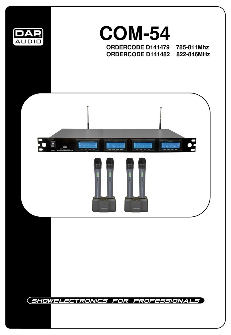
DAPAudio COM-54 User manual

DAPAudio
DAPAudio COM-31 Guitarist User manual

DAPAudio
DAPAudio IEM-100 Beltpack User manual

DAPAudio
DAPAudio EDGE EHS-2 User manual

DAPAudio
DAPAudio DM-25 User manual

DAPAudio
DAPAudio D141473 User manual

DAPAudio
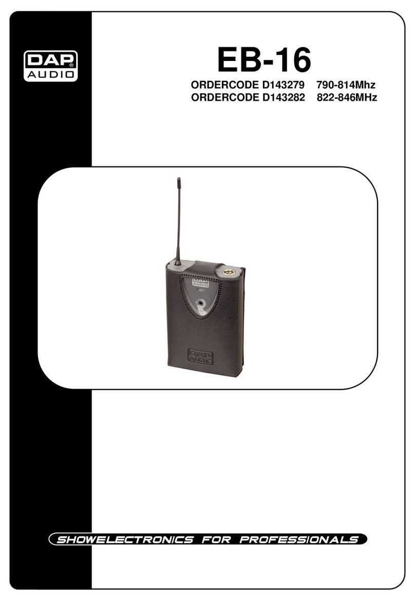
DAPAudio EB-16 User manual