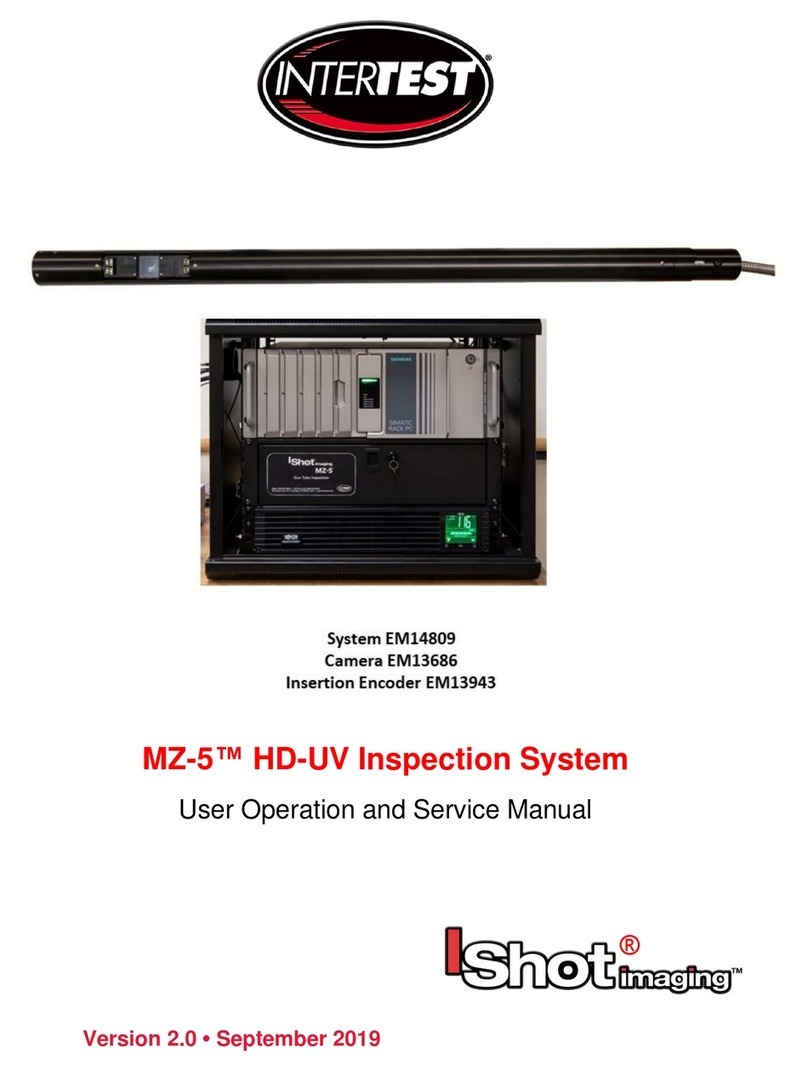
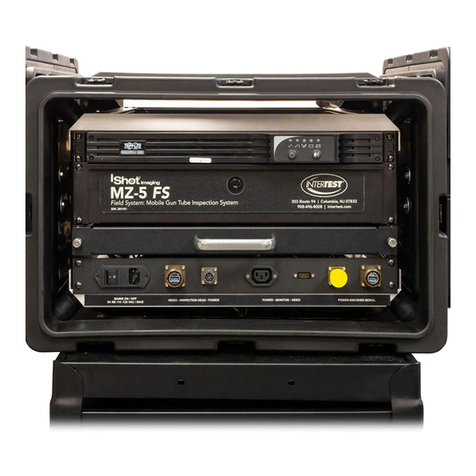
InterTest SeeUV VIBES EM18076 User manual

SeeUV® VIBES® Shaft & Coupler Inspection System (SCIS)
Instruction & Admin Manual
EM18076 SeeUV®Pole Cam HD Sys. w/ Motorized H & V
EM13068 Fixture for Coupler + Shaft GTF1100

SeeUV®Shaft & Coupler Inspection System (SCIS) Instruction & Admin Manual
Page 2of 43
InterTest, Inc. • 303 Route 94 • Columbia, NJ 07832
+1 (908) 496-8008 • service@intertest.com • www.intertest.com July 2023
Table of Contents
Contact Information.................................................................................................................................4
Introduction:..............................................................................................................................................4
Cautions and Sarnings...........................................................................................................................5
Safety Precautions ..............................................................................................................................5
Operational, General Safety Considerations and Precautions ....................................................5
Cautionary Symbols and Symbol Terminology...............................................................................5
Warnings...............................................................................................................................................6
Care & Maintenance ...........................................................................................................................6
Disclaimers ...........................................................................................................................................7
Warranty ...................................................................................................................................................7
Copyrights and Rights of Portrait..........................................................................................................8
Registered Trademark Information.......................................................................................................8
System Components ..............................................................................................................................9
Camera Control Unit, Light Sources, Monitor, On-Screen Display Unit & Cart.........................9
Standard ................................................................................................ 9
Optional ............................................................................................... 10
Available Optical Adapters / Tips.................................................................. 12
Tip Installation........................................................................................ 14
Light Source Connections....................................................................................................................14
Camera Controls ...................................................................................................................................16
Pole Cam Controller..............................................................................................................................17
Optical Tip Presets............................................................................................................................18
General Operation.................................................................................................................................18
Pole Mounting & System Connections...........................................................................................20
Optional Coupler/Shaft Fixture........................................................................................................21
Coupler Setup One .................................................................................. 22
Setup Steps (Coupler) .............................................................................. 22
Coupler Setup Two .................................................................................. 23
Shaft Setup One ..................................................................................... 24
Setup Steps (Shaft).................................................................................. 24
Shaft Setup Two ..................................................................................... 24
Pole Cam Cart System Controller .....................................................................................................26
Insertion Encoder Operation ...............................................................................................................28
Camera Control Unit Menu Structure.................................................................................................29

SeeUV®Shaft & Coupler Inspection System (SCIS) Instruction & Admin Manual
Page 3of 43
InterTest, Inc. • 303 Route 94 • Columbia, NJ 07832
+1 (908) 496-8008 • service@intertest.com • www.intertest.com July 2023
Menu Tree ..........................................................................................................................................29
Image Quality .....................................................................................................................................30
More Image Quality...........................................................................................................................30
Capture Setup (Not Used in Pole Cam).........................................................................................30
Utility Menu .........................................................................................................................................31
System Diagnostic.............................................................................................................................31
Save Setup .........................................................................................................................................32
Load Presets (Not used in Pole Cam)............................................................................................32
Lens Correction..................................................................................................................................32
Pan Tilt Zoom Menu..........................................................................................................................33
Set to defaults ....................................................................................................................................33
Shutter Table: ........................................................................................ 34
Specifications.........................................................................................................................................34
Camera Head.....................................................................................................................................34
Camera Cable ....................................................................................................................................35
Camera Control Unit (CCU).............................................................................................................35
Cart System........................................................................................................................................36
Optical Adapters (Tips).....................................................................................................................36
Controller & Camera Mechanical Specifications ..........................................................................37
Imager Control Menu Values & Defaults .......................................................................................38
Table of Figures.....................................................................................................................................40
Care & Maintenance.............................................................................................................................40
Overall System...................................................................................................................................40
Trouble Shooting ...................................................................................................................................40
Returns for Repair or Service ..........................................................................................................41
Return Evaluation Procedure ..........................................................................................................41
Parts and Accessories..........................................................................................................................42
NOTES:...................................................................................................................................................43

SeeUV®Shaft & Coupler Inspection System (SCIS) Instruction & Admin Manual
Page 4of 43
InterTest, Inc. • 303 Route 94 • Columbia, NJ 07832
+1 (908) 496-8008 • service@intertest.com • www.intertest.com July 2023
Contact Information
Corporate Headquarters
InterTest, Inc.
303 Route 94
Columbia, NJ 07832 USA
Telephone (USA and Canada): 800-535-3626
Telephone (Outside the USA and Canada): 908-496-8008
Facsimile: 908-496-8004
Visit us on the Internet
www.intertest.com
General Information via Email
InterTest, Inc. © 2023 All rights reserved.
Introduction:
Congratulations on your investment in the SeeUV®Shaft & Coupler Inspection System (SCIS),
InterTest’s one-inch diameter ultraviolet and white light visual inspection and bore examination system
(VIBES®). This system combines a high-definition color camera with mechanical, robust, and
repeatable positioning hardware for the visual inspection of shafts and coupler components inside
aircraft and aerospace engines. An operator can conduct on-the-spot white light, magnetic particle,
and fluorescent penetrant inspections of intricate components with minimal fixturing.
The SeeUV®Shaft & Coupler Inspection System will be referred to as the “SCIS,” but may include
such descriptions as “Pole Cam” and/or “Pole Cam HD.” Pole Cam and/or Pole Cam HD refers
specifically to the camera hardware mounted on the cart.
Many features enhance SCIS performance and versatility these include:
Generous Movement Envelope
Controlled by either hand or with optional motors, the camera boom travel is 51 inches* horizontally
and 16 inches* vertically.
*movement options in vertical, horizontal, or rotational movement available.
Illumination Control
SCIS has both white and UV light capability. Intensity is controlled independently and operation can be
UV, white, or both simultaneous.
Video Camera
The SCIS has motor driven remote controlled focus to ensure crisp, high- definition video images. They
capture color video at a resolution of 1920 x 1080 pixels with selectable output formats DVI 1080/30 fps,
720/60 fps or VGA/120 fps.

SeeUV®Shaft & Coupler Inspection System (SCIS) Instruction & Admin Manual
Page 5of 43
InterTest, Inc. • 303 Route 94 • Columbia, NJ 07832
+1 (908) 496-8008 • service@intertest.com • www.intertest.com July 2023
High-Definition Color Images
Illumination, optics, and CMOS imager are optimized for life-like video reproduction of the target surfaces.
Color rendition replicates direct viewing of surfaces.
Interchangeable Optics
Five optical adapters allow quick tool-less change of direction of view with corresponding options in
field of view (magnification). 0⁰, 45⁰, 60⁰, 90⁰Narrow, 90⁰Wide
To view optic details, see optical adapters here.
Cautions and Sarnings
Safety Precautions
This manual covers the SeeUV®Shaft & Coupler Inspection System (SCIS), its functions, and use.
To ensure safe operation read this manual before operating the equipment. By doing so, you will
become familiar with the equipment’s capabilities and better understand its functions. Save manual for
future reference.
Follow all warnings and instructions in the manual and marked on the equipment.
Operational, General Safety Considerations and Precautions
Always observe the guidelines and precautions that follow.
There are no user-serviceable parts inside the controller. Refer all service to InterTest
Customer Service and Support Group.
IMPORTANT: To ensure operator safety, read and understand this manual before using
the system.
To avoid injury, read and understand the associated documentation of support
components prior to operation. Direct any questions about equipment operation to
InterTest Customer Service and Support Group at 908-496-8008 or via email to
Cautionary Symbols and Symbol Terminology
Table A describes the various symbols that are used in this manual and mounted on the equipment.
The severity level of a potential hazard varies. Refer to for hazard level descriptions.
Table A — Manual and Equipment Safety Symbols
Symbols
Definitions
WARNING/CAUTION: Risk of electric shock.
WARNING/CAUTION: Refer to instruction manual.
WARNING/CAUTION: Avoid exposure to water and liquids.

SeeUV®Shaft & Coupler Inspection System (SCIS) Instruction & Admin Manual
Page 6of 43
InterTest, Inc. • 303 Route 94 • Columbia, NJ 07832
+1 (908) 496-8008 • service@intertest.com • www.intertest.com July 2023
WARNING/CAUTION: Avoid eye and skin exposure to UVA Light.
Warnings
Stop operation immediately when any abnormality or defect occurs. Use during an abnormal
condition; such as emitting smoke, burning odors, after damage from dropping, invasion of foreign
objects, etc. may cause fire and/or electrical shock. Disconnect the power plug from the electrical
outlet at once and contact InterTest Inc for service.
Care & Maintenance
Boom Hazard
- Use care when moving the SCIS. The pole protrudes well past the end of the cart.
- Retract pole before moving unit. It is recommended that the pole be holstered for movement and
long-term storage
- Do not subject to loads.
- Do not jar or impact with other items.
Light Sources, Light Guides & Cables
- Do not look directly at UV light; damage to your eyes may occur.
- Use care when removing light guides from light sources after use, they will be hot.
-Do not expose to moisture or direct sunlight.
-Do not expose positioning mechanism to abrasive particulate or environments with airborne
debris.
-Always replace blown fuses with identically rated ones.
-Never bypass the grounding circuits of system components.
-Bundle all excess cordage to prevent snagging.
-Do not operate near intense electromagnetic fields.
-With the exception of fuse replacement, refer all service to InterTest technicians.
Cart
- Engage both wheel locks prior to system operation.
Light Guides
- Do not pull or otherwise exert tensional force
-Do not subject to tight bend radii.
-Do not use a fiber-based light guide with an ultraviolet light source
- Do not allow light guide jack to strike floor.

SeeUV®Shaft & Coupler Inspection System (SCIS) Instruction & Admin Manual
Page 7of 43
InterTest, Inc. • 303 Route 94 • Columbia, NJ 07832
+1 (908) 496-8008 • service@intertest.com • www.intertest.com July 2023
Monitor
-Clean as needed using a cloth dampened with glass-cleaning solution.
-Do not block ventilation ports
- Refer to owner’s manual before adjusting monitor settings.
Umbilical Camera Cable/Light Guides
-Do not twist/rotate the camera umbilical cable more than one turn. Internal damage will result
Lubricant
-Lubricate the taper roller bearing at the bottom of the elevation lead screws.
-Use NLGI #2 equivalent bearing grease. Use a small amount annually.
-Monthly wipe down vertical support rods with light oil such as 3-in-1.
Control Units
- Clean intake and exhaust ports on a regular basis. Keep clear and free from dust
Only use the specified power supply.
Do not use in proximity to energized electrical equipment
Do not connect or disconnect any cable while the unit is energized.
Some surfaces may be warm to the touch. Use caution when handling.
Disclaimers
InterTest Inc. disclaims any responsibility and shall be held harmless for any damages or losses
uncured by the user with the use of this product. Including the following:
1. Fire, earthquake or any other Act of God. Acts by third parties; misuse by the user, whether
intentional or accidental; use under conditions outside of noted operating range.
2. Malfunction or non-function resulting in indirect, additional or consequential damage including
but not limited to loss of expected income and suspension of business activities.
3. Use not in compliance with this manual’s instructions.
4. Malfunctions resulting from misconnection.
5. Unauthorized repairs or modifications.
6. Notwithstanding the foregoing, InterTest’s liabilities shall not exceed the purchase price of the
product.
Warranty
InterTest, Inc. guarantees products manufactured by InterTest, Inc. to be free from defects in materials
and workmanship for a period of one (1) year, from the date of original purchase. All other products
not manufactured by InterTest, Inc. will carry the OEM’s limited warranty, which will be passed to the
purchaser through and supported by InterTest, Inc. InterTest, Inc.’s obligation under this limited

SeeUV®Shaft & Coupler Inspection System (SCIS) Instruction & Admin Manual
Page 8of 43
InterTest, Inc. • 303 Route 94 • Columbia, NJ 07832
+1 (908) 496-8008 • service@intertest.com • www.intertest.com July 2023
warranty shall be confined to the repair or exchange of any part, or parts thereof, that prove defective
under normal use and service for which the product was intended or designed.
This limited warranty covers products that upon our examination are deemed to be defective.
This limited warranty is in lieu of all other warranties, express or implied, including the warranties of
merchantability and fitness for use. We neither assume, nor authorize any other person to assume for
us, any other liabilities in connection with the sale of InterTest, Inc. equipment. This warranty does not
apply to any equipment that has been subject to accident, negligence, alteration, abuse, unauthorized
repair, improper storage, or other misuse.
This limited warranty applies only to the original purchaser and cannot be assigned or transferred to
any third party without express written consent from InterTest, Inc.
This limited warranty does not apply to consumable items, expendable items or normal wear and tear,
nor does it apply to failure due to radiation, overheating and / or below freezing temperatures. .
InterTest, Inc. assumes no responsibility, either expressed or implied, regarding the improper usage of
this equipment or interpretation of test data derived from the use of this equipment. InterTest, Inc.’s
responsibility and obligations, in all cases, are limited strictly to the repair and/or replacement costs
outlined above.
The laws of the State of New Jersey shall govern this warranty.
Note: In the event the equipment cannot be returned to InterTest, Inc. The customer agrees to pay all
travel and living expenses incurred to have an InterTest, Inc. representative evaluate, assess or affect
a warranty repair in the field.
Copyrights and Rights of Portrait
There may be a conflict with the Copyright Law and other laws when a customer uses, displays,
distributes or exhibits an image picked up by a television camera without permission from the
copyright holder. Please also note that transfer of an image or file covered by copyright is restricted to
use with the scope permitted by the Copyright Law.
Registered Trademark Information
InterTest® is a registered trademark of InterTest, Inc.
VIBES®is a registered trademark of InterTest, Inc.
SeeUV®is a registered trademark of InterTest, Inc.
IMPORTANT: If you are in possession of a printed or electronic version of this
document, be aware that it may not be the current revision. To ensure that you are using
the most up-to-date revision of this document, contact the InterTest Customer Service
and Support Group or reference the downloads portal under this product on
www.intertest.com.
SeeUV®Shaft & Coupler Inspection System (SCIS) Instruction & Admin Manual
Page 9of 43
InterTest, Inc. • 303 Route 94 • Columbia, NJ 07832
+1 (908) 496-8008 • service@intertest.com • www.intertest.com July 2023
System Components
Camera Control Unit, Light Sources, Monitor, On-Screen Display Unit & Cart
Figure 1 SCIS Cart
A. Vertical Positioning Motor/Encoder & Knob
B. Pole for SCIS
C. SCIS Boom
D. Destako Clamp for SCIS
E. Camera Control Unit
F. UV Light Source
G. White Light Source
H. Monitor
I. “E” Emergency Stop
J. Storage Drawer
K. AC to DC Power Unit
L. Power Strip
M. Cart
N. Cart Wheel Locks
O. Camera /Optical Adapters
P. Boom Horizontal Position Stops
Q. Monitor Swing Arm
R. Horizontal Position Motor/Encoder & Knob
S. Pole Cam Storage Quiver
Standard
1. Cart Wheeled cart with storage drawer
2. Elevation/Insertion Elevation/Insertion Assembly with Pole Cam Clamp
3. CCU Camera Control Unit
4. Pole Cam Pole system with imbedded CMOS video sensor
and flexible umbilical
5. Light Sources UV & White Light Sources

SeeUV®Shaft & Coupler Inspection System (SCIS) Instruction & Admin Manual
Page 10 of 43
InterTest, Inc. • 303 Route 94 • Columbia, NJ 07832
+1 (908) 496-8008 • service@intertest.com • www.intertest.com July 2023
6. On-Screen Display On-Screen Control/Display Unit (OSD)
7. Monitor/Swing Arm Monitor mounted on a swing arm
8. Optical Adapters Pole Cam attachments that provide different
Directions and Fields of View (FOV)
9. Power Supplies AC for CCU & AC to DC Adapters for light sources
10. DVI Cable Cable that carries images to OSD unit to be displayed
Optional
1. Rotational Fixture to hold a specific shaft and or a coupler
Figure 2 Rotational Fixture
Note: Also, Reference Fixture DWG.

SeeUV®Shaft & Coupler Inspection System (SCIS) Instruction & Admin Manual
Page 12 of 43
InterTest, Inc. • 303 Route 94 • Columbia, NJ 07832
+1 (908) 496-8008 • service@intertest.com • www.intertest.com July 2023
Available Optical Adapters / Tips
1. 0 Degree
2. 45 Degree
3. 60 Degree
4. 90 Degree Narrow Field of View
5. 90 Degree Wide Field of View
6. Pole Cam Protective End Cap
Note: Each adapter is labeled with the Field of View, FOV, direction & a serial number
Figure 4 Pole Cam Optical Adapters

SeeUV®Shaft & Coupler Inspection System (SCIS) Instruction & Admin Manual
Page 13 of 43
InterTest, Inc. • 303 Route 94 • Columbia, NJ 07832
+1 (908) 496-8008 • service@intertest.com • www.intertest.com July 2023
Figure 5 Pole Cam Protective Cap
Note: It is recommended to Store the Pole Cam using the protective cap
Do not power on any light sources while the end cap is installed. Damage will result

SeeUV®Shaft & Coupler Inspection System (SCIS) Instruction & Admin Manual
Page 14 of 43
InterTest, Inc. • 303 Route 94 • Columbia, NJ 07832
+1 (908) 496-8008 • service@intertest.com • www.intertest.com July 2023
Tip Installation
Figure 6 Optical Tip Installation
1) Align the interior pins & the white dots on the adapter & camera pole
2) Finger-tighten the knurled ring. Do not overtighten
Light Source Connections
Figure 7Power Connections Rear

SeeUV®Shaft & Coupler Inspection System (SCIS) Instruction & Admin Manual
Page 16 of 43
InterTest, Inc. • 303 Route 94 • Columbia, NJ 07832
+1 (908) 496-8008 • service@intertest.com • www.intertest.com July 2023
Figure 9 Camera & Light Source Connections
Camera Controls
For Control Unit Menu Tree see Figure 26

SeeUV®Shaft & Coupler Inspection System (SCIS) Instruction & Admin Manual
Page 17 of 43
InterTest, Inc. • 303 Route 94 • Columbia, NJ 07832
+1 (908) 496-8008 • service@intertest.com • www.intertest.com July 2023
Figure 10 Labeled Front of Camera CCU
Pole Cam Controller
Figure 11 Pole Cam Controller Front

SeeUV®Shaft & Coupler Inspection System (SCIS) Instruction & Admin Manual
Page 18 of 43
InterTest, Inc. • 303 Route 94 • Columbia, NJ 07832
+1 (908) 496-8008 • service@intertest.com • www.intertest.com July 2023
Figure 12 Pole Cam Controller Rear
Optical Tip Presets
Figure 13 Optical Adapter Preset Switch
The Optical Tip Preset Switch:
Several Presets have been preprogrammed into the control unit
-When changing between adapters. Select the proper tip. Control Unit takes approximately 5 seconds
to change/update to the new settings
-0⁰Direction of View (2.5mm Lens)
-45⁰, 60⁰& 90⁰Narrow Direction of View (7.1mm Lens)
-90⁰Wide Forward & Aft Direction of View (QN HD RA Lens)
General Operation
-Remove Pole Cam from Storage Holster
-Make sure Main Power is turned OFF See Figure 14
-Install Pole Cam on Elevation / Insertion Slide See Figure 15
1) Place Insertion Slide/ Clamp all the way to the right
2) Line Up Pole Cam with end of Slide Assembly line Black Line/Label Face Up

SeeUV®Shaft & Coupler Inspection System (SCIS) Instruction & Admin Manual
Page 19 of 43
InterTest, Inc. • 303 Route 94 • Columbia, NJ 07832
+1 (908) 496-8008 • service@intertest.com • www.intertest.com July 2023
3) Clamp Pole. Make sure it is centered in the grove. Do not overtighten
4) Connect Pole Cam to the Cart Control Unit per Figure 16
5) Install Pole Cam Tip/Lens needed See Figure 6
6) Connect Light Sources. See Figure 7, Figure 8, Figure 9
6) Connect external recording device (Optional) as shown in Figure 17
7) Turn on Power on each Unit then turn ON Main Power Strip Per Figure 14
- 8) Adjust settings with front panel toggles switches to optimize performance for intended use
per Figure 11
After power is applied to the control units & turned ON, Right indicator LED will light up on the front of
the Camera CCU See Figure 7, wait 5-10 seconds, until the Main Menu appears in the CCU Screen.
OSD will appear in 20-30 Seconds provided it has been activated. See Figure 16 & 18. Turn on the
light source(s), White/UV as needed See Figures 6, 9 & 12.
NOTE: On-Screen Display is configured for 1080P.
Settings changes will be saved automatically on power down. If any parameter is changed a back
step in menu is required for it to be saved on power down.
Change of settings is performed by moving through menu to desired function then pressing the
appropriate button for one step increments of value change or if the button is held down rapid steps
through multiple values will occur.
Unit is shipped with default settings as noted on pages 30-31. Typical common use settings are
accessed by front panel toggles.
Figure 14 Power ON/OFF

SeeUV®Shaft & Coupler Inspection System (SCIS) Instruction & Admin Manual
Page 20 of 43
InterTest, Inc. • 303 Route 94 • Columbia, NJ 07832
+1 (908) 496-8008 • service@intertest.com • www.intertest.com July 2023
Pole Mounting & System Connections
Figure 15 Pole Cam Installation
Figure 16 System Connections
This manual suits for next models
1
Table of contents
Other InterTest Analytical Instrument manuals
Popular Analytical Instrument manuals by other brands

Bühler technologies
Bühler technologies GAS 222.35 Ex1 Installation and operation instruction

Maxtec
Maxtec MaxO2 Plus Operating manual & instructions for use

OPTICOM
OPTICOM OPERA E1-T1 user manual

Omron
Omron FZ-SLC100 instruction sheet

Senix
Senix ULTRA-30 Series quick start guide

Prexiso
Prexiso X2 Operating instruction