AMI Watchdog User manual

AMI
Oxygen Analyzer Manual
“Watchdog”
AMI, Costa Mesa, CA

Contents
Preface 4
Thank you! 4
Caution 4
Address 4
Watchdog Oxygen Analyzer 5
Introduction 5
Features: 5
Oxygen sensor: 4
Sensor Warranty: 4
Instrument Warranty: 4
Installation and Operation 5
Receiving the analyzer 5
Installation. 5
-------------------------Points to consider first! ------------------------------ 5
Location: 6
Safety Considerations: 6
Flashing Display: 6

AMI Analyzer Manual
2
Short-form Installation Procedure 7
Laptop set up procedure: 8
Expanded Installation Procedure 10
Analyzer Description 18
Basic description: 18
General Information 20
Basic knowledge about oxygen measurement 20
Sample tubing and components 21
Leaks 21
Exhaust 21
Calibrating the analyzer 21
Gas Connections: 23
Power connections: 24
Output connections: 24
Sample Handling: 25
Gas pressures: 26
Sensor Installation: 26
Hydrogen Sulfide: 26
Communications 26
Advanced Features 26
Maintenance and troubleshooting 27
Maintenance: 27
Periodic Calibration: 27
Sensor Replacement: 27
Shorting clip: 27
Sensor replacement cautions: 28
Sensor replacement procedure: 28
Bleeding a regulator 29
Troubleshooting 30

AMI Analyzer Manual
3
Basics of trace oxygen troubleshooting 30
Specifications and Disclaimer 34
Specifications: 34
Disclaimer 35

AMI Analyzer Manual Preface
4
Preface
Thank you!
We would like to thank you for purchasing the most advanced trace oxygen analyzer available. We have
gone to great lengths to make this analyzer as simple as possible. It includes our patented cell block,
(patent numbers 5,728,289 and 6,675,629), and our patented sensor. With the optional liquid rejection
probe accessory and demister it provides a simple, low cost system for monitoring natural gas wells.
Please verify that the analyzer was not damaged in transit. If so please contact the shipper as well as AMI.
Trace Oxygen measurement is difficult because the air contains high levels (209,000ppm) of oxygen, and it
will get into the smallest leaks. Oxygen molecules will enter through a leak, no matter the pressure or the
nature of the gas in the line. This analyzer is an exceptionally sensitive leak detector –including those
provided by improper installation. Make sure you read this manual carefully prior to installation.
Caution
Read and understand this manual fully before attempting to use the instrument. In particular understand
the hazards associated with using flammable or poisonous gases, and associated with the contents of the
sensor used.
Address
Advanced Micro Instruments.
225 Paularino Avenue
Costa Mesa, CA 92626
(714) 848-5533
www.AMIO2.com
Last Revised: 08/31/2018

AMI Analyzer Manual Watchdog Oxygen Analyzer
5
Watchdog Oxygen Analyzer
Introduction
The Watchdog provides the essential elements of a complete oxygen analyzer, but omits features that are
duplicated by the flow computers with which it is intended to be used. If provides a complete sample
control system, a means of calibration and a user-configurable analog and digital output.
This manual is divided into two major sections: a quick reference section for experienced users, and a
detailed exploration of all the many features of the analyzer for all users.
This manual covers software version 5.21, issued August 2013.
Features:
10 user selectable output ranges to choose
from. (See Note 1)
High resolution 3 digit LCD.
RFI protected.
1-5VDC and 4-20mA isolated analog output
signals.
USB virtual comport and Modbus Bidirectional
RS485 communication for advanced features.
(See Note 1)
Datalog –10 days oxygen reading recording at
1 minute per sample. (See Note 1)
Calibration history –stores the last five
calibrations with time, date, span factor and
calibration gas. (See Note 1)
Brown-out history –stores the last five brown-
outs and recoveries. (See Note 1)
Power up history –stores the last ten times
the unit was powered up.(See Note 1)
Advanced analog output calibration.
Power requirements: 10-28VDC.
Low minimum detection limit.
Excellent repeatability.
Fast upscale/downscale response times.
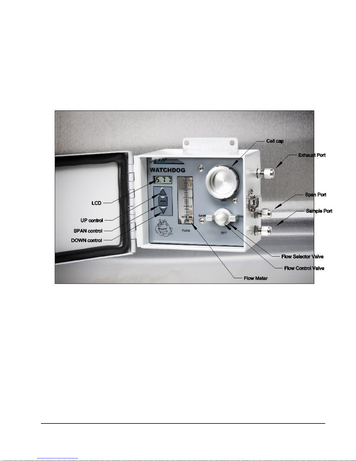
Patented Cellblock Technology: Integrates all
components such as: flow control valve, flow
meter, 3-way calibration valve,
Sample/Span/Off and compression fittings to
be an integral part of the cellblock,
eliminating tubing and fittings. The cell block
also provides a compact size, fast response
time and front panel sensor access without
the need for tools.
Area Classification: Designed to meet
requirements for Class 1, Div. 2, Groups C,D
application.
Unaffected by changes in flow rate from 0.1 to
2.0 SCFH
Wall mount or 2.0” pipe with standard pipe
clamp.
Compact size.
2 year warranty for analyzer, parts and labor.
6 month sensor warranty, life expectancy 1-2
years.
Note 1: Requires optional AMI User
Interface Software

AMI Analyzer Manual Watchdog Oxygen Analyzer
4
Oxygen sensor:
AMI manufactures its own electrochemical sensor. It measures the concentration of oxygen in a gas
stream, using an oxygen specific chemistry. It generates an output current in proportion to the amount of
oxygen present, and has zero output in the absence of oxygen, thus avoiding any requirement to zero the
analyzer. The cell is linear throughout its range. The span calibration may be performed using standard
span gases or ambient air. Unlike competitive sensors, the AMI sensor is made using a high capacity
metallic body that provides long life with about twice the active ingredients of conventional sensors, but
with much faster come-down times –typically under twenty minutes to 10ppm from a 1 minute air
exposure.
Sensor Warranty:
The sensor is warranted to operate for a period determined by its class. If the sensor ceases to operate
correctly before this time has elapsed, contact AMI for a return authorization for evaluation. If there is any
evidence of defective material or workmanship the sensor will be replaced free of charge.
NOTE: Any evidence of abuse or physical damage, such as a torn membrane, will void the warranty.
Instrument Warranty:
Any failure of material or workmanship will be repaired free of charge for a period of two years from the
original purchase (shipping date) of the instrument. AMI will also pay for one way UPS ground shipment
(back to the user).
This warranty does not cover the sensor, which is covered by its own warranty (see above).
Any indication of abuse or tampering will void the warranty.

AMI Analyzer Manual Installation and Operation
5
Installation and Operation
Receiving the analyzer
When you receive the instrument, check the package for evidence of damage and if any is found, contact
the shipper.
Do not install the sensor until the analyzer is completely installed, the gas lines are plumbed and the
electrical connections are all made; and sample or zero gas is ready to flow into it.
Installation.
This section contains important information to do with safety and installation. Please don’t skip it!
Do not open the sealed metallized T-2 or T-4 oxygen sensor bag or install the sensor until the analyzer is
completely installed, the gas lines are plumbed and the electrical connections are all made; and sample
or zero gas is ready to flow into it. If you do you will expose the sensor to so much oxygen in the air that
it will be saturated and may not come down to low levels for a very long time.
-------------------------Points to consider first! ------------------------------
Environment –what is the temperature range going to be where the analyzer will be installed? If the
temperature is going to go below freezing, you need to place it in a temperature controlled meter building.
If this is not possible, you should really be using a heated 2010BR. Also, make sure it won’t get too hot in
the summer –you may need to ventilate or even air condition a building. Use a solar panel as a sunshield if
one is to be used. The standard temperature specification is 25ºF to 115°F.
Sample conditions –if your sample is hot and wet, you will need to keep water from condensing in the
sample line or analyzer. The AMI demister brings hot and wet gases back to ambient temperature and
allows the condensation and entrained liquids to fall back into the pipeline (no draining is necessary, unlike
a coalescing filter which requires routine maintenance). The Liquid rejection probe stops occasional slugs of
water from contaminating the analyzer, and acts as a check valve, so that if a compressor goes down
drawing a vacuum on the line, air is not drawn back into the analyzer through its vent. It is available with a
built-in pressure regulator for high pressure lines (up to 1200psig).

AMI Analyzer Manual Installation and Operation
6
Power supply –if you are going to run the unit off solar power, using a battery, you need to size both the
battery and the solar panel correctly. The analyzer draws about 30mA at 14.4 volts, but if you select the 4-
20mA output option this will go up to about 60mA.
Location:
The unit is designed to be mounted on a wall or on a 2” pipe in a general purpose, Class 1 division 2 Group
C,D area. It must not be mounted outdoors unless precautions are taken to avoid exposing it to
temperature extremes or water ingress. It MUST NOT be enclosed in another sealed enclosure such as a
NEMA 4 box, as this will violate its safety design. A vented box or enclosure is acceptable. Although the unit
is RFI protected, do not to mount it close to sources of electrical interference such as large transformers,
motor start contactors, relays etc. Also avoid subjecting it to significant vibration –don’t mount it on the
side of a compressor!
Give yourself enough clearance on the right side that you will not have a hard time connecting the gas lines.
Safety Considerations:
The unit is designed for installation in either a general purpose or a Class 1 Division 2 Group B,C,D area, but
it is also designed so that a hazardous gas may be introduced into its main compartment. This gas may be
any group B,C or D gas such as natural gas.
The enclosure is vented so that it can be considered as a Class 1 Division 2 area. It MUST NOT be mounted
in a Class 1 Division 1 area, or inside another sealed box.
Flashing Display:
A flashing display indicates that the unit is measuring percent ranges. When the unit is measuring ppm
levels of oxygen its display will be steady.

AMI Analyzer Manual Short-form Installation Procedure
7
Short-form Installation Procedure
Figure 1. The Watchdog
1. Mount analyzer at a convenient eye level, not too close to the right wall.
2. Connect the analyzer ground to an 8 ft. ground rod or similar high quality ground with a minimum
16AWG wire.
3. Confirm sample pressure is less than the analyzer specification (150psig).
4. Deal with any potential condensation or liquid contamination issues.
5. Connect the sample line to the sample inlet port with ¼” ss tubing.
6. Turn the Sample/Span/Off valve to the Off position.
7. Pressurize the sample line to line pressure (between 1psig and 150psig).
8. Leak check every fitting and weld from the analyzer inlet to the sample tap.

AMI Analyzer Manual Short-form Installation Procedure
8
9. Connect vent line to outside, running slightly downhill all the way.
10. Turn the Sample/Span/Off valve to the Sample position.
11. Adjust the sample flow to approximately 1 SCFH.
12. Connect power, analog output and RS485 if desired. Run the power in one conduit, and the analog
output and RS485 in the other.
13. Power up analyzer.
14. Set up as desired with a laptop.
15. Turn the Sample/Span/Off valve to OFF.
16. Unscrew the cell cap, and install the oxygen sensor.
17. Remove the shorting tab on the sensor.
18. Optional: in the User Interface (version III) press the “NEW SENSOR” button, and record the sensor
serial number.
19. Stabilize for 45 seconds ONLY, adjust span to 20.9%.
20. IMMEDIATELY turn the Sample/Span/Off valve to SAMPLE and flow sample gas at about 1 SCFH.
21. Replace the Cell cap and tighten it down (hand tight).
22. Remove the USB connection cable.
23. Replace the access panel on the side of the analyzer.
24. Purge with sample gas for half an hour, or until the oxygen reading has fallen to low ppm levels.
25. If desired, span with known calibration gas.
Laptop set up procedure:
1. Make sure the laptop has the FTDI driver installed.
a. Windows 7 will probably find the driver by itself, but XP probably won’t.
b. Run the program called CDM20824_Setup.exe which is either in the AMI CD, or can be
downloaded from the FTDIchips.com site.
2. Install the AMI program if you haven’t done so already.
3. Run the program.
4. On the User Interface screen, at the top, click the “Port” button. Note the ports listed.
5. Make sure the analyzer is powered up, and connect the USB cable to it.
a. If you connect the cable without power to the analyzer, the port won’t appear.
6. On the User Interface screen, at the top, click the “Port” button again, and you should see an
additional port. Select this port.
7. Let the program figure out how to talk to the analyzer, and watch it load up all the boxes with
numbers or words.

AMI Analyzer Manual Short-form Installation Procedure
9
8. If you want to name the analyzer, click on the “User ID:” box. A dialog box will come up, asking for
a password. Use “AMI” as the password, and then write in up to 12 characters as a name for the
analyzer.
9. Set up the output range, that is the range used by the analog output to scale the output for your
monitoring device. People often use 100ppm in the natural gas world.
10. Make sure the security settings are the way you want them.
11. Make sure the display shows the correct output type, 1-5V or 4-20mA.
12. Go through the analog output calibration procedure if desired.
13. If you are installing the sensor, click on the New Sensor button and write in the serial number.
14. Check the analyzer date and time is correct (we set it up for Pacific Standard time, which may not
be correct for you). You can send the computer time to the analyzer by clicking the Set Analyzer
Time button.
15. Clear the stored data by clicking the “Clear Data” button in the DATALOG section on the right.

AMI Analyzer Manual Expanded Installation Procedure
10
Expanded Installation Procedure
Figure 2. The Watchdog
This section follows the format of the installation procedure above but with greatly expanded explanations
and coverage of detail issues.
1. Mount analyzer in a shelter if possible, at a convenient eye level, not too close to the right wall.
The gas connections are made on the right side of the analyzer, while the electrical connections are on the
left side. Leave enough space on the right side of the analyzer for the gas connections.
The analyzer can be mounted on a wall, or on a two inch pipe.
If the analyzer is mounted outside, make sure it has some kind of sun shade. If it is DC powered with a solar
panel, use the panel to give the analyzer shade.

AMI Analyzer Manual Expanded Installation Procedure
11
If the analyzer is mounted in a building with other equipment, make sure it won’t get too hot during the
summer. The sensor will rapidly die in temperatures higher than 115ºF. You may need to install ventilation
or even air conditioning.
Remove the access panel on the left side of the analyzer so you can make the electrical connections.
2. Connect the analyzer ground to an 8 ft. ground rod (or similar high quality ground) using at least
16AWG wire.
It is essential for safety that the analyzer has a good ground. Normally an 8ft rod pounded into the ground
will suffice, but in very dry or sandy areas something better may have to be done. Sometimes gas running
in pipelines can develop serious static charges on the lines, causing the pipeline to be at a high voltage
compared with the local ground. Be aware of this and make sure the pipeline is well grounded itself.
3. Confirm sample pressure is less than the analyzer specification (150psig). If it is higher, use a
suitable regulator such as the high pressure AMI Liquid Rejection Probe. Such a regulator must
have a stainless steel diaphragm.
The analyzer needs a minimum of about 1 PSIG, and a maximum of 150psig sample pressure. If the
pressure is too low, the gas flow will be low and the response time long, and if the flow is very low the
effect of minor leaks will become significant. If the pressure is too high the analyzer will be damaged, and
you may get a hazardous situation if the sample is flammable.
The response time will depend on the length of tubing, the diameter and the flow rate of gas through it.
You can roughly calculate it by assuming that the volume of tubing –the length multiplied by its internal
area –has to be completely replaced by the gas flowing before you get a representative reading. If the
sample pressure is high, the volume is effectively increased because more gas is packed into the tubing.
AMI can provide a version of the Liquid Rejection Probe with a built-in regulator that can handle pressures
up to 1500psig.
4. Deal with any potential condensation or liquid contamination issues.
If the sample may contain condensable liquids, they must be prevented from entering the analyzer. Natural
gas, for example, often contains water in vapor or liquid form, and other liquids such as oils, glycols or
methanol. Such liquids tend to collect in dips in the sample line, and come through the line as slugs,
particularly if the line is cleaned by “pigging” it (sending a cleaning device through it, preceded by a tidal
wave of sludge). Compressors heat the gas and also cause liquids to condense, particularly when the gas
cools off, so that even apparently dry gas going into a compressor may contain liquids coming out. AMI can
provide a “Demister” and Liquid Rejection Probe” that together work to prevent problems from hot wet
gases. The demister acts to coalesce droplets and cool the gas, while the Liquid Rejection Probe stops any
liquids from getting to the analyzer. Any liquids fall back into the pipeline, thus minimizing maintenance
issues. Also, the Liquid Rejection Probe acts to prevent the problems that arise when the source of the gas
is shut off while the downstream compressor continues to run, thus pulling a vacuum on the line. Normally
this would cause air to be drawn into the line through the analyzer vent, but the Liquid Rejection Probe
contains a very sensitive check valve that prevents this.

AMI Analyzer Manual Expanded Installation Procedure
12
5. Connect the sample line with ¼” stainless steel tubing.
Use stainless tubing only to connect the sample to the analyzer. Other materials are either not robust
enough or in the case of plastics, allow oxygen to enter the sample via diffusion. Normally ¼” tubing is
adequate unless the sample run is very long and the source pressure low –in this case you may have to use
wider tubing.
You should have some kind of blocking valve on the sample port. If you use a Demister, use at least a half
inch ball valve at its base.
6. Turn the Sample/Span/Off valve to the Off position.
The Sample/Span/Off valve is to the lower right of the grey faceplate above. This valve contains a Flow
Control (metering valve) in its center. If you turn the Sample/Span/Off valve to the off position, it will stop
either sample or span gas from flowing into the analyzer –but the exhaust is still connected to the
atmosphere so when you have a sensor in the analyzer it is not sealed off by this valve. At this point in this
procedure you shouldn’t have the sensor in place yet. Don’t use the metering valve to shut off the flow (as
it is a fine adjustment valve)!
7. Pressurize the sample line to line pressure (1 –150psig).
The exact pressure doesn’t matter – we want enough so that you can easily see leaks in the following step.
8. Leak check every fitting and weld from the analyzer inlet to the sample tap.
Use a liquid soap solution such as “Snoop™” or similar. Don’t spray it on! You are looking for little bubbles
that appear after a while, indicating a leak. Even the tiniest leak will allow oxygen to enter the gas stream,
no matter what the pressure inside the line is. Check absolutely every possible source including welds,
valve packing, and fittings both around the tube and the nut, and anything else that might leak.
Oxygen can get into the gas stream because you are dealing with diffusion of molecules, not the flow of
water. To an oxygen molecule, 3000psig of gas still has enough spaces between its molecules that it looks
like zero pressure. People often don’t understand this until Mother Nature teaches them about it the hard
way. So at this point, be absolutely sure that you don’t have any leaks.
9. Connect the vent line to outside, running slightly downhill all the way.
Particularly if the analyzer and gas is warmer than the environment, any water vapor in the gas will tend to
condense in the vent line. If the line runs uphill, or has a low point, water will collect and potentially freeze,
stopping the flow. If the sample gas is flammable, the vent must go to a safe area.
Also take precautions that insects don’t make nests in the exhaust line. You may need some sort of a grill
over it.
10. Adjust the sample flow to approximately 1 SCFH with the Flow control valve located in the middle
of the Sample/Span/Off valve.
The Flow Control Valve is the metering valve in the middle of the Sample/Span/Off valve. It is a sensitive
needle valve –so don’t try to use it to shut off the flow. Turn the main valve to the OFF position for this.

AMI Analyzer Manual Expanded Installation Procedure
13
The exact flow rate is not important –1 SCFH is half way up the flow meter, so is easy to see. You want the
flow between about 0.5 SCFH and 2 SCFH at the maximum. Lower flows will result in longer response
times, and possibly higher oxygen readings as minor leaks aren’t diluted as much by the flow. Higher flow
rates will tend to increase the pressure on the sensor which will increase the oxygen reading.
11. Leave the Sample/Span/Off valve on the analyzer pointing to SAMPLE and allow the sample gas to
purge the unit while you wire it up.
You want to get rid of all the oxygen trapped in the tubing, fittings and dead areas in the cell block. Also, at
the oxygen levels we are normally measuring we essentially have to flood the whole sample system with
enough gas to dilute the oxygen originally in the tubing enough to become insignificant. You don’t push out
one gas with another –the new gas simply dilutes the old gas in the system. Again, this is not intuitively
obvious.

AMI Analyzer Manual Expanded Installation Procedure
14
Figure 3. Electrical connections
12. Connect power, analog output and RS485 if desired. Run the power in one conduit, and the
analog output and RS485 in another. You can use flexible conduit for Class 1 Div. 2 areas. See the
NEC.
All the electrical connections are located on a single Phoenix pluggable connector behind a panel on the left
side of the analyzer. Make sure the wires are connected per the markings –Positive to +ve, return to the
ground symbol. This terminal should also be used if required for any shield connections for the output or
RS485 connections. The output connections are made on positions 3 and 4, and the RS485 connections on
5 and 6.
The analog output –which may be either 1-5V or 4-20mA –is connected to the “+” and “-“ symbols (3 and
4). This signal is isolated from ground. If the device to which you are connecting is also isolated from
ground, make sure you ground the “-“ connection at the analyzer. The terminal marked by the ground
symbol may be used for this purpose, in which case the output is no longer isolated. DO NOT GROUND

AMI Analyzer Manual Expanded Installation Procedure
15
BOTH ENDS! If you do so, you will generate a ground loop which will seriously upset the readings. Normally
you would use the ground terminal for a shield. You can select which output is in use. The voltage output is
lower power, but more prone to interference. If you decide to change it, you will probably have to perform
an output calibration, described later in this manual.
The two terminals marked A and B are for the RS-485 ModBus connection. This is not isolated from ground.
Run the power through one conduit, and the analog output and RS485 lines through the other.
Make sure you are following the NEC (National Electrical Code) when you wire it up. Also make sure you
have a way of removing power from the analyzer nearby, per the code.
13. Power up analyzer.
When you do so, the LCD should light up.
14. Turn the Sample/Span/Off valve to OFF.
15. Unscrew the cell cap, and install the oxygen sensor.
Unscrew the cap first. Open the sensor bag, remove the sensor by holding the little handle and
immediately put it into the cell compartment, gold side up, and with the little metal tag on the side facing
you. When it is in place, hold the sensor in place and pull out the tag. Do it in this order so that the sensor
is always operating, eating up oxygen that gets in through its membrane. The length of time you take over
this is critical in determining how long the sensor takes to get down to a low range.
16. Optional: in the User Interface (version III) press the “NEW SENSOR” button, and record the
sensor serial number.
You might just want to write it down. Note that you can read the serial number while the sensor is in place
in its cell block pocket –don’t leave the sensor out while you write it down.
17. Stabilize for 45 seconds ONLY, adjust span to 20.9%.
It will take the sensor about 20 seconds to come to a reasonably stable reading, but give it 45 seconds to be
sure. Don’t go over this time, even if the reading is still moving. The sensor is probably changing
temperature a bit which affects its reading until it has equilibrated with the analyzer. You aren’t concerned
with the utmost precision at this point, just a close-enough value. If you leave the sensor in air too long, it
will take much longer to come down to low oxygen levels than you expect.
18. IMMEDIATELY turn the Sample/Span/Off valve to SAMPLE.
Do this before you screw on the cell cap, because you will get rid of most of the air in the cell pocket
immediately, helping the sensor come down quickly.
19. Purge with sample gas for half an hour, or until the oxygen reading has fallen to low ppm levels

AMI Analyzer Manual Expanded Installation Procedure
16
it should drop to less than 10ppm in less than 20 minutes, if it has been installed properly, the temperature
is above 50ºF, and always assuming your sample has less than 10ppm of oxygen in it. (Cold temperatures
cause the sensor to respond more slowly).
You may be required to perform a low level span –this means spanning the analyzer with a suitable span
gas whose value is close to where the analyzer will be operating. If so, it is essential that the analyzer gets
down to a lower value than the span gas value, or it will take forever to exponentially work its way down to
the span gas reading.
Often this operation causes problems. For example, the span gas may be contaminated, or the regulator
hasn’t been properly bled. A good first step is to simply run the span gas through the analyzer and see what
it reads. If it is close to the correct value, you can go ahead and span it. If it isn’t, you MUST trouble shoot
why not before you believe the span gas! The calibration you just did on air is going to be accurate to
within about 2% of reading, probably, which is closer than many span gases!
20. If desired, span with known calibration gas.
a) Connect a regulator (with Stainless Steel diaphragm ONLY) to span gas tank.
A regulator with any other kind of diaphragm will allow oxygen to diffuse into the gas, contaminating it.
b) Bleed high pressure side of the regulator 7 times.
This effectively removes trapped oxygen from the air in the primary side of the regulator. If you just try to
purge it by flowing gas through it, it will take a very long time to get rid of all the air and you may
contaminate the gas in the bottle. Bleeding the regulator can save days of time.
c) Bleed low pressure side of the regulator 7 times.
Removes the air from the secondary side. Bleeding the regulator can take days off the stabilization time.
d) Shut off the regulator outlet valve and leak check all fittings, gauges and packing glands with
Snoopor equivalent.
Again, flow the liquid on, don’t spray it on. Make sure you check the regulator and tank valve as well.
e) Flow calibration gas preferably through a length of AMI supplied tubing WHILE you are
connecting the tubing to the span gas fitting. Allow the gas to purge around the fitting for
about 20 seconds before you tighten it.
It is preferable to use the AMI special flexible non-diffusive tubing with its O-ring sealed fittings so that you
don’t destroy the span inlet fitting on the analyzer. This can be purchased from AMI as an option.
Compression fittings can only take a few openings and closings before they cease to seal well enough for a
trace oxygen analyzer. Flow the gas through the tubing while you attach it to the span fitting: screw it on by
one thread allowing the gas to escape around it, and after about 20 seconds tighten it up. This displaces the
air from the fitting, meaning that you don’t inject a slug of air onto the sensor and delay it coming to
stability.
f) Tighten fitting on the span gas inlet.
Use Snoop™or equivalent to leak check it.

AMI Analyzer Manual Expanded Installation Procedure
17
g) Turn the analyzer Sample/Span/Off valve to the SPAN position.
You will probably see the reading shoot up for a moment as the air in the span gas port is pushed past the
sensor, then the reading will start to stabilize.
h) Allow to stabilize for 2-5 minutes.
This will allow any residual air to be flushed out and the sensor to come to equilibrium.
i) Verify that the analyzer reads within about 15% of the span gas value.
If it doesn’t, something is wrong. If the sensor reads very low, check it on air, and if that reading is also very
low, replace the sensor (you shouldn’t have to do this with a new sensor!) If the reading is too high, it is
possible that your span gas is contaminated, or you have a leak, or you have made some kind of error. One
thing to note is that if the analyzer temperature is very different from the sensor temperature when you
put it in, the reading will be quite wrong until the sensor has had a chance to equilibrate. Increase the flow
rate by doubling it, and see if the reading decreases after a few seconds. If the reading goes down with
higher flow, you certainly do have a leak. You can also time how long it takes, which will give you an
indication of where the leak is. The longer it takes for the flow change to affect the leak, the further from
the analyzer is the leak source. Fix it by using Snoop and try again.
j) If so, adjust the analyzer span until it reads the span gas value.
Press the SPAN button. The SPAN flag should appear on the LCD. Press the UP or DOWN arrow buttons
until the reading is correct. After a few seconds the SPAN flag will go out and the analyzer will accept the
new calibration.
k) Let it go back to normal operation then press the UP arrow and note the number displayed
(the “Calibration factor”).
You can use this to get an idea of the remaining cell life in the future. The analyzer also stores the
calibration values in memory so you can view the history later. When the sensor is new it will have a
Calibration factor (also called Span factor) of about 450. As it gets used up, this number will have to
increase when you span the analyzer until it gets up to around 950 or so (the Calibration factor doesn’t
increase by itself, it only does so when you span the analyzer). You will probably see the span factor remain
fairly constant, then suddenly change. When it does so it means that you will need a new sensor soon. The
sensor behaves rather like a NiCd battery –it is stable until suddenly it starts to fail.
l) Rotate the valve back to the Sample position.
The analyzer is now set up and calibrated. It is normally good practice to give it a day or two and recheck
the calibration.
Table of contents
Other AMI Analytical Instrument manuals