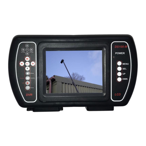
DART SYSTEMS DartEye2 User manual

2
D ARTEYE 2 –USER GUIDE
CONTENTS
Monitor Overview
The Reel
Quick Start Guide
Sonde Operation
Distance Meter Counter
Keyboard Operations
Recording
Screen Overlays & Menus
Battery
Charging/Recharging
Tips
Connecting to the WiFi
Specifications
4
5
6
6
7
7
8
8-12
13
13
13
14
15

3
The system is not earthed. If mains operated equipment is connected to the
system then the external equipment must be earthed.
Do not use the DartEye System in potentially explosive environments. This
equipment is not approved for use in hazardous environments.
Drain Cameras are heavy. Always use the wheels to aid transport. Observe
heavy lifting practices when lifting the System.
Foul water can be a source of biological hazards. Wear appropriate
protection at all times.
The camera head will get hot during use, this is normal. Take care when
handling the camera at all times.
D ARTEYE 2 –USERGUIDE

4
D ARTEYE 2 –USER GUID E
THE MONITOR
4
8
11
6
5
3
9
1.
2.
3.
4.
5.
6.
On / Off Switch
Keyboard Monitor
Controls
Recording Controls (useskeyboard) Reel
(Camera) Connector
AC Adaptor Input
7.
8.
9.
10.
11.
Video out
USB Card Slot
Battery Status Indicator
Sonde Switch –Switches Sonde off / on
Light Control
10
1
7
2&4
FIG 1

5
THE REEL
4
5
2
3
1
FIG 2
D ARTEYE 2 –USER GUID E
1.
2.
3.
4.
5.
Push rod Reel –Available in 60 or 120 Mtr Lengths
Rod Guide –Guides the rod on and off the reel
Brake –Push/Pull mechanism to lock the reel
Sonde 33 KHz
Camera 54mm Diameter Self Levelling

6
SWITCH ON
Turn the system on using the power
switch located at (fig1(1)).
BRAKE
Release the brake to allow the camera
and cable to be withdrawn from the
unit. The brake mechanism is spring
plunger. Pull and twist the plunger to
release the brake and leave the brake
in the off position.
Twist the plunger to apply the brake,
the cage will continue to rotate until the
plunger locates the next hole in the
cage wheel and secures itself.
LIGHTS
The lights on the camera head are
controlled by the rotary switch on the
D ARTEYE 2 –USER GUID E
The monitor is secured to the frame by aligning the two posts on the frame with
the underside of the monitor case and inserting the locating pin on the frame into
the securing hole on the underside of the monitor case.
Toremove the monitor from the frame, grasp the closed monitor on each side and
pull from one side, this will release the internal spring catch that secures the
monitor.
Attach the frame interconnect cable connectorto the monitor via the connector
[fig1(5)].
Check the battery level by pressing and holding Battery Status Indicator [fig1(9)],
each illuminated segment represents 20% battery life remaining.
monitor at (Fig1(11)), the unit is set up
to operate in 4 –6” pipes with the light
control set to half on. This is the
optimum set up for light output and
battery life. The screen will also “auto-
balance” itself if the light intensity is
turned up so controlling the amount of
glare seen on the screen.
SONDE
The unit is fitted with a 33Khz location
transmitter (Sonde). Toturn the Sonde
on press the Sonde button (fig1(10)),
to turn the Sonde off press the button
again. When the Sonde is operating a
green LED will be illuminated. The
image is turned off whilst the Sonde is
transmitting, due to interference
caused by the high signal strength.
7
DISTANCE COUNTER
The on-screen distance counter provides anestimate of how much rod has been
deployed, which can be used to establish the position of the camera head.
The cable counter can be reset to zero at any time to give a relative distance
count from a certain point by pressing F6 on the keyboard, the text
“Encoder 1 reset” will appear on the screen and the measurement shown at the
bottom left of the screen will now show 0.00m.
KEYBOARD OPERATIONS
D ARTEYE 2 –USER GUID E
Key Menu Item
Enter, Space Menu
F2 Menu
Escape Stop
R Record / Pause
S Snapshot (screenshot)
P Pause toggle
M Mute toggle
F Fast Forward (by an increment)
D Rewind (by an increment)
T Title overlay toggle
E Extra overlay page
AAdditional overlay page
C Coded overlay page
F6 Resets the Distance Counter

8
RECORDING
DO NOT CHANGE/EDIT PRIMARY
OVERLAY.
R
P
Esc
Press R on the keyboard to start
recording
Press P on the keyboard to
pause recording
Press Esc to stop recording
SCREEN OVERLAYS / TEXT
EDITOR
CUSTOM TEXT OVERLAYS
Insert USB in to the DartEye2 before
turning on.
TO CREATE TITLE OVERLAY
Press SPACE to enter menu, down to
overlay, then down to setup title
overlay. Press ENTER on edit text.
Type in your title and press Esc. Scroll
down to save and hit ENTER. Your title
overlay is now saved to your USB
storage device.
TO SHOW TITLE OVERLAY
Press Tto show the title overlay, and
Esc to exit edit mode. To clear the
screen press T again.
TO SHOW EXTRA OVERLAY (Eg.
ADDRESS)
Press E and a second free text page
(eg. Job address) opens allowing the
page to be edited. Once complete
press the Esc key and the page is
D ARTEYE 2 –USER GUID E
saved and will appear on the screen in
the format it has been saved in.
To clear the screen press E again.
TO SHOW ADDITIONAL OVERLAY
Same as Extra Overlay, but using the A
key instead.
TO SHOW CODES
Press C and the sentence “Enter
Code:” appears. If the code is known
this can be entered here or press the
Enter key and the list of pre-set codes
willappear.
Use the up and down arrow keys to
select the required code and press
enter. The selected code narrative will
appear on the screen. Press C again
and the text will be removed.
CL
CC
CM
FL
FC
FM
B_
H_
D_
XP
JD
OP
Crack Longitudinal
Crack Circumferential
Cracks Multiple
Fracture Longitudinal
Fracture Circumferential
Fractures Multiple
Broken Pipe
Hole in Drain/Sewer
Deformed Drain/Sewer
Collapsed Drain/Sewer
Displaced Joint
Open Joint

9
MENU OPTIONS
Tobring up the list of menu options
press the space bar or F2.
Top
menu
Play
video
View
snapshots
File management
Setup
D ARTEYE 2 –USER GUID E

10
Help with
Keys
Play video
Plays video (.mp4) recordings stored
on the media. Selecting “Play video”
brings the next menu level:
Selections are displayed if both internal
and external storage devices are
present. If only one is present, the files
list is displayed. File selection is made
using the arrow keys.
Pressing OK/Enter starts playback.
Escape or Stop terminates the
playback.
View snapshots
Displays snapshots (.jpg) recordings
stored on the media. Behaviour is
similar to “Play video”.
Copy
video from internal
D ARTEYE 2 –USER GUID E
==Play video source==
Internal
External
File management
Selecting “File management” brings
up the following selections:
Copy
Copy
Copy
Copy
video from internal
video from external
snapshots from internal
snapshots from external
Delete files from internal
Delete files from external
Some of the choices may not be
present depending
on the number of storage devices
connected.

11
NOTE: THE FOLLOWING SECTION SHOULD NOT BE CHANGED
WITHOUTFULLY UNDERSTANDING THE IMPLICATIONS.
Setup
Selecting “Setup” brings up the next
menu level:
Set Date/Time
Allows setting the battery backed-up
real-timeclock. The real-time clock is
used to automaticallygenerate file
names for saved video files and
snapshots. There is also an option of
having the date/time text overlay
present in recorded video and
snapshots.
Video
Brings up Video setup menu:
==Setup Video==
Video Standard
Allows selection between NTSC and
PAL.
D ARTEYE 2 –USER GUID E
Interpolate
Turning interpolation ON gets rid of
motion artifacts at an expense of some
vertical resolution loss.
Video Bit Rate
Determines the compression level of
recorded video. The higher the bit rate,
the higher the quality, the more space
is required on the storage device.
Playback Seek
Adjusts the amount of time
skipped when using Rewind and
Fast Forward functions.
Snapshot quality
Adjusts the compression level of
JPEG snapshots. The higher the
setting, the higher the quality and the
larger the file size.
Recording at power-on
When set to ON recording starts
automatically once the board is
powered on with approximately 20-30
second boot delay.
Audio
Brings up Audio setup menu:
==Setup Audio==
Audio Volume
Adjusts input volume. The higher the
value the louder the recorded audio is.

12
Mute Recording at Start
Selecting “On” disables audio
recording each time recording is
started. Audio recording can be
enabled and disabled while recording
is in progress by pressing the “M” key
on the keyboard, or a corresponding
key on the keypad.
Audio Input
Selects between microphone and line.
Note that available type of input
depends on the model and assembly
option of the board.
Playback Volume
Adjusts audio playback volume.
Overlays
DO NOT CHANGE PRIMARY
OVERLAY
Brings up Overlay menu:
==Overlays==
Text Display
Turns the overlay text on or off. Allows
selecting one of 2 font sizes.
Text
Brings up Select Overlay Text menu
==Select Overlay Text==
This menu allows selection of text to
be displayedon top of live and
recorded video
D ARTEYE 2 –USER GUID E
The following conventions are used:
^d –current date;
^t –current time;
^e –encoder #1 data;
^f –encoder #2 data.
Currently selected length unit (m or ft)
is displayed for each encoder.
Units are selected in Rotary Encoders
menu (see below).
Custom text
Allows entry of up to 5 custom strings
for an overlay. Only one of five is
displayed at any given time.
Date Format
Allows selection of various date
formats for date overlay.
Time Format
Allows selection of various time
formats for time overlay.
Background
Selects background transparency for
overlays.
Move...
Moves the overlay box across the
screen in selected direction.
Record Storage Device
Allows selecting device(s) that video
and snapshots are recorded to:
internal, external or both. If “Prompt”
option is selected the user is prompted
each time a recording is started.

13
POWER SUPPLY / BATTERY
CHARGER
The system is supplied with a mains power adapter. The adapter should be
plugged into and secured to the socket on the side of the monitor (fig1 (6)). The
system can be run from a mains supply or from the internal Lithium Ion Battery
Pack. When the unit
is connected to mains supply the system can be operated and the battery will be
recharged at the same time if required,
To recharge the battery only connect the power supply to the monitor whilst the
unit is turned off.
Battery charge can be identified by pressing and holding the battery status
indicator (fig1 (9)).
TIPS
Always remove debris and objects from the pipe where possible, before
inspection. The camera is designed to inspect pipes not to clear blockages.
The battery will last @ 6 hours on one charge however this will reduce if using
the WiFi function. It is advised to switch off WiFi if you do not need to use it to
conserve battery power.
It is advised to clean down the unit each day after use, this will ensure the unit
lasts longer and is also an opportunity to inspect the unit for damage etc.
D ARTEYE 2 –USER GUID E
CHANGING MEASUREMENTS FROM
METERS TO FEET
1. Press F2 to enter the menu
2. Select “Setup”
3. Select “Rotary Encoders”
4. Enter “Encoder 1”
5. Select “Units” and then choose
between meters or feet, then hit
Enter
6. Press Esc to go back to the top
level menu
7. Select “Overlays”
8. Select “Primary Overlays”
9. Select “Setup Primary Overlay”
10. Select “Custom Text”
11. Select “Custom Text 1”
12. Change the “m” for an “ft”
depending on what units you
are using, then hit Enter
13. Press Esc to clear the menu

14
CONNECTING TO THE WIFI
D ARTEYE 2 –USER GUID E
1. To use WiFi on the DartEye2 Drain Camera you will need to first download one
of the following Apps from the iPhone/Android phone Download store:-
MyTana Viewer or VLC Player
2. To turn on the WiFi setting on the DartEye2 press F2, this brings up the MENU.
3. Use the DOWN Arrow to highlight SETUP and press ENTER
4. Use the DOWN Arrow to highlight Turn WiFi ON/OFF and press ENTER.
5. The DartEye2 is now emitting a WiFi signal.
6. On your iPhone/Android phone go into your WiFi Settings and select s4011
from the list. (you may get a message saying no internet connectivity, this is normal
and should be ignored).
7. Open the relevant App and enter the following RTSP address.
rtsp://192.168.0.100:554/0 (MyTana is already setup on iPhone).
8. You are now connected to the DartEye2 through WiFi.
N.B. It is recommended that if you are not using the WiFi function the WiFi should
be disabled in the SETUP menu. This can be enabled at any time but will save
battery power if disabled when not in use.

15
SPECIFICATIONS
D ARTEYE 2 –USER GUID E
CAMERA
Exposure Control
Electronic
Lens
F3.6 (fixed)
Mode
Colour
Sensor
¼” PAL CMOS
Resolution
640 x 480
Sensitivity
<0.025 LUX
Illumination
3 x 1watt LEDs
Waterproof Capacity
IP68 to 11 bar
LCD
LCD Size
10.0inch (Diagonal)
Driver Element
TFT active matrix
Resolution
800 x 600
Display Mode
Normally White
Dot Pitch
0.264(H) x 0.264(V)
Active Area
211.2(H) x 158.4(V)
DV
Recorded File Format
MP4
Frame Rate
PAL 25 f/s
Resolution
D1:
Compression Format (Snapshot)
JPEG
Video Compression
H264 High Profile at Level 3
Working Mode
Recording/Snapshot
Memory
(Internal 64GB) (External 8GB)
SYSTEM
Power Supply
Battery Lithium 11.1V 8800maH or 15v AC Adapter
Voltage
12V DC
Power Consumption
≤1200mA
Operating Temperature
-10 to +55°C

16
Table of contents
Other DART SYSTEMS Analytical Instrument manuals