DAS AP-BLOT User manual

das
srl
Viale Tivoli Km 18,642 – 00018 Palombara Sabina (Roma) - Italy
Tel (+39) 0774 66840 – 0774 637070 - Fax 0774 634039
E- m a i l : i nf o@dasitaly c o m - h t t p : / / www dasit a l y c o m
AP
APAP
AP-
--
-BLOT
BLOTBLOT
BLOT
SERVICE MANUAL
SERVICE MANUALSERVICE MANUAL
SERVICE MANUAL
This manual contains DAS reserved information All rights reserved Unauthorized copying of this manual or parts
is prohibited

AP Blot– SERVICE MANUAL
SECTION 0
INTRODUCTION
Doc N° MDS-AP-26-00-02
Rev 01
Date: 02 04 2009
Pag 3
Ed.
Index
Indice
Date
Data
Description
Descrizione
Execution
Elaborazione
Verification
Verifica
Approval
Approvazione
0 Rev 00
29 04 08
Issue
0 Rev 01
02 04 09
General revision
Important Notes:
To avoid errors durin maintenance and repairs, carefully read the entire manual before
attemptin any work on the instrument.
Pay particular attention to the “GENERAL SAFETY WARNINGS” in Section 1 and follow instructions for specific
operations precisely as indicated in this manual


AP Blot– SERVICE MANUAL
SECTION 0
INTRODUCTION
Doc N° MDS-AP-26-00-02
Rev 01
Date: 02 04 2009
Pag 5
CONTENTS
SECTION 1 GENERAL SAFETY ............................................................................................................................. 9
1.1.
GENERAL
SAFETY
WARNINGS
AND
SYMBOLS.............................................................................. 11
1.2.
INSTRUMENT
USE
AND
CONDITIONS............................................................................................... 11
1.3.
INTENDED
USE/USERS
OF
THE
INSTRUMENT................................................................................. 11
SECTION 2 INSTALLATION AND TECHNICAL SPECIFICATIONS ........................................................... 13
2.1.
INSTALLATION ...................................................................................................................................... 15
2.2.
WORK
AREA............................................................................................................................................ 16
2.3.
TECHNICAL
SPECIFICATIONS ............................................................................................................ 16
SECTION 3 MAINTENANCE PROCEDURES .................................................................................................... 17
3.1
SYSTEM
ARCHITECTURE ........................................................................................................................ 19
3.2
REMOVING
WORK
AREA......................................................................................................................... 21
3.2.1.
REMOVING WORK AREA .................................................................................................................... 21
3.2.2.
Removing shaking plane......................................................................................................................... 23
3.3
DILUTOR
UNIT ........................................................................................................................................... 2
3.3.1.
DES RIPTION OF HOW IT WORKS ................................................................................................... 24
3.3.1.1.
Dilutor Unit......................................................................................................................................................2
3.3.1.2.
Dilutor mechanism ...........................................................................................................................................25
3.3.1.3.
Valve mechanism/Syringe................................................................................................................................25
3.3.1. .
Pump Unit ........................................................................................................................................................26
3.3.1.5.
Probe ................................................................................................................................................................27
3.3.1.6.
Probe Wash Basin ............................................................................................................................................27
3.3.1.7.
Dilutor Unit PCB Electrical Diagram...............................................................................................................28
3.3.1.8.
Dilutor unit hydraulic component diagram.......................................................................................................29
3.3.2.
REGULAR DILUTOR UNIT MAINTENAN E ...................................................................................... 30
3.3.2.1.
Visual checks ...................................................................................................................................................30
3.3.3.
SUBSTITUTING DILUTOR UNIT OMPONENTS.............................................................................. 31
3.3.3.1.
Substituting valve – syringe – dispensation probe tubing.................................................................................31
3.3.3.2.
Substituting valve mechanism..........................................................................................................................32
3.3.3.3.
Substituting 3-way Electro valve......................................................................................................................32
3.3.3. .
Substituting 3-way valve mechanism ...............................................................................................................32
3.3.3.5.
Substituting Peristaltic Pump Tubing...............................................................................................................33
3.3.3.6.
Substituting Dilutor Motor ...............................................................................................................................3
3.3.3.7.
Substituting Opto SIDILOP PCB.....................................................................................................................35
3.3.3.8.
Substituting INTERFA2 PCB ..........................................................................................................................35
3.3.3.9.
Substituting probe wash basin ..........................................................................................................................35
3. .
X–Y
AXIS ................................................................................................................................................. 36
3.4.1.
DES RIPTION OF HOW IT WORKS ................................................................................................... 36
3. .1.1.
X – Y axis movement mechanism....................................................................................................................36
3. .1.2.
X- Y axis Electrical Functions Diagram...........................................................................................................37
3.4.2.
REGULAR MAINTENAN E FOR X–Y AXIS ........................................................................................ 38
3. .2.1.
Cleaning X-Y axis tracks..................................................................................................................................38
3. .2.2.
Check belt tension ............................................................................................................................................38
3. .2.3.
Check condition of flat cables ..........................................................................................................................38
3.4.3.
ALIBRATING X–Y AXIS SETTINGS ................................................................................................... 38
3. .3.1.
X and Y axis belt tension..................................................................................................................................38
3.4.4.
Substituting X–Y AXIS PARTS ............................................................................................................... 39
3. . .1.
Substituting X-axis Movement Motor..............................................................................................................39
3. . .2.
Substituting Y-axis Movement Probe Motor.................................................................................................... 0
3. . .3.
Substituting Opto XGOLAV (X-axis movement) PCB.................................................................................... 0
3. . . .
Substituting X-axis movement belt .................................................................................................................. 1
3. . .5.
Substituting Flat Cables.................................................................................................................................... 1
3. . .6.
Substituting X-Y axis movement flat cables .................................................................................................... 1
3. . .7.
Substituting INTEROP2 PCB (Y-axis movement)........................................................................................... 2
3.5.
Z1
-
Z2
AXIS ............................................................................................................................................. 3
3.5.1.
DES RIPTION OF HOW IT WORKS ................................................................................................... 43
3.5.1.1.
Z1 - Z2 axis movement mechanism.................................................................................................................. 3
3.5.1.2.
Z axis electrical circuit diagram .......................................................................................................................
3.5.2.
REGULAR Z AXIS MAINTENAN E...................................................................................................... 45
3.5.2.1.
Z
2
axis movement control................................................................................................................................. 5
3.5.3.
Z-AXIS ALIBRATION .......................................................................................................................... 45
3.5.4.
SUBSTITUTING Z
1
and Z
2
AXIS PARTS ............................................................................................... 46
3.5. .1.
Substituting Z
1
Axis probe................................................................................................................................ 6
3.5. .2.
Substituting Z
1
Axis probe motor..................................................................................................................... 7

AP Blot– SERVICE MANUAL
SECTION 0
INTRODUCTION
Doc N° MDS-AP-26-00-02
Rev 01
Date: 02 04 2009
Pag 6
3.5. .3.
Substituting Z
2
Axis probe ............................................................................................................................... 7
3.5. . .
Substituting Z
2
Axis probe motor..................................................................................................................... 8
3.6.
SHAKING
PLANE.................................................................................................................................... 9
3.6.1.
DES RIPTION OF HOW IT WORKS ................................................................................................... 49
3.6.1.1.
Shaking plane movement mechanism .............................................................................................................. 9
3.6.1.2.
Shaking plane circuit diagram ..........................................................................................................................50
3.6.2.
MAINTENAN E AND SHAKING PLANE ALIBRATION................................................................... 51
3.6.3.
SUBSTITUTING SHAKING PLANE OMPONENTS........................................................................... 51
3.6.3.1.
Substituting Shaking Plane Motor....................................................................................................................51
3.6.3.2.
Substituting opto PCBs ....................................................................................................................................52
3.7.
CAMERA .................................................................................................................................................. 53
3.7.1.
DES RIPTION OF HOW IT WORKS ................................................................................................... 53
3.7.2.
AMERA MAINTENAN E .................................................................................................................... 54
3.7.2.1.
Checking USB cable connection ......................................................................................................................5
3.7.2.2.
Cleaning lens....................................................................................................................................................5
3.7.3.
ALIBRATE AMERA........................................................................................................................... 54
3.7.4.
SUBSTITUTING AMERA AND/OR PARTS ........................................................................................ 54
3.7. .1.
Substituting camera ..........................................................................................................................................5
3.7. .2.
Substituting camera lens...................................................................................................................................55
3.7. .3.
Substituting camera USB cable ........................................................................................................................55
3.7. . .
Substituting LED light bar................................................................................................................................55
3.8.
OPTICAL
SENSORS ................................................................................................................................ 56
3.8.1.
DES RIPTION OF HOW OPTI AL SENSORS FUN TION ............................................................... 56
3.8.2.
REGULAR MAINTENAN E .................................................................................................................. 56
3.8.2.1.
Cleaning opto ...................................................................................................................................................56
3.8.2.2.
Checking procedure..........................................................................................................................................56
3.8.3.
HE KING DISTAN E FOR OPTO OUPLERS (X AXIS) ................................................................ 57
3.8.4.
HE KING DISTAN E FOR OPTO OUPLERS (Y AXIS) ................................................................ 58
3.9.
USB
COMMUNICATION ........................................................................................................................ 59
3.9.1.
DES RIPTION OF HOW IT WORKS ................................................................................................... 59
3.9.2.
HE K FUN TIONALITY ................................................................................................................... 59
3.9.3.
REPLA ING DILAP21 and SIR4MOT P Bs ........................................................................................ 60
3.10.
DILUTOR
COMMAND
LIST................................................................................................................... 61
3.11.
HYDRAULIC
CIRCUIT
DIAGRAM ....................................................................................................... 66
3.11.1.
REGULAR MAINTENAN E .............................................................................................................. 67
3.11.2.
SUBSTITUTING HYDRAULI IR UIT OMPONENTS............................................................... 67
3.11.2.1.
Electro-valve substitution.................................................................................................................................67
3.12.
SUMMARY
OF
REGULAR
MAINTENANCE ....................................................................................... 68
3.12.1.
DILUTOR UNIT ................................................................................................................................. 68
3.12.2.
X–Y AXIS ............................................................................................................................................ 68
3.12.3.
Z2 AXIS............................................................................................................................................... 68
3.12.4.
SHAKING PLANE .............................................................................................................................. 68
3.12.5.
AMERA ............................................................................................................................................ 68
3.12.6.
OPTI AL SENSOR............................................................................................................................. 68
3.12.7.
HYDRAULI IR UIT...................................................................................................................... 68
SECTION 4 CALIBRATION PROCEDURES (XCALIB) ................................................................................... 69
.1.
INSTALLING
SOFTWARE ..................................................................................................................... 71
.2.
OPERATING
MENU ................................................................................................................................ 72
.3.
DESCRIPTION
OF
MENU
FUNCTIONS ................................................................................................ 73
. .
INSTRUMENT
BAR................................................................................................................................. 7
.5.
SETTINGS ................................................................................................................................................ 75
4.5.1.
HARDWARE ONFIGURATION .......................................................................................................... 75
4.5.2.
Language................................................................................................................................................ 76
4.5.3.
ommunication port............................................................................................................................... 76
4.5.4.
Serial number ......................................................................................................................................... 77
.6.
WORK
AREA............................................................................................................................................ 78
.7.
MAIN
FUNCTIONS.................................................................................................................................. 79
4.7.1.
Tank level Sensors.................................................................................................................................. 79
4.7.2.
Dispensation Test ................................................................................................................................... 79
4.7.3.
Dilution Test........................................................................................................................................... 79
4.7.4.
Movement Test........................................................................................................................................ 80
4.7.5.
Print Preview.......................................................................................................................................... 82
4.7.6.
Print........................................................................................................................................................ 82
4.7.7.
Turn Light On......................................................................................................................................... 83
4.7.8.
lose Function ....................................................................................................................................... 83

AP Blot– SERVICE MANUAL
SECTION 0
INTRODUCTION
Doc N° MDS-AP-26-00-02
Rev 01
Date: 02 04 2009
Pag 7
4.7.9.
Exit ......................................................................................................................................................... 83
.8.
DILUTOR.................................................................................................................................................. 8
4.8.1.
alibrate probe positions....................................................................................................................... 84
4.8.2.
alibrate probe height ........................................................................................................................... 89
4.8.3.
alibrate LT ........................................................................................................................................... 91
4.8.4.
alibrate shaking plane ......................................................................................................................... 93
4.8.5.
alibrate syringe.................................................................................................................................... 95
4.8.6.
alibrate SUL ........................................................................................................................................ 98
4.8.7.
Wash basin test....................................................................................................................................... 99
4.8.8.
Prime .................................................................................................................................................... 101
4.8.9.
alibrate camera.................................................................................................................................. 102
4.8.10.
alibrate parameters........................................................................................................................ 104
4.8.11.
Home................................................................................................................................................. 105
4.8.12.
Turning motors off ............................................................................................................................ 105
4.8.13.
Reset.................................................................................................................................................. 105
.9.
? ............................................................................................................................................................... 106
4.9.1.
Instrument information......................................................................................................................... 106
4.9.2.
Software component information ......................................................................................................... 107
4.9.3.
About .................................................................................................................................................... 107
SECTION TROUBLE SHOOTING ................................................................................................................... 109
5.1
DILUTION
/
DISPENSATION................................................................................................................... 111
5.2
X
-
Y
-
Z
MOVEMENTS............................................................................................................................. 112
5.3
CAMERA.................................................................................................................................................... 112
SECTION 6 SCHEMATIC DIAGRAMS.............................................................................................................. 113


AP Blot– SERVICE MANUAL
SECTION 1
GENERAL SAFETY
Doc N° MDS-AP-26-00-02
Rev 01
Date: 02 04 2009
Pag 9
SECTION 1
GENERAL SAFETY

AP Blot – SERVICE MANUAL
SECTION 1
GENERAL SAFETY WARNINGS
Doc N° MDS-AP-26-00-02
Rev 01
Date: 02 04 2009
Pag 11
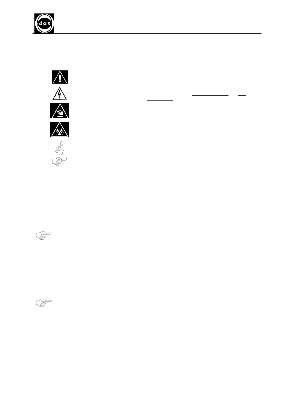
1.1. GENERAL SAFETY WARNINGS AND SYMBOLS
In this manual the following symbols stand for danger or warnings:
General DANGER symbol which indicates that a serious safety risk can occur if
instructions and warnings are not followed
Indicates ELECTRICAL VOLTAGE which could cause death upon contact Covers
with this symbol can only be removed and replaced by qualified personnel and only
after electrical power has been disconnected
Indicates that the instrument uses reagents and corrosive, irritating or noxious
DANGEROUS CHEMICAL SUBSTANCES which could damage health
Indicates that the instrument deals with potentially infectious samples (e g body
fluids such as urine) which could cause INFECTION/CONTAMINATION Always
observe general safety precautions when any of these biological substances are
present
Indicates that not following the correct instructions could damage instrument and/or
its proper functioning
Indicates that important information concerning the instrument or a Section of the
document should be read carefully
1.2. INSTRUMENT USE AND CONDITIONS
The instrument is intended for use in the following working conditions:
− as In Vitro Diagnostic (IVD) medical device as specified in the technical data
− with chemical reagents and accessories supplied and/or declared compatible with instrument
− at a specific temperature and humidity levels as specified in this manual
− not to be used and powered in a potentially explosive or fire hazardous environment
This instrument should only be used as described in this manual
Any other use has to be regarded as improper
1.3. INTENDED USE/USERS OF THE INSTRUMENT
The instrument should only be used for the intended purpose and in perfect technical conditions, only by
qualified personnel following strict safety procedures and regulations for accident prevention
This manual contains instructions for qualified personnel:
− Only Qualified Technicians are entitled to service and repair the instrument with original spare
parts and after appropriate training
Modifications of the instrument are not allowed. The user is liable for any improper
modifications and any subsequent consequences.
For extraordinary maintenance - request Specialized Technicians with authorised equipment and
original spare parts from authorised service centers


AP Blot – SERVICE MANUAL
SECTION 2
INSTALLATION AND TECHNICAL SPECIFICATIONS
Doc N° MDS-AP-26-00-02
Rev 01
Date: 02 04 2009
Pag 13
SECTION 2
INSTALLATION AND TECHNICAL SPECIFICATIONS

AP Blot – SERVICE MANUAL
SECTION 2
INSTALLATION AND TECHNICAL SPECIFICATIONS
Doc N° MDS-AP-26-00-02
Rev 01
Date: 02 04 2009
Pag 15
2.1. INSTALLATION
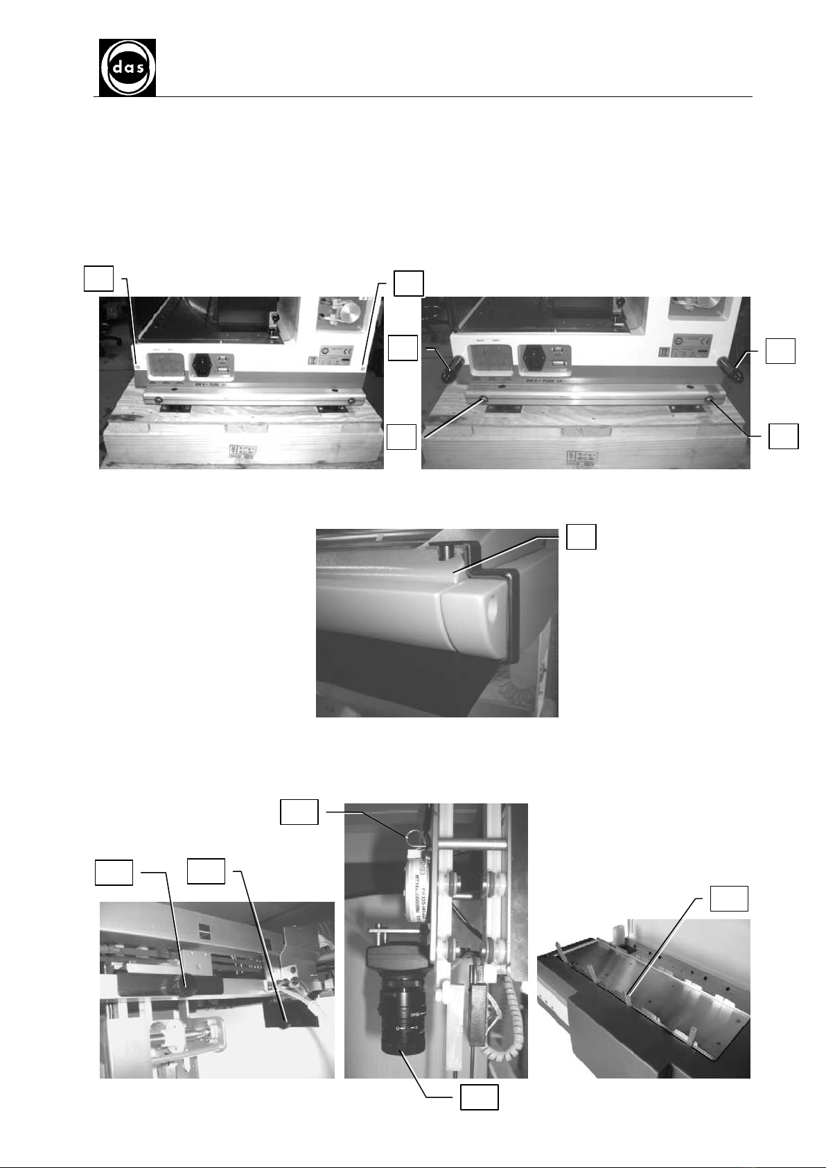
The instrument is packed with a wooden box To unpack the instrument follow the instructions described below:
a) Remove the 2 plastic covers (1-2) from the instrument right side and the other ones from the left side Screw
in the 4 handles on both sides (3-4) for manual instrument placement Once in position remove the handles e
put back in place the plastic covers
b) Remove the 4 screws that hold the instrument on to the wood base (5-6)
c) Remove screw and bracket (7), screw in the same place using the screw removed before
d) Remove, - screw and bracket (7), screw in the same place the enclosed screw in the bag
e) Remove screws (8,9,10) and related brackets
f) Remove the Z block holder (11) as indicated
g) Remove the protection cap from the camera (12)
h) Remove the blocking tools (13) from the oscillating plane
7
10
8
12
9
11
2
3
4
5
6
1

AP Blot – SERVICE MANUAL
SECTION 2
INSTALLATION AND TECHNICAL SPECIFICATIONS
Doc N° MDS-AP-26-00-02
Rev 01
Date: 02 04 2009
Pag 16
2.2. WORK AREA
AP-Blot work area showing the various components:
Probe washing
basin 48 position Sample rack Reagent and control rack Tanks
Camera Calibration area Strip holder rack
Fig 1 - AP-Blot Work Area
2.3. TECHNICAL SPECIFICATIONS
Sample rack 48 sample tubes (Ø 13mm)
Reagent rack 6 x 100ml vials and 8 control positions
Liquid Containers 2 tanks for wash buffer and waste Both with liquid level sensors
Strip Holders 6 slides (8 strips per slide) to process up to strips on oscillating plane
Dispensation System 1 dispensation and 1 aspiration probe
Strip Washing Liquid dispensation and aspiration via two instrument probes
Image acquisition system High Resolution Colour Camera (3 3 Megapixels) mounted above Probes
Dispensation Up to 2500 µl with a 1 µl resolution
Software Windows 2000 and XP compatible to set up work list, reports and result archive
Loading work lists and transmit results via Host Computer interface (LIS)
Minimum C Requirements − 200 MB free hard disk space
− CD-Rom reader
− RAM 512 MB
− Pentium 4
− Standard video card:VGA 1024x768 16 million colours
− Free USB 2 0 port
ower Requirements 230/115 VAC, 50-60Hz, 150W
Optional Bar Code Reader (BCR) for samples with position ID
Measurements 79 x 61 x 65 h (in cm)
Weight 71 Kg

AP Blot - SERVICE MANUAL
SECTION 3
MAINTENANCE PROCEDURES
Doc N° MDS-AP-26-00-02
Rev 01
Date: 02 04 2009
Page 17
SECTION 3
MAINTENANCE PROCEDURES

AP Blot - SERVICE MANUAL
SECTION 3
MAINTENANCE PROCEDURES
Doc N° MDS-AP-26-00-02
Rev 01
Date: 02 04 2009
Page 19
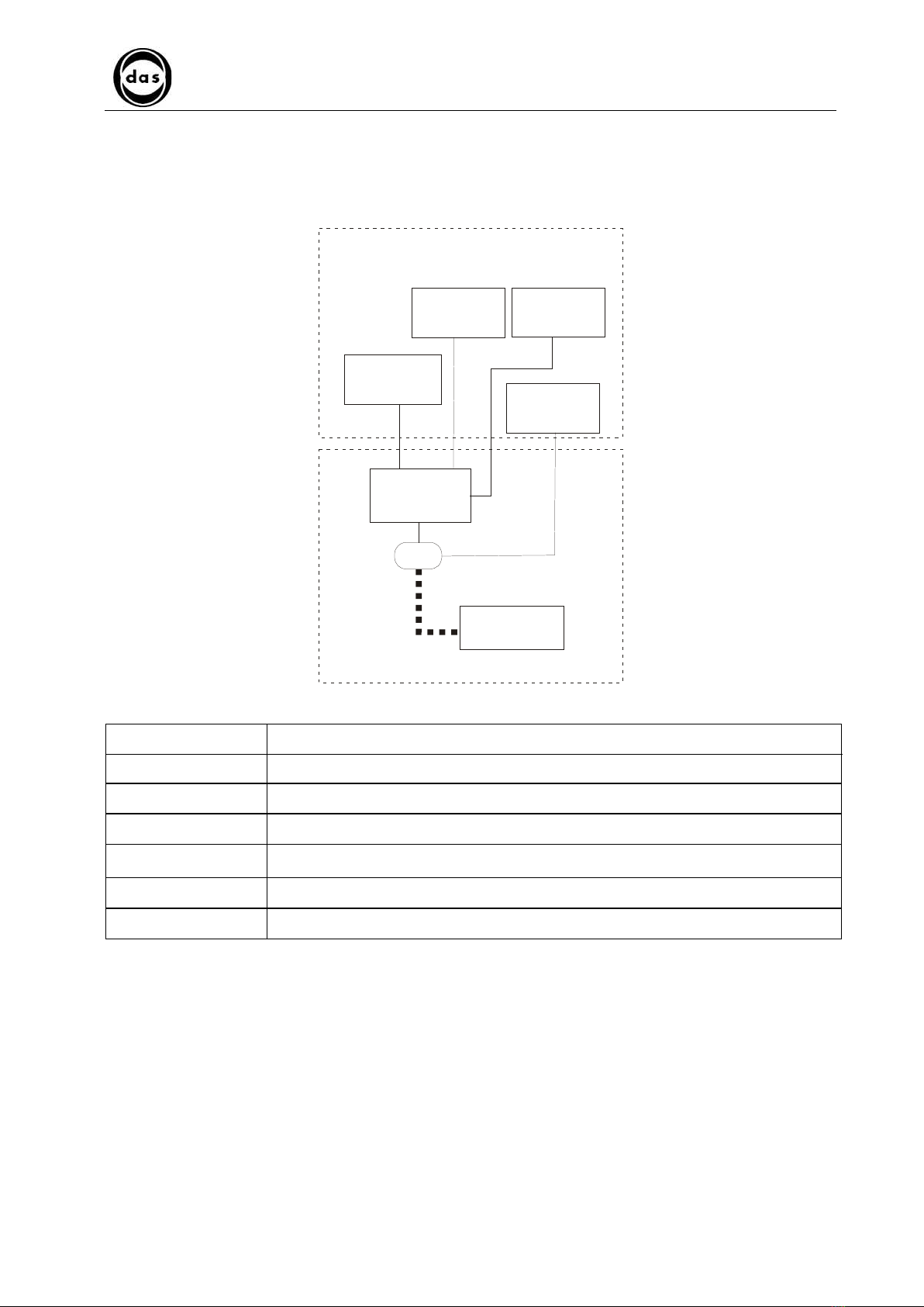
3.1 SYSTEM ARCHITECTURE
The system architecture is illustrated in the following diagram and described in table below:
Control and check board
Function group
Z1, Z2 AXIS
DIL P21
X-Y AXIS
Personal
Computer
USB
DILUTOR
UNIT
SHAKING PLANE
CAMERA
Functional unit Description
X – Y Axis The X-Y axis movement mechanism moves probe arms over work area with precision
Z
1
Axis The Z
1
axis raises and lowers dispensing probe over work area
Z
2
Axis The Z
2
axis raises and lowers aspiration probe over work area
Dilutor unit The dilutor unit aspirates and dispenses samples, calibrators, controls, and generally all
reagents It also washes Z1 axis probe internally and externally
Shaking Plane The shaking plane shakes the 6 slides holding the strips to be processed
Camera The camera acquires the images of the processed strips

AP Blot - SERVICE MANUAL
SECTION 3
MAINTENANCE PROCEDURES
Doc N° MDS-AP-26-00-02
Rev 01
Date: 02 04 2009
Page 20
The AP Blot communicates with the PC via a serial connection: between the Dilutor PCB and the PC
The units controlled by the PCB are:
PCB Unit
X – Y Axis
Z
1
– Z
2
Axis
Dilutor unit
DILA 21
Shaking plane
Table of contents
Popular Laboratory Equipment manuals by other brands

Dosmatic
Dosmatic Superdos 45 0.3% PAA operating manual

Velp Scientifica
Velp Scientifica AREC.T instruction manual

Endress+Hauser
Endress+Hauser Analytik Jena CyBio SELMA user manual

Endress+Hauser
Endress+Hauser asp-port d 2 Installation and operating instructions

IKA
IKA C 7010 operating instructions

Thermo Scientific
Thermo Scientific FT 6060 operating instructions

NPI
NPI ISO-STIM 01B Operating instructions and system description

Tuttnauer
Tuttnauer 2340E Operation & maintenance manual

Fisher Scientific
Fisher Scientific Finnpipette II Instructions for use

Rosemount
Rosemount 700XA quick start guide

InfiRay
InfiRay MH25 user manual

Thermo Scientific
Thermo Scientific 2115 Series operating manual


