manuals.online logo
Brands
  1. Home
  2. •
  3. Brands
  4. •
  5. Datalogic
  6. •
  7. Accessories
  8. •
  9. Datalogic S62 Series User manual

Datalogic S62 Series User manual

S62 SERIES
INSTRUCTION MANUAL
CONTROLS
OUTPUT LED (yellow) (S62..A/B/C/F)
The yellow LED ON indicates the output status.
STABILITY LED (green) (S62..A/B/C/F)
The green LED permantely ON indicates a stable operating
condition, where the signal received has a safety margin
higher than 30% respect to the output switching value.
The sensor is ready to function correctly.
POWER ON LED (green) (S62..G)
The green LED ON indicates the powering status and the laser
emission presence.
SENSIBILITY TRIMMER (ADJ.) (S62..A/B/C/F)
A mono-turn trimmer adjusts the sensitivity and the sensor
operating distance.
Please refer to “SETTING” paragraph for the correct use
procedure.
DARK/LIGHT TRIMMER (S62..RX/PN)
The LIGHT/DARK mode is selected using a mono-turn
trimmer.
LIGHT MODE: clockwise rotation
DARK MODE: counter-clockwise rotation.
WARNING: the maximum mechanical rotation range of the
trimmer is 240°. Do not force over of the maximum and
minimum positions.CONNECTIONS
DC models:
S62-PA-2/5-PN
S62-PA-2/5-PP/NN S62-2/5-G
AC models:
S62-PA-1-A/B/C/F S62-PA-1-G
TECHNICAL DATA
S62-PA-2/5 S62-PA-1
Power supply: 10 … 30 VDC– Class 2 (UL508) 24…240 VAC / 24…60 VDC
Ripple: 2 Vpp max. 10 % max
Current consumption
(output current excluded): < 30 mA < 3 VA
Outputs:
S62..PP/NN: PNP or NPN N.A./N.C.
30 VDC
S62..PN: NPN/PNP; 30 VDC max
(short-circuit protection)
Electromechanical SPDT
250 VAC / 30 VDC
Output current: 100 mA max
(overload and overvoltage protection)
2 A max.
(resistive load)
Output saturation voltage: 2 V -
Response time: S62…A/B/C: 500 s max.
S62…F/G: 1 ms 25 ms
Switching frequency: S62…A/B/C: 1 kHz
S62…F/G: 500Hz 20Hz
Emission type: RED (640 nm) (S62..A/B/C/G)
Operating distance (typical values): S62...B: 0.1…8 m on R2 (Ø63 mm reflector) (EG = 2)
S62…A: 13m on R2 (Ø63 mm reflector) (EG = 2)
S62...C01: 90 cm on 90% White target (EG = 2)
S62...C11: 200 cm on 90% White target (EG = 2)
S62…F/G: 0…25 m
Indicators: S62…A/B/C/F: OUTPUT LED (YELLOW) / STABILITY LED (GREEN)
S62…G: POWER ON LED (GREEN)
Adjustment: Mono-turn sensitivity adjustment trimmer
Mono-turn light/dark trimmer (S62..RX/PN)
Operating temperature: -10 … 55 °C
Storage temperature: -20 … 70 °C
Dielectric strength: 500 VAC, 1 min between electronics and housing
Insulating resistance: > 20 M, 500 VDC between electronics and housing
Ambient light rejection: according to EN 60947-5-2
Vibrations: 0.5 mm amplitude, 10 … 55 Hz frequency, for every axis (EN60068-2-6)
Shock resistance: 11 ms (30 G) 6 shock for every axis (EN60068-2-27)
Housing material: ABS
Lens material: PMMA window, policarbonate lens
Mechanical protection: IP67
Connections: 2 m cable 4 mm / M12 4-pole connector 2 m cable 5 mm
UL requirements:
VDC models: they are intended to be connected to a Class 2 transformer or class
2 power supply. VAC models: these devices shall be connected to a power-
supply or system,including filters or air-gaps, of overvoltage category II
(“load level – secondary circuit of a protected utility transformer”), suitable to
control over-voltages at the maximum “rated impulse withstand voltage peak of
1.2KV and with a short-circuit power limit at max 500VA.
Weight: 90 g. max. cable versions / 40 g. max. connectors versions
SETTINGS
S62..A/B setting: Position the sensor and reflector on opposite sides. Turn the sensitivity trimmer to maximum.
Find the points where the yellow LED (OUT) in both vertical and horizontal positions and fix the sensor in the centre
between these points. Optimum operation is obtained when both LEDs switch ON. If necessary, reduce sensitivity using the
trimmer, in order to detect very small targets. In order to improve alignment, repeat the procedure detailed above whilst
progressively reducing the sensitivity.
S62..C setting: Position the sensor and turn the sensitivity trimmer at minimum: the yellow LED is OFF
(litgh mode). Place the target opposite the sensor. Turn the sensitivity trimmer clockwise until the yellow LED
turns ON (Target detected state, pos.A). Remove the target, the yellow LED turns OFF.
Turn the trimmer clockwise until the yellow LED turns ON (Background detected state, pos.B).
The trimmer reaches maximum if the background is not detected. Turn the trimmer in intermediate position C,
between the two positions A and B. The green LED must be ON.
S62…F/G setting: Position the sensors on opposite sides. Turn the sensitivity trimmer to maximum. Find the points where
the yellow LED (OUT) is switched ON and OFF in both vertical and horizontal positions, and fix the sensor in the centre
between these points. Optimum operation is obtained when both LEDs switch ON.
If necessary, reduce sensitivity using the trimmer, in order to detect very small targets.
In order to improve alignment, repeat the procedure detailed above whilst progressively reducing the sensitivity.
DIMENSIONS
INSTALLATION
The sensor can be positioned by
means of the two housing holes
using two screws (M4x35 or longer,
1.2Nm maximum tightening
torque).
Various orientable fixing brackets to
ease the sensor positioning are
available (please refer to the accessories listed in the general
catalogue). The operating distance is measured from the front
surface of the sensor optics. The M12 connector can be oriented
at two different positions using the specific fastening spring and
rotating the block of 180°.
TEST FUNCTION (S62...G)
The TEST+ and TEST- inputs can be used to switch off the
emitter light and verify that the system is correctly operating: the
receiver output should switch when the test is activated while the
beam is uninterrupted: the inputs activating voltage range is
12…30 VDC, respecting the polarity.
The emission is switched OFF connecting TEST+ to VDC and
TEST- to 0V.
The sensors are NOT safety devices, and so MUST NOT be used in the
safety control of the machines where installed.
Datalogic S.r.l.
Via S. Vitalino 13 - 40012 Calderara di Reno - Italy
Tel: +39 051 3147011 - Fax: +39 051 3147205 - www.datalogic.com
Helpful links at www.datalogic.com: Contact Us, Terms and Conditions,
Support.
The warranty period for this product is 36 months. See General Terms and
Conditions of Sales for further details.
Under current Italian and European laws, Datalogic is not obliged to
take care of product disposal at the end of its life. Datalogic
recommends disposing of the product in compliance with local laws or
contacting authorised waste collection centres.
© 2007 - 2017 Datalogic S.p.A. and/or its affiliates ALL RIGHTS
RESERVED. Without limiting the rights under copyright, no part of this
documentation may be reproduced, stored in or introduced into a retrieval
system, or transmitted in any form or by any means, or for any purpose,
without the express written permission of Datalogic S.p.A. and/or its affiliates.
Datalogic and the Datalogic logo are registered trademarks of Datalogic
S.p.A. in many countries, including the U.S.A. and the E.U. All other
trademarks and brands are property of their respective owners. Datalogic
reserves the right to make modifications and improvements without prior
notification.
821002352 Rev. C
MIN MAX
A
B
C
RELAY
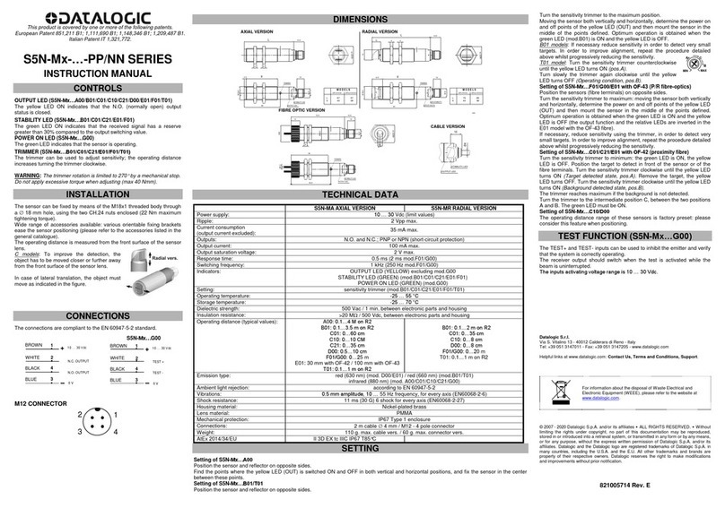
S62-PL…B Laser
Polarised retroreflex
S62-PL…C Laser
Diffuse proximity
INSTRUCTION MANUAL
S62..B S62..C
CONTROLS
OUTPUT LED (yellow)
The yellow LED ON indicates the following output status: N.O.
closed and N.C. open.
POWER ON LED (green)
The green LED ON indicates the sensor powering status and
laser emission presence.
SENSITIVITY TRIMMER (ADJ.)
Monoturn trimmer that adjusts the sensitivity and thus the
sensor operating distance.
Please refer to “SETTING” paragraph for the correct use
procedure.
WARNING: the maximum mechanical trimmer rotation is
equal to 240°. Do not apply excessive torque over the
maximum and minimum positions.
INSTALLATION
The sensor can be positioned by
means of the three housing’s
holes using two screws (M4x25
or longer, 1.5 Nm maximum
tightening torque) with washers.
Various orientable fixing brackets
to ease the sensor positioning
are available (please refer to the accessories listed in the
general catalogue).The operating distance is measured from
the front surface of the sensor optics.
The M12 connector can be oriented at two different positions
using the specific fastening spring and rotating the block to
180°.
CONNECTIONS
M12 connector
TECHNICAL DATA
S62..B S62..C
Power supply: 10 … 30 Vcc
Ripple: 2 Vpp max.
Consumption
(output current excluded): 30 mA max
Outputs: PNP or NPN N.O. / N.C.; 30 Vdc max. (short-circuit protection)
Output current: 100 mA max (overload and overvoltage protection)
Output saturation voltage: 2 V
Response time: 200 s
Switching frequency: 2.5 kHz
Emission type: RED LASER Class 1
EN 60825-1 (2014) RED LASER (= 645…665 nm): Class 2 EN 60825-1 (2014)
Class II CDRH 21 CFR PART 1040.10Pulsed emission: pot.
max 5 mW; pulse duration = 5s; frequency max = 32 KHz
Operating distance (typical values): refer to TAB.1 1m on 90% white target (EG2)
Min. detectable object dimension: 0.5 mm at 0.5m (minimum spot)
Indicators: OUTPUT LED (YELLOW) / POWER ON LED (GREEN)
Setting: Monoturn sensitivity adjustment trimmer
Functioning temperature: -10 … 55 °C
Storage temperature: -20 … 70 °C
Dielectric strength: 500 Vac 1 min., between electronics and housing
Insulating resistance: >20 M500 Vdc, between electronics and housing
Ambient light rejection: according to EN 60947-5-2
Vibrations: 0.5 mm amplitude, 10 … 55 Hz frequency, for every axis (EN60068-2-6)
Shock resistance: 11 ms (30 G) 6 shock for every axis (EN60068-2-27)
Housing material: ABS
Lens material: PMMA window, polycarbonate lenses
Mechanical protection: IP67
Connections: M12 4-pole connector
Weight: 40 g. max.
S62…B SETTING
S62…B alignment:
- Position the sensor and reflector aligned on opposite sides at the desired distance.
- Turn to maximum the sensitivity adjustment trimmer (ADJ.) (clockwise).
- Determine the powering on and powering off points of the yellow LED (OUT) by moving
vertically and horizontally the sensor and mount the
sensor in the middle of the points found.
Control:
- Enter laterally the object inside the operating
field and control that the yellow LED turns on.
- Remove the object and check that the yellow
LED turns off immediately
S62…C setting:
Position the sensor and turn the sensitivity trimmer at minimum: the yellow LED is OFF. Place the target opposite
the sensor.
Turn the sensitivity trimmer clockwise until the yellow LED turns ON (Target detected state, pos.A).
Remove the target, the yellow LED turns OFF. Turn the trimmer clockwise until the yellow LED turns ON (Background detected
state, pos.B). The trimmer reaches maximum if the background is not detected.
Turn the trimmer in intermediate position C, between the two positions A and B. The green LED must be ON.
S62…B PERFORMANCES
TAB.1: Operating distances (m)
REFLECTOR (mm)
R1 (Ø31) R2 (Ø63) R6 (60x40) R7 (51X51)/
R20 (Ø63) R8
(19X10)
0.3 … 16 0.3 … 20 0.4 … 22 0.3 … 22 0.2 … 2
Note: The use of the RT 3970 reflecting tape is not suggested.
DIMENSIONS
18x45°
50
42
11
SENSITIVITY TRIMMER
10.7 POWER ON LED
OUTPUT LED
25
6.18 mm
614 Ø15
16
M12
42
1.1
50
20.75
18
4.7
21.5 8.5
RECEIVER
EMITTER
SAFETY PRECAUTIONS
All the electric and mechanical safety regulations have to be
respected during sensor functioning.
The sensor has to be protected against mechanical damage.
Apply the labels supplied in a visible position near the laser
emission beam.
S62..C:
Do not stare directly into the laser beam!
Do not point the laser beam towards people!
Eye irradiation superior to 0.25 seconds is dangerous.
Please refer to the Class 2 Standard (EN60825-1).
These sensors can not be used for safety applications!
The sensors are NOT safety devices, and so MUST NOT be used
in the safety control of the machines where installed.
Datalogic S.r.l.
Via S. Vitalino 13 - 40012 Calderara di Reno - Italy
Tel: +39 051 3147011 - Fax: +39 051 3147205 - www.datalogic.com
Helpful links at www.datalogic.com: Contact Us, Terms and Conditions,
Support.
The warranty period for this product is 36 months. See GeneralTerms and
Conditions of Sales for further details.
Under current Italian and European laws, Datalogic is not obliged to take
care of product disposal at the end of its life. Datalogic recommends
disposing of the product in compliance with local laws or contacting
authorised waste collection centres.
© 2008 - 2017 Datalogic S.p.A. and/or its affiliates ALL RIGHTS
RESERVED. Without limiting the rights under copyright, no part of this
documentation may be reproduced, stored in or introduced into a retrieval
system, or transmitted in any form or by any means, or for any purpose,
without the express written permission of Datalogic S.p.A. and/or its affiliates.
Datalogic and the Datalogic logo are registered trademarks of Datalogic S.p.A.
in many countries, including the U.S.A. and the E.U. All other trademarks and
brands are property of their respective owners. Datalogic reserves the right to
make modifications and improvements without prior notification.
826003257 Rev. H
spot diameter (mm)
distance (mm)
MIN MAX
A
B
C
CLASS 1 EN 60825-1
(2014)
LASER PRODUCT
CLASS 2 EN 60825-1
(2014)
LASER PRODUCT
S62-PL…M Laser
Background suppression
INSTRUCTION MANUAL
CONTROLS
OUTPUT LED (yellow)
The yellow LED ON indicates the output status: N.O. closed and N.C. open.
POWER ON LED (green)
The green LED ON indicates the sensor powering status and laser emission
presence.
DISTANCE ADJUSTMENT TRIMMER (ADJ.)
The multiturn trimmer with clutch (6 turn) adjusts the suppression distance
through the mechanical variation of the optic triangulation angle.
The operating distance increases rotation the trimmer shaft in a clockwise
direction.
Please refer to “SETTING” paragraph for the correct use procedure.
POSITION INDICATOR
This indicator has a scale numbered from 1 to 6 that allows the precise
adjustment of the suppression distance on the entire operating range.
Please refer to “SETTING” paragraph for the correct use procedure.
INSTALLATION
The sensor can be positioned by means
of the three housing’s holes using two
screws (M4x25 or longer, 1.5 Nm
maximum tightening torque) with
washers.
Various orientable fixing brackets to
ease the sensor positioning are
available (please refer to the
accessories listed in the general
catalogue).
The operating distance is measured from the front surface of the sensor
optics.
The M12 connector can be oriented at two different positions using the
specific fastening spring and rotating the block to 180°.
CONNECTIONS
M12 connector
TECHNICAL DATA
S62-PL-M01… S62-PL-M11…
Power supply: 10 … 30 VDC
Ripple: 2 Vpp max.
Consumption
(output current excluded): 30 mA max
Outputs: PNP or NPN N.O. / N.C.; 30 VDC max. (short-circuit protection)
Output current: 100 mA (overload and overvoltage protection)
Output saturation voltage: 2 V
Response time: 140 s 200 s
Switching frequency: 3.5 kHz 2.5 kHz
Emission type: RED LASER (= 645…665nm): Class 1 EN 60825-1 (2014), Class II CDRH 21 CFR PART 1040.10
Pulsed emission: pot. max 5mW; pulse duration = 5s; frequency = 14KHz (mod. M01) / 10KHz (mod. M11)
Focalisation point : 60 mm 150 mm
Spot dimension: < 0.2 mm (at 60 mm) < 0.4 mm (at 150 mm)
Operating distance (typical values): 30…150 mm 50…350 mm
Adjustment: 4-turn distance adjustment trimmer 6-turn distance adjustment trimmer
Difference (90% white/ 4% black): < 4 % (see DETECTION DIAGRAM)
Hysteresis (90% white): < 1 %
Indicators: OUTPUT LED (YELLOW) / POWER ON LED (GREEN)
Functioning temperature: -10 … 55 °C
Storage temperature: -20 … 70 °C
Dielectric strength: 500 Vac 1 min., between electronics and housing
Insulating resistance: >20 M500 Vdc, between electronics and housing
Ambient light rejection: According to EN 60947-5-2
Vibrations: 0.5 mm amplitude, 10 … 55 Hz frequency, for each axis (EN60068-2-6)
Shock resistance: 11 ms (30 G) 6 shock for each axis (EN60068-2-27)
Housing material: ABS
Lens material: PMMA window; PC lens
Mechanical protection: IP67
Connections: M12 4-pole connector
Weight: 40 g. max.
SETTING
Suppression distance setting
1.Object detection
Position object to detect in front of the sensor at the distance required.
Turn distance adjustment trimmer (ADJ) to minimum: yellow LED OFF and
green LED ON.
Rotate trimmer in a clockwise direction until the yellow LED and green LED
turn ON. Object detection condition (A status of position indicator).
A
2.Background suppression
Remove object and ensure that the background is in front of the sensor:
yellow LED OFF and green LED ON.
Rotate trimmer in a clockwise direction until the yellow LED and green LED
turn ON: background detection condition (B status of position indicator).
B
The trimmer reaches maximum level with yellow LED OFF if the background
is outside the operating range.
Rotate trimmer in an anticlockwise direction until yellow LED turns OFF
and green LED ON: condition where background is outside operating
range (C status of position indicator).
C
3.Setting and control
Rotate trimmer in an anticlockwise direction until the indicator reaches
an intermediate point between position A and C.
If position A and C are close to each other, leave trimmer on position C.
The sensor is now ready to function correctly and in stable conditions.
DETECTION DIAGRAM
DIMENSIONS
4.7
mm
Ø15
16
M12
18x45°
18
DISTANCE ADJUSTMENT TRIMMER
POSITION INDICATOR
20.75
50
42
18.4
POWER ON LED
OUTPUT LED
10.7
11
6.18
11
614
50
42
1.1
EMITTER
RECEIVER
18.215.5
SAFETY PRECAUTIONS
All the electric and mechanical safety regulations have to be respected during
sensor functioning.
The sensor has to be protected against mechanical damage.
Apply the labels supplied in a visible position near the laser emission beam.
The sensors are NOT safety devices, and so MUST NOT be used in the safety control of the machines
where installed.
Datalogic S.r.l.
Via S. Vitalino 13 - 40012 Calderara di Reno - Italy
Tel: +39 051 3147011 - Fax: +39 051 3147205 - www.datalogic.com
Helpful links at www.datalogic.com: Contact Us, Terms and Conditions, Support.
The warranty period for this product is 36 months. See General Terms and Conditions of Sales for
further details.
Under current Italian and European laws, Datalogic is not obliged to take care of product
disposal at the end of its life. Datalogic recommends disposing of the product in compliance with
local laws or contacting authorised waste collection centres.
© 2008 - 2017 Datalogic S.p.A. and/or its affiliates ALL RIGHTS RESERVED. Without limiting the
rights under copyright, no part of this documentation may be reproduced, stored in or introduced into a
retrieval system, or transmitted in any form or by any means, or for any purpose, without the express
written permission of Datalogic S.p.A. and/or its affiliates. Datalogic and the Datalogic logo are registered
trademarks of Datalogic S.p.A. in many countries, including the U.S.A. and the E.U. All other trademarks
and brands are property of their respective owners. Datalogic reserves the right to make modifications
and improvements without prior notification.
826003245 Rev. F
CLASS 1 EN 60825-1 (2014)
LASER PRODUCT
S62…M
Background suppression
INSTRUCTION MANUAL
CONTROLS
OUTPUT LED (yellow)
The yellow LED ON indicates that the N.O. output is closed and the N.C.
output is open.
STABILITY LED (green) (S62…M2/M3)
When permanently ON, the green LED indicates a normal operating condition
where the received signal has a safety margin superior to 30% respect to the
output switching value. The sensor is ready to function correctly (stability
condition).
POWER ON LED (green) (S62…M0/M1)
The green LED ON indicates the powering status and the laser emission
presence.
DISTANCE ADJUSTMENT TRIMMER (ADJ.)
A 6-turn trimmer allows the background suppression distance adjustment
through a mechanical variation of the optic triangulation angle.
The operating distance increases, rotating the screws in a clockwise direction.
Please refer to the “SETTING” paragraph for acquisition or setup procedure
indications.
POSITION INDICATOR
This indicator presents a scale numbered from 1 to 6 that allows a precise
adjustment of the suppression distance in the entire operating range.
Please refer to the “SETTING” paragraph for use indications.
TIMER ADJUSTMENT TRIMMER (S62…M05/M15/M25/M35)
This control allows to vary the output delay deactivation from 0 to 1 sec.
Please refer to “TIMER FUNCTIONS” paragraph for use indications.
DARK/LIGHT TRIMMER (S62…M01/M11-PN)
The LIGHT/DARK mode is selected using a mono-turn trimmer.
LIGHT MODE: clockwise rotation
DARK MODE: counter-clockwise rotation.
WARNING: the maximum mechanical rotation range of the trimmer is 240°.
Do not force over of the maximum and minimum positions.
INSTALLATION
The sensor can be positioned by means
of the three housing’s holes using two
screws (M4x25 or longer, 1.5Nm max.
tightening torque) with washers.
Various orientable fixing brackets to
ease the sensor positioning are available
(please refer to the general catalogue).
The operating distance is measured
from the front surface of the sensor
optics.
The M12 connector can be oriented at two different positions using the
specific fastening spring and rotating the block of 180°.
CONNECTIONS
S62-PA-2/5…PN
S62-PA-2…PP/NN
S62-PA-5…PP/NN (M12 connector)
TECHNICAL DATA
S62…M0-PP/PN/NN S62…M1-PP/PN/NN S62…M2-PP/PN/NN S62…M3-PP/PN/NN
Power supply: 10 … 30 VDC
Ripple: 2 Vpp max.
Consumption
(output current excluded): 40 mA max.
Outputs: S62...PP/NN: PNP or NPN N.A./N.C. 30 VDC / S62...PN: NPN/PNP; 30 VDC max (short-circuit protection)
Output current: 100 mA (overload and overvoltage protection)
Output saturation voltage: 2 V
Response time: 500 s 1 ms 1,5 ms
Switching frequency: 1 kHz 500 Hz 330 Hz
Emission type: RED (660 nm) INFRARED (880 nm)
Spot dimension: 6x6 mm (at 200 mm) 15x15 mm (at 400 mm) 200x200 mm (at 2000 mm)
Operating distance (typical values): 30…300 mm 60…600 mm 60…1200 mm 200…2000 mm
(recommended target 400x400mm)
Adjustment: Multiturn distance adjustment trimmer / Timer adjustment trimmer (S62…M05/M15/M25/M35)
DARK/LIGHT selection: mono-turn trimmer (S62…M01/M11-PN) -
Difference (90% white / 4% black): < 8 % < 12 % < 25 % < 30 %
Hysteresis (90% white): < 5 % < 20 %
Indicators: OUTPUT LED (YELLOW) / STABILITY LED (GREEN) OUTPUT LED (YELLOW) / POWER ON LED (GREEN)
Operating temperature: -10 … 55 °C
Storage temperature: -20 … 70 °C
Dielectric strength: 500 VAC 1 min., between electronics and housing
Insulating resistance: >20 M500 VDC, between electronics and housing
Ambient light rejection: According to EN 60947-5-2
Vibrations: 0.5 mm amplitude, 10 … 55 Hz frequency, for each axis (EN60068-2-6)
Shock resistance: 11 ms (30 G) 6 shock for each axis (EN60068-2-27)
Housing material: ABS
Lens material: PMMA window; PC lens
Mechanical protection: IP67
Connections: 2 m cable 4 mm / M12 4-pole connector
UL requirements: they are intended to be connected to a Class 2 transformer or class 2 power supply
Weight: 90 g. max. cable vers. / 40 g. max. connector vers.
SETTING
Suppression distance setting
1.Object detection
Position object to detect in front of the sensor at the distance required.
Turn distance adjustment trimmer (ADJ) to minimum: yellow LED OFF and
green LED ON.
Rotate trimmer in a clockwise direction until the yellow LED and green LED
turn ON. Object detection condition (A status of position indicator)
A
2.Background suppression
Remove object and ensure that the background is in front of the sensor:
yellow LED OFF and green LED ON.
Rotate trimmer in a clockwise direction until the yellow LED and green LED
turn ON: background detection condition (B status of position indicator).
B
The trimmer reaches maximum level with yellow LED OFF if the background
is outside the operating range.
Rotate trimmer in an anticlockwise direction until yellow LED turns OFF
and green LED ON: condition where background is outside operating
range (C status of position indicator).
C
3.Setting and control
Rotate trimmer in an anticlockwise direction until the indicator reaches
an intermediate point between position A and C.
If position A and C are close to each other, leave trimmer on position C.
The sensor is now ready to function correctly and in stable conditions:
DETECTION DIAGRAM
DIMENSIONS
Ø4
18.4
1114
POSITION INDICATOR
DISTANCE ADJUSTMENT TRIMMER
OUTPUT LED
STABILITY LED
10.7
mm
42
50
6
11
6.18
TIMER ADJUSTMENT
TRIMMER (mod.M05/M15/M25/M35)
M12
Ø15
14
CABLE VERSION
18x45°
16
42
50
0.75
1.1
2
18
4.7
EMITTER
RECEIVER
18.215.5
TIMER FUNCTION (S62…M05/M15/M25)
The timer function allows to adjust the output deactivation delay when the
object is outside the detection area. The delay extends the output activation
allowing the slower interface systems to detect shorter pulses.
The delay adjustment is carried-out manually using the Timer adjustment
trimmer. Clockwise rotation increase the delay from 0 to a max. 1 sec. value.
The sensors are NOT safety devices, and so MUST NOT be used in the safety control of the machines
where installed.
Datalogic S.r.l.
Via S. Vitalino 13 - 40012 Calderara di Reno - Italy
Tel: +39 051 3147011 - Fax: +39 051 3147205 - www.datalogic.com
Helpful links at www.datalogic.com: Contact Us, Terms and Conditions, Support.
The warranty period for this product is 36 months. See General Terms and Conditions of Sales for
further details.
Under current Italian and European laws, Datalogic is not obliged to take care of product
disposal at the end of its life. Datalogic recommends disposing of the product in compliance with
local laws or contacting authorised waste collection centres.
© 2007 - 2017 Datalogic S.p.A. and/or its affiliates ALL RIGHTS RESERVED. Without limiting the
rights under copyright, no part of this documentation may be reproduced, stored in or introduced into a
retrieval system, or transmitted in any form or by any means, or for any purpose, without the express
written permission of Datalogic S.p.A. and/or its affiliates. Datalogic and the Datalogic logo are registered
trademarks of Datalogic S.p.A. in many countries, including the U.S.A. and the E.U. All other trademarks
and brands are property of their respective owners. Datalogic reserves the right to make modifications
and improvements without prior notification.
826002875 Rev. G
DARK/LIGHT
TRIMMER
(S62-M01/M11-PN)
STABILITY LED (S62…M2/M3) /
POWER ON LED
(
S62…M0/M1
)

This manual suits for next models

2

Other Datalogic Accessories manuals

Datalogic Multi Purpose Holder User manual

Datalogic

Datalogic Multi Purpose Holder User manual

Datalogic Smart-VS Installation and operation manual

Datalogic

Datalogic Smart-VS Installation and operation manual

Datalogic BC9030 User manual

Datalogic

Datalogic BC9030 User manual

Datalogic DS2 Ethernet User manual

Datalogic

Datalogic DS2 Ethernet User manual

Datalogic IO-Link S5N-P Series User manual

Datalogic

Datalogic IO-Link S5N-P Series User manual

Datalogic SRX3 User manual

Datalogic

Datalogic SRX3 User manual

Datalogic Matrix 300N Installation and operation manual

Datalogic

Datalogic Matrix 300N Installation and operation manual

Datalogic LD46 User manual

Datalogic

Datalogic LD46 User manual

Datalogic IO-Link S8 User manual

Datalogic

Datalogic IO-Link S8 User manual

Datalogic VS-CRX Installation and operation manual

Datalogic

Datalogic VS-CRX Installation and operation manual

Datalogic C-BOX 300 User manual

Datalogic

Datalogic C-BOX 300 User manual

Datalogic TL46-WLF User manual

Datalogic

Datalogic TL46-WLF User manual

Datalogic S5N-M Series User manual

Datalogic

Datalogic S5N-M Series User manual

Datalogic S70 User manual

Datalogic

Datalogic S70 User manual

Datalogic IO-Link TL46 User manual

Datalogic

Datalogic IO-Link TL46 User manual

Datalogic IO-Link S100 Series User manual

Datalogic

Datalogic IO-Link S100 Series User manual

Datalogic S5N-PA User manual

Datalogic

Datalogic S5N-PA User manual

Datalogic SG4 Extended User manual

Datalogic

Datalogic SG4 Extended User manual

Datalogic S8-PH M53 Series User manual

Datalogic

Datalogic S8-PH M53 Series User manual

Datalogic TL46-WLF User manual

Datalogic

Datalogic TL46-WLF User manual

Datalogic C-BOX 200 User manual

Datalogic

Datalogic C-BOX 200 User manual

Datalogic S80-MH-5-YL09 User manual

Datalogic

Datalogic S80-MH-5-YL09 User manual

Datalogic DataVS1 User manual

Datalogic

Datalogic DataVS1 User manual

Datalogic BASIC HOLDER Technical manual

Datalogic

Datalogic BASIC HOLDER Technical manual

Popular Accessories manuals by other brands

Micro Seiki MA-505 Service manual

Micro Seiki

Micro Seiki MA-505 Service manual

Philips EasyAir SNS210 MC manual

Philips

Philips EasyAir SNS210 MC manual

INNOBIZ Kaolia Instructions for use

INNOBIZ

INNOBIZ Kaolia Instructions for use

RCA PS73102C2 user guide

RCA

RCA PS73102C2 user guide

Omron E3F brochure

Omron

Omron E3F brochure

Altinex TNP461 user guide

Altinex

Altinex TNP461 user guide

DAVIS 7817 installation manual

DAVIS

DAVIS 7817 installation manual

Xiaomi Aqara QBCZ11LM User manual and warranty card

Xiaomi

Xiaomi Aqara QBCZ11LM User manual and warranty card

Monacor MCMS-144 manual

Monacor

Monacor MCMS-144 manual

LMI Technologies Dynavision SPR-04 user manual

LMI Technologies

LMI Technologies Dynavision SPR-04 user manual

Wieland sensorPRO STS installation instructions

Wieland

Wieland sensorPRO STS installation instructions

AGT PSG BCR01 Installation Manual, Operating Manual, Maintenance Manual, Spare Part List

AGT

AGT PSG BCR01 Installation Manual, Operating Manual, Maintenance Manual, Spare Part List

Precision GNAT MX2 quick start guide

Precision

Precision GNAT MX2 quick start guide

Hach ORBISPHERE 31x9 Series Basic user manual

Hach

Hach ORBISPHERE 31x9 Series Basic user manual

ekwb EK-FC780 GTX Ti INSTALLATION AND MOUNTING MANUAL

ekwb

ekwb EK-FC780 GTX Ti INSTALLATION AND MOUNTING MANUAL

Manitowoc MFD-50 Replacement manual

Manitowoc

Manitowoc MFD-50 Replacement manual

TEKTELIC Communications Kona All-in-One Home Sensor user guide

TEKTELIC Communications

TEKTELIC Communications Kona All-in-One Home Sensor user guide

Honeywell P7640U installation instructions

Honeywell

Honeywell P7640U installation instructions

manuals.online logo
manuals.online logoBrands
  • About & Mission
  • Contact us
  • Privacy Policy
  • Terms and Conditions

Copyright 2025 Manuals.Online. All Rights Reserved.