Datawell BV Waverider DWR-MkIII User manual

Datawell Waverider
Installation Guide
DWR-MkIII, DWR-G, WR-SG
RX-D, RX-C, Waves4
February ,2019
Service & Sales
Voltastraat 3
1704 RP Heerhugowaard
The Netherlands
+31 72 534 5298
+31 72 572 6406
www.datawell.nl


3
Contents
1 Introduction ................................................................................................... 5
2 Items required for wave measurement........................................................ 5
3 Dangers and warnings.................................................................................. 6
3.1 Dangers.................................................................................................... 6
3.2 Warnings.................................................................................................. 6
4 Starting the buoy........................................................................................... 7
4.1 Buoy tester application............................................................................. 7
5 Receiving antenna installation..................................................................... 7
6 RX-C4 and RX-D buoy receiver.................................................................... 7
7 Software......................................................................................................... 8
7.1 Waves4.................................................................................................... 8
7.1.1 Basic................................................................................................. 8
7.1.2 Extended........................................................................................... 9
8 Mooring preparation (not for DWR-G4) .......................................................... 11
9 Buoy Deployment........................................................................................ 11
10 Buoy Recovery.......................................................................................... 13

4

5
1 Introduction
Congratulations with your purchase of Datawell oceanographic equipment. You are building on
over 40 years of oceanographic expertise. Over 4000 Datawell wave measurement buoys have
been sold, providing high quality wave data of all oceans over the world. The oil industry,
coastal engineers, governments, navies, harbour authorities, universities and scientific institutes
all rely on our wave measuring equipment. Datawell buoys feature one of the highest up time
scores, better than 99%. Our buoys are designed to withstand the extreme marine and
meteorological conditions at sea, such as 40 m waves, 12 Bft winds, solar heating up to 50 ºC,
etc. Even under these conditions typical operational life is 10-15 years and 20 years are no
exception.
The purpose of this Installation Guide is to help you set up the equipment as easy as possible,
without going into all the details. By following the steps below you will be guided to set-up the
equipment working on land first and later at your desired location at sea. At a later point in time
you may want to refer to the Reference Manual of the Datawell products for details on
maintenance, service, further options, etc.
2 Items required for wave measurement
In the purchasing phase Datawell Sales has collected all information necessary to provide you
with the most suitable choice of instruments and options, including a tailor-made mooring (on
request, based on your specified local conditions).
This document assumes you have a complete set of wave measuring equipment, consisting of
the following items:
•Mooring, ready-made and fit to your local conditions, consisting of polypropylene rope,
possible sinker weights, rubber cord(s), floats and terminals packed in a blue container
and carton
•All shackles needed, with bolts, nuts and split pins, some spare split pins
•DWR-MkIII, DWR-G or WR-SG buoy including hatchcover, packed in a transport
frame
•Argos or Orbcomm antennae are packed inside the buoy.
•Stabilizing chain including anodes and pre-mounted at the bottom end of the buoy hull
(not for DWR-G4)
•separate HF/CAT4/LED flasher antenna including rubber sealing ring and 6 `hexagon
socket screws
•Receiving ground-plane antenna or portable antenna
•Antenna coaxial cable
•RX-C4 or RX-D (already tuned to your buoy frequency)
•This Installation Guide and Reference Manuals of the buoy and receiver
Datawell usually does not supply the following items, which you have to provide for yourself:
•Mooring weight; recommended is a scrap steel chain of 500 Kg for 0.9 m buoys and
approximately 300 Kg for 0.7 m buoys
•Subsurface float if needed, at depth as communicated to Datawell Sales
•Receiving antenna mast
•PC or laptop
•Power cable for receiver

6
3 Dangers and warnings
Datawell distinguishes dangers, threatening your life and warnings, threatening your equipment.
Below you will find a summary of dangers and warnings related to the present product.
3.1 Dangers
•Waverider buoys must be handled and serviced by qualified personnel only.
•Never deploy the anchor weight first, always deploy the buoy first followed by the mooring
line, and finally deploy the anchor weight.
•Never stand within loops in the mooring line, never stand between mooring and the ship
board. Lines may pull you overboard.
•Elongated rubber cords represent considerable elastic energy; do not stand in line with or
near tense rubber cords. Snapping lines may cause injury.
•Prevent the batteries from being short-circuited. Despite the low voltage large currents may
flow.
•While transporting the buoy either by car or by boat, tie it down firmly. A buoy moving
uncontrolled is dangerous.
•Use Datawell supplied or recommended batteries (Datacell) only. Non-original batteries
may produce hydrogen gas.
•A reversed battery in a series of cells produces hydrogen gas which constitutes a risk when
servicing the Waverider. Strictly observe the battery replacement procedure in this manual.
Ingression of water can also lead to gas formation through electrolysis. Handle your buoy
with care. Delay manipulating electrical connections and do not allow any ignition source
(sparks) until you have removed the hatchcover and allowed for 10 minutes of natural
ventilation.
•Do not use empty batteries as ballast in the buoy. Dispose the empty batteries immediately
after use.
3.2 Warnings
•Do not spin your DWR4 buoy more than 10 turns at once or faster than 1 turn/10 s. This
may damage the motion sensor inside. Apply an anti-spin triangle if you expect vessels to
graze along or against your buoy.
•Do not expose your DWR4 buoy to temperatures below −5 ºC for longer periods, the fluid
in the sensor could be permanently altered.
•Do not insert magnetic materials in the DWR4 buoy as this will affect the magnetic
compass readings. Use original Datawell parts.
•Safeguard the GPS antenna from collisions, paint and dirt. GPS signals are shielded by
certain types of paint, dirt, etc.
•Protect the rubber cords from being cut, leave them in their blue plastic containers
whenever this is possible.
•Use of non-original mooring line parts may cause galvanic corrosion, early wear, etc. and
may result in disruption of the mooring line and consequential buoy loss.
•Close the hatchcover whenever the buoy is not in use. Otherwise the bags of drying agent
inside the buoy will take up moisture and become saturated. Particularly for a cold buoy
(out of the water) placed in a humid environment, saturation will set in very fast.
•Avoid corrosion of your stainless steel buoy. Apply anodes.
•Always cover unused option ports with a blind flange and rubber sealing ring.
•Prolonged use of the Argos satellite communication unit without an Argos antenna may
damage the unit.

7
4 Starting the buoy
Before switching ON the buoy, unscrew the hatchcover from the hull, connect
the plug at the end of the main hatchcover connector cable between the hull
and the electronics unit as shown on the right and put the hatchcover back in
place. In case of under-pressure in the hull use the lifting hole to open the
hatchcover. Clean the o-ring groove beforehand. Take care that the rubber
sealing ring completely resides in the circular groove otherwise water will
enter the buoy. Fasten the 24 hexagon socket screws.
If you ordered an anti-spin triangle on your DWR-MKIII or WR-SG, you can
apply it now. If you expect difficulties in transporting the buoy with the
triangle in place, you may delay mounting it until the buoy is on board the
ship. Lift the triangle over the buoy and lower it on to the fender. Use two
screw bolts and one plate on all three touching sides to attach the triangle.
Place the HF/CAT4/LED flasher antenna on the port flange designated ‘HF’.
Clean the groove beforehand. Take care that the rubber sealing ring completely
resides in the circular groove otherwise water will enter the buoy. Fasten the 6
hexagon socket screws.
Power the buoy by flicking the switch. Check if the buoy has started by
observing the flash lights. An even better way is to set up the receiving equipment and to
monitor the buoy output on your PC. Datawell has also developed the Buoy Tester application
(only for DWR-MKIII) to check whether all sensors on your buoy are working properly.
4.1 Buoy tester application
In order to troubleshoot your DWR-MKIII before it is deployed we have developed the Buoy
Tester application.
This application is free to download from the Datawell website:
http://www.datawell.nl/Support/Download.aspx
5 Receiving antenna installation
Datawell supplies standard GP (ground-plane) antennas to receive all its models of wave buoys.
These antennas are able to withstand strong winds and are protected against corrosion. The user
should provide for an antenna mast with the same properties. For optimum reception the
antenna should overlook all surrounding buildings and have a direct view of the sea surface.
Consult local companies for lightning protection. Feed the antenna signal to the RX-C4 or RX-
D receiver through the high quality coax cable that is included in the GP antenna set. In less
demanding circumstances a portable antenna can be used, especially in combination with a
DWR-G4. The maximum range decreases to line of sight. It has a magnetic foot for easy
fixation.
6 RX-C4 and RX-D buoy receiver
The RX-C4 and RX-D receive the following buoys: DWR-MkIII, DWR-G and WR-SG.
Connect the antenna coax cable to the connector on the back panel. Once you have applied
power, the receiver will inform you of the buoy readings on the LCD display.
Datawell will tune the receiver to the transmitting frequency of the buoy.
8
7 Software
Datawell has designed its own software as part of a complete wave measuring system, called
Waves4
7.1 Waves4
Waves4 is configured to your specific setting using the Waves4 configurator. The Waves4
configurator acquires the data which is sent from the buoy. The configurator corresponds to the
Waves4 software which is the presentation part of the software.
Below description explains the installation and configuration of the Waves4 suite for two
deployment scenarios:
7.1.1 A setup with one buoy and an HF-receiver
7.1.2 A site with several buoys using multiple HF receivers and satellite options.
7.1.1 Basic
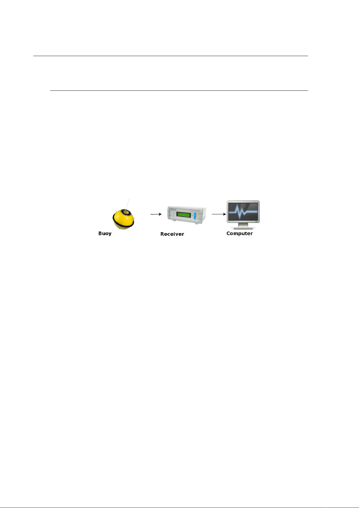
This section describes the setup for the basic system as shown in the figure below
Example of a basic network
The network consists of:
Buoy The deployed DWR4 buoy using the HF-link.
Receiver An RX-C receiver using the Ethernet connection.
Computer The computer receives, processes, and displays the data of the Buoy. On this
computer the following parts of the Waves4 suite are installed:
•buoyd
•waved
•Waves4 configurator
•Waves4
In this setup the user has only one buoy, but this can be scaled with multiple buoys.

9
7.1.2 Extended
The network consists of:
Buoys Buoy 1 A deployed DWR4 buoy using the HF-link.
Buoy 2 A deployed DWR4 buoy using the HF-link.
Buoy 3 A deployed DWR4 buoy using the iBuoy communication option.
Buoy 4 A deployed DWR4 buoy using the iBuoy communication option.
Example of an extended network
Receivers
Receiver 1 An RX-C receiver using the serial connection.
Receiver 2 An RX-C receiver using the Ethernet connection.
Acquisition systems
Computer A1 The computer receives the data of Buoy 1. On this computer the
following parts of the Waves4 suite are installed:
•buoyd, using the A1 as ID of the buoyd instance.
Computer A2 The computer receives the data of Buoy 2, Buoy 3, and Buoy 4. On this
computer the following parts of the Waves4 suite are installed:
•buoyd, using the A2 as ID of the buoyd instance.
Processing systems
Server P1 The computer processes the data of Buoy 1, Buoy 2, Buoy 3, Buoy 4. On this
computer the following parts of the Waves4 suite are installed:
•waved
Note there should be only one system running waved in a network.

10
Display systems
Computer D1 The computer displays the data of Buoy 1, Buoy 2, Buoy 3, Buoy 4. On
this computer the following parts of the Waves4 suite are installed:
•Waves4
Computer D2 The computer displays the data of Buoy 1, Buoy 2, Buoy 3, Buoy 4. This
system is also used by the operator of the Waves4 suite. This user configures the
settings of the campaigns in buoyd and waved. On this computer the following parts
of the Waves4 suite are installed:
•Waves4 configurator
•Waves4
Computer D3 The computer displays the data of Buoy 1, Buoy 2, Buoy 3, Buoy 4. On
this computer the following parts of the Waves4 suite are installed:
•Waves4
In this example the HF-receivers are received with two systems. It is also possible to receive
them on a single computer system with one buoyd service running. This depends on whether the
RX-C4 receivers are at one or multiple physical locations. (With Ethernet it is possible to place
the acquisition system at a different location as the RX-C4 receiver, but in case of network
issues data will be lost.)
The system running the waved service is a separate server, it is also possible to put this on an
acquisition machine. It would also be possible to install the Waves4-configurator on this
machine.
For further information, please consult the Waves4 user and operator manual:
http://www.datawell.nl/Support/Documentation/Manuals.aspx

11
8 Mooring preparation (not for DWR-G4)
Even though the mooring is no sensor by itself, it is a crucial part of a wave measuring system.
It solves the paradox of keeping the buoy on its location while at the same time allowing the
buoy to follow the orbital wave motion.
Your mooring has been shipped to you pre-assembled as far as possible. The only things you
have to do are:
(1) adjust the Polypropylene line to the correct length and attach the yellow float according
manual (page 70-73) and connect the terminals (page 64)
(2) attach the sinker weight or chain to the P- rope according manual (page 70-73)
(3) connect the P- rope end with the yellow float to the anchor weight using the 25 mm
shackle provided and connect the other end to the rubber cord.
(4) connect the rubber cord to the buoy chain
(5) connect orange float(s) if required (only for mooring depth 8-34 m DWR or 8-17 WR)
After fastening the nut on the shackle bolt it must be secured from
unscrewing by applying a split pin. Push both legs of the split pin
through the hole in the bolt and bend them back, one leg round
each side of the bolt. Bring a suitable pair of pliers and a few spare
split pins (included).
To avoid entangling the mooring line, lay it out on the deck of the ship as a stack of ‘eights’. To
keep everything in place you may tie a rope around the waist, leaving one loop of the ‘eight’ on
either side, and two ropes through the two loops itself. If you are taking off rope or wire from a
reel, do not slide off loops on the side but unroll the reel. Sliding off line will build up a torque
that may set the buoy spinning and damage the sensors of the WR-SG and DWR-MkIII.
In practice, all these actions will be taken when the ship has already left the port. However, to
avoid problems at sea please inspect the mooring once before you actually deploy the buoy. If
this is your first buoy deployment, lay out the mooring on land at ease as an exercise, study it
and pack it into the blue containers again.
9 Buoy Deployment
Now that you have set up and checked the equipment on land, it’s time to deploy the buoy. A
safe and successful deployment requires the right equipment and a well-thought out procedure.
Bring a few ropes and a knife, they always come in handy. Also bring a used car-tire to support
the buoy while on deck. Still the buoy must be roped to the railing. If you have a Buoyfinder
you can use it to monitor the buoys outputs. Alternatively you can radio contact your receiving
station during deployment. The best time to do this is after the buoy is deployed on its location
and before the ship will return to port. To handle the weight of the sinker, either a ship with a
hoisting crane or U-frame or a ship with a removable railing should be chartered. For
comfortable deployment a day with small waves is best waited for.
The procedure below, see pictures, is suggested for a small vessel with a hoisting crane or
removable railing in the front. Users should adapt the procedure to size and outfit of their ship
and according to their own experience. Before the actual deployment lay out the mooring line
on deck and connect it to sinker and buoy using the shackles and split pins. Never stand inside
the loops of the mooring line or between the mooring line and the ship sides. Hoist the sinker on
the side of the ship and hang it overboard on a rope or push it towards the removable railing.
Release the sinker weight from the hoisting crane and leave it hanging overboard. Once you are
at the intended location steer the ship in reverse backing up slowly against the current. This
manoeuvre will keep the mooring line out of the screw propeller. Deploy the buoy by hoisting
or pushing it overboard. If you hoist the buoy use an extra piece of rope to keep the crane hook
at a distance from the antennas and sensors mounted. To release, cut the rope. Feed the mooring

12
line loop by loop while the buoy drifts away from the ship and finally cut the rope that carries
the sinker or push the sinker overboard. Continue to back up until the ship has gained enough
distance to steer clear of the buoy and mooring line.
Should anything go wrong, do not recover the buoy by pulling on the rubber cords. This is
dangerous. If you can reach the polypropylene rope, you may pull directly at this point. If you
necessarily have to recover the buoy and you can only reach the rubber cords, cut the rubber
cord.

13
10 Buoy Recovery
IMPORTANT – During the recovery process the most dangerous item is the rubber
cord(s). Stretching the cord(s) increases the level of danger and should be avoided
whenever possible.
There are several techniques for recovering a Waverider buoy. The most suitable method on any
particular occasion will depend on the location, the weather, the sea state, the type/size of vessel
being used, the availability of substitute equipment and, sometimes, operator
experience/preference.
The general methodology is to recover the buoy first, then the rubber cord(s) and finally the
clump weight, which should be lifted via the polypropylene rope. Do not lift the mooring with
the rubber cord(s).
The rubber cord is a valuable item. Minimise the risk of damage after recovery by handling it
carefully and stowed it away from operating areas as soon as practically possible.
(a) Method - Exchanging Waverider buoys at the same location
If the operating vessel has the ability to maintain its position in relationship to the Waverider
mooring without extending the rubber cord during the recovery process, this is the quickest
method of exchanging a buoy deployed at the same mooring:
Lift the buoy from the water using a rope bridal, connected between the two handles fitted to the
upper half of the Waverider buoy hull. Steady or anti-spin lines can be attached to the safety
triangle during the lifting procedure. Stow and secure the buoy on the vessel deck. Secure the
mooring to the deck at the upper end of the Polypropylene rope.
Disconnect the mooring between the chain coupling of the buoy and the rubber cord terminal.
Connect the mooring to the chain coupling of the replacement buoy, ensuring that the safety
shackle is correctly fitted and securely locked with nut and split pin.
Free all securing lines to the mooring and the Waverider buoy, lift the buoy and lower back onto
the water.
During the above operation a member of the recovery team, equipped with a knife, should be
stationed close to the secured rubber cord. Should any sudden vessel movement increases the
tension in the rubber cord and endanger the recovery personnel, the rubber cord must be
severed.
It should be noted that this mode of operation may only be used where the ship is able to
maintain its exact position within a couple of meters. Additionally this method does not allow
all the mooring to be fully inspected (the rubber cord(s) for cuts and polypropylene rope for
wear). If this method is regularly used, increased inspections of the complete mooring must be
undertaken.
(b) Method - Recovery using a dummy buoy
Where there is no replacement Waverider buoy, a dummy buoy can be deployed to support the
mooring thus avoiding the need to retrieve the complete mooring. An old Waverider equipped
with an operating flashlight may used as a dummy buoy. In this instance the exchange
procedure described in a) above has to be applied twice.
(c) Method - Recovery using a small work boat, rib or dingy
The Waverider cannot be lifted onto a small workboat or rib. However, such a vessel may be
used to tow the Waverider buoy to a larger vessel or ashore. Mooring recovery will be by hand,
ensuring that no tension is placed on the rubber cord(s). Recovery of the mooring clump weight
must only be achieved by using the polypropylene rope.
If the mooring clump weight cannot be recovered, the polypropylene rope may be cut below the
rubber cord leaving the clump weight and residue rope on the seabed.
The Waverider should not be towed at speeds greater than 2 m/s (4 kn).
By using this recovery method, the cost of the loss of a section of mooring line and clump
weight would be more than offset by the savings made in not chartering a ship.
This manual suits for next models
5
Table of contents


