Daum electronic Vita 2002 PC de luxe User manual


watt
))
)
))
)
188
OK
0
88.8
88.8
8
:
88. .8
8
:
88. .8
1
2
3
4
5
6
16
7
17
8
9
10 1112 13
14
15
1. LCD-Display 2. LCD-Display 16. LCD Graphic Display
3. LCD-Display
4. LCD-Display
5. LCD-Display
6. Control button
7. Relax sensor connector
8. Pulse sensor connector /
Ear clip
9. fitness key
User
Pulse rate
Pulse status
Program number
Program display
Braking power in Watt
Relax status
User number
Program selection
Relax status
Diagrams / trainings programs
Initialization / time, date
Team Award
Coaching processes
Pedal speed
(RPM)
Distance
Total kilometers
per user
Distance covered
Average speed
Kilojoule burned
Training time
Fitness grade
Limit values for
Kilojoule burned
and training duration
10. reset key
11. dat key
12. prog key
13. relax key
16. LCD Graphic Display
17. PC Interface connector
18. RESET key (recessed)
14. coach key
15. Gear shift
18
The Dashboard
(Underneath)
(Underneath the dashboard)

A
A. Miscellaneous
F. Training programs
What is an ergometer?
About this manual
setting the language, time, and date
Dashboard serial number, Team Award
About the graphic display
Sample display screens
C. The dashboard
Switching On/Off
SLP-Mode (Stand by)
B. Setting up
E. Training
D. Preparing for training M. Assembling the unit
i. Initialization
L. LCD Graphic Display
W. Maintenance
T. Technical information
S. Index
Control button No. 6
Function keys / input connectors
Window No.1 / Selecting user ID
number and guest user
Window No. 1 / Pulse rate
aerobic pulse zone
Heart pulse rate / aerobic range
Window No. 2 / Time and KJoule
Window No. 3 / RPM
No. 4 / km/h and user km total
Window No. 4 / Distance and km limit
No. 5 / Watt and Relax
Pulse sensor / Cardio Sensor Chest band
PC-interface,
PC-software ergo_win 2002
Manual setting “0”
General recommendations about training
Safety hints about training
Manual training
Fitness test / fitness grade
Recalling fitness and training values
Relaxing / relaxation function
Installation hints / Miscellaneous
Unpacking / contents
Mounting instructions / mounting the feet
Accessory / “swing-feet”
Assembly / mounting the handle column
/ mounting the dashboard
/ mounting the saddle
/ mounting the pedals
Fine tuning
Cleaning and care
Simple maintenance and service
Replacing the V-belt
Spare parts / overview (cut away drawing)
Spare parts list
Dashboard replacement
Special accessory / Cardio Sensor Chest band
Technical data
Safety requirements / conformity
Glossary
What to do if.....?
§. Warranty conditions
Fold out page
Table of contents
The dashboard/ Overview of the control
elements
Page Page
FO
A
B
1
2
3 - 13
3
4
5
6
7
8
9
10
24 - 57
11
12
13
14
14,
15
16,
17
18-23
14-17
18
19
20
21
22
23
M1 - M12
i1 - i2
L1 - L2
M 1
M 2
M 3
M 4-M 7
M 11-M12
M 8-M 9
M 9-M10
M 11
M 12
W1 - W5
W 1
W 2
W 3
W 4
W 5
T1 - T3
T 1
T 2
T 3
G. Glossary / Appendix G1-G3
S1 - S2
G2-G3
G1
Setting user identification number
setting personal data and alarm values
data entry, personal settings
A
26
27
28 - 30
28
29
29
30
31
31
31
32 - 35
36 - 37
40 - 41
43 - 45
46 - 50
51 - 53
54 - 55
i1 - i2
38 - 39
39
42
48
56
56
57
i2
L1
L2
24
25
Programs overview / by model
Programs overview / Setting - display
Selecting the training program
Cardio Program / C
Individual Program / P
Pulse Individual program / IP
Watt Individual program / IL
Speed Individual program / Ir
Selection and programming
Intensification program /L
Constant RPM /A
Strength program /H
Training diagrams watt controlled (400 watts)
Training diagrams pulse controlled
Cool-Down Programs
Cool-Down Diagrams
Training programs watt controlled (400 watts)
Competition circuit
Tour de France (21 stages)
Conconi Test
Conconi Test protocol
Copy models IL / IP / Ir Programs
Gear shift
Starting the training programs at a later point
Determining weight and body fat
ergo_bike Team Award
Table of contents
H1 - H14
H1 - H2
H2
H7 - H11
H8 - H11
H3
H4
H5
H6
H7 - H8
H12
General and fundamental information about
Coaching
Preparing for Coaching training
Personal data, performace evaluation
First training, setting the training type
Displaying the training plan and units
Taking performance test (WHO Standard)
Training after the performance test
Running the training units, training control
Deviation from training plan, downgrading
Entry and performance test / WHO Standard
Training samples
H. Coaching
H13-H14

ergo bike
Visit us on Internet!
www.daum-electronic.de
Your password for the service area:
“ergo-service”
Notes about Software Update
The heart of the dashboard consists of a modern Flash ROM Processor
It allows upgrading all the software related functions, training
programs and fitness tests to the latest release,
even years from now.
The latest software is available for download at the ergo_bike
homepage on Internet and can be transfered to the dashboard
with the ergo_win 2002 PC program
You will find the instructions for this operation in the
the software.
“read me” file
that comes with

1
ergo bike
1
ergo_bike Model
Introduction
What is an ergometer bike?
This ergometer is specially designed for health and endurance training. High quality manuf-
acturing, easy to see dashboard, ease of use and maintenance all contribute to make this
appliance an ideal training device for sport and fitness purposes. Also note that the complete
equipment and the wide performance range should appeal to sport or fitness conscious
persons of every age group.
A full electronically controlled, maintenance free, eddy current break is at the heart of the
ergo_bike. It adjusts the load according to the values determined by the computer to fit the
strictly personal requirements, and allows a continuous load value selection from 25 to
400 Watt.
The ergometer is thus more than a “Home Trainer”,
since it can be used for both sports and therapeutic objectives.
ergo_bike “vita 2002 pc de luxe”
About this manual
You will find an explanation of the concepts
and expression that are new to you in the
Glossary in the appendix.
This load is then maintained independently of the speed expressed in revolutions per
minute (within the RPM ranges shown on the graph on page 9), which means it is possible
to train with a load that is considerably independent of the pedaling RPM. This feature
prevents an unwitting exposure to incorrect loads while training.
The cover of this manual contains a foldout page. This greatly simplifies the general
manipulations and the location of the display and control components on the folded out page.
An appropriate symbol is used to identify
various important information and remarks.
Please read them carefully.
The present instruction manual describes the
The ergo_bike was developped and manufactured in accordance with the standard
A DIN EN 957-1/5 (formerly DIN 32932/A), and is therefore suitable for therapeutic purposes.
The ability to prescribe the required power load in Watt beforehand is an essential
feature of an ergometer.

2
)))
SLP
watt
2
Upon turning on the power switch (On/Off),
the six display windows of the dashboard
will display all the symbols and number
segments for about eight seconds. This is
a self test run by the computer on the entire system.
The ergo_bike switches automatically to stand by mode if it is left switched on and
unused for about two hours. This is signaled by three beep sounds and ten times blinking
of all the windows, and by the display of “SLP” in window number 2. All other windows
are blanked. This mode is terminated by pressing control button number 6.
The graphic display (window no. 6) provides for more
functional and visual convenience. Displaying training
diagrams, user guidance and hints are functions that
can only be displayed on a graphic display.
Window no. 6
LCD Graphic Display
See page L1 for
explanation about
the display
The dashboard of the “vita 2002 pc de luxe” shows
a Graphic LCD in its centre (see page 4). You will find
a special description of this equipment part and
its operation in appendix L (LCD Graphic Display).
U-shaped
perforated plate
General information
Setting up
Switching On / Off
Please read the Notes on Safety (page 19)
before switching the ergo_bike on, and follow
the installation and assembly instructions
(pages M1 - M12).
The On/Off switch (power switch) is located
at the back in a rectangular plastic frame on
the rear perforated plate cover.
(power switch)
On / Off
The ergo_bike should be switched off by mean of the
On/Off switch or by pulling the power cord plug
from the power outlet.
(This does not apply for the values of the “guest” user.)
Always press the Reset key before switching the
device off in order to save the distance covered
in kilometers.
“Stand-By mode” ( SLP )
Display-
window
Window no. 2
Please note:
The value of the daily kilometer counter (the wide arrow pointing to Distance) will
always be added to the total kilometer counter (the arrow pointing to User/Km Total),
1. if the ergo_bike goes in Stand By mode ( SLP-Mode ).
2. or if the Reset key is pressed, or when
3. another person starts a session and another user identification number is selected.

watt
)))
)))
188
OK
0
88.8
88.8
8
:
88. .8
8
:
88. .8
33
Entry / Function A :
in one year increment
Male (M) / Female (F)
in one cm
in 0.5 kg
in one beat per min increment
in one minute increment
in one kilometer increment
in ten kilojoules increment
Menu control / scroll function
increment
increment
in 0.5 percent increment
in level unit increment
in number of days
in five watts increment
Age
Sex
Height
Weight
Body fat content
Individual performance rating
Training frequency
Pulse rate
Time
Distance
KJoules
Coaching program
Watts
Two functions in one button!
A:
B:
Control button no. 6 is the central control element of the ergo_bike.
Turning the control button:
Pressing the control button:
Changes the value displayed in
the active display window
Stores the value selected by turning
the button
Changing the display between Time/km/h
and KJoule/Distance
Changing to the next data to enter
Activates when in the
SLP mode
the ergo_bike
Instructions to turn the control button are indicated in this manual
by this symbol
Usage
Control Button No. 6
The Dashboard
Instructions to press the control button are indicated in this manual
Entry mode / Function B :
confirming and storing
of the data (pages 16/17)
when setting personal data
To change the display from Time / km/h
to the display of KJoule / Distance
when switching or selecting / in general
while training
( see page 8 )
by this symbol

9
10
14 11
12 13
17
18
watt
)))
)))
8
6
16
7
15
4
15. Derailleur control
14. coach key
keys used to control the electronic “gear-shift” system.
Used to set the Coaching program.
(page 54, 55)
(page H4, H6-H7, H12)
Window no. 6
(see appendix L)
LCD Graphic Display
(see page 12)
16. LCD graphic display provides functional and visual comfort.
(see appendix L for a description / LCD-Graphic display).
(see pages L1 - L2)
Window no. 6
(see pages 16, 26/27, H4)
(see pages 26/27, 39, 31)
(see page 23)
(see pages 2,14,16, 23, 26, 30, H4, H5, H7)
(see pages 5, 6, 8-10)
(3)see page
7. Connector of the relax sensor
6. Control button
1. - 5. LCD Displays
8. Connector of the pulse sensor
used to connect the relax sensor.
(see page 23 / "to relax" )
used to connect the pulse sensor /
earclip (see page 11)
9. fitness - key
10. reset - key
13. relax - key
11. dat- key
12. prog - key
Resets the display windows.
allows the entry of personal data that will be
used to determine the alarm values to be monitored
during training sessions
This key is used to recall the programmed training
sessions. (see page 26)
Starts the relax program used with the relax
sensor (accessory).
Control elements of the dashboard
(has 2 functions / pages 21, 22) 1.
2.
Recalls a fitness mark
Recalls the values of the last training session
(see page 21)
(see page 22)
17. Connector
PC-interface
The PC interface (connector) is located on the
underside of the dashboard within the square
opening (see page 12)
Displays / Function keys / Input connectors
The Dashboard
Window no. 2 Window no. 4
Window no. 1
Window no. 3 Window no. 5
Display windows no. 1 to 5
(below)
(see page G3)
18. RESET - key (recessed)
for the dashboard computer
The RESET key is located on the underside of the dash-
board, above the protective plate and is intended to be used
in the case of a failure of the internal computer software.
what if...?
(below)

watt
watt
User:
User:
guest
guest
5
3.
2.
188
OK
00
1.
reset
CC
)))
3054
5
00
prog
Before using the equipment, you must assign
a user number to every user.
The ergo_bike computer will record, store and evaluate
the training data of up to four users separately.
Guest users, or any persons, whose training data will not be saved, should use identification
number “0”. When using this ID number the arrow pointing to User 1 to 4 will not
be displayed. Instead the number “0” is displayed under .
No training data will be saved for the “Guest” user when the ergo_bike is turned off!
However, the distance traveled in kilometers will be added to the total kilometer
counter (km-total).
Turn, (to the right or left) until
the blinking user arrow
points to the required user number
or “0” blinks under prog
1 x
Press
Window no. 1
Changing the selection
Window 1
- the right arrow points to
the selected program
and the program number
is displayed under prog, e.g. C
- the total number
of travelled kilometres,
e.g. 3054km
Window no. 6
The graphic display
(window no. 6)
will simultaneously
display the setup
procedure as shown
to the right
The graphic display
(window No. 6) will
simultaneously display
the setup procedure
as shown to the right.
(see appendix L)
LCD graphic display
press repeatedly until the
user arrow or the “0”
under prog starts to flash the user arrow
or blinks
00
Either
Window 1
Window 4
Set up of the User identification number 1 to 4 or Guest 0
- the left arrow points to the
selected user number, e.g. 3
User instruction
Window No. 1
1. Selecting the user
identification number
The Dashboard
Mother Father Daughter Son
User 1 User 2 User 3 User 4
The following is an example of a possible number attribution scheme in a family:
Window no. 6
The settings are confirmed
and saved
User 1 - 4 or e.g. Guest 0

6
120
OK
00
110
00
110
160
68
199
6
Displaying the aerobic pulse zone
Displaying the pulse rate
The pulse rate or pulse status
is only displayed if the pulse sensor
(ear clip) or the cardio chest band is
connected or when both hand are holding
the pulse sensors (on the handle).
actual
pulse rate
Window No. 1
If the user is training within the aerobic rate zone,
“OK ” is displayed in window No. 1 (beside the blinking heart ).
a blinking heart
indicates that the pulse
sensor (ear clip) or the
Cardio chest band
is correctly connected
and functioning,
or that both hands are holding the hand pulse sensors.
Selected program
(simplified representation)
The upward pointing arrow indicates
The downward pointing arrow indicates
The downward pointing arrow starts blinking
to indicate that the aerobic rate zone is exceeded by an
excessive margin (the danger-zone is reached),
and the user risks injury by overexercising.
The aerobic zone is a function of the age, it can be determined on the graph
“Target pulse frequency” and the table “target zones of heart frequency” (page 7).
The aerobic pulse zone is only displayed if the user enters his age.
(see page 16 / personal data / alarm levels / age entry )
that the user is training below the aerobic zone. To get to the “OK ” zone
the user must either train longer and/or increase
the braking power in Watt.
that the user is training above the aerobic pulse rate zone.
To get to the “ OK ” zone the user must reduce
the braking power in Watt.
A beep sound combined to the downward blinking arrow
indicates that the user has reached the “alarm zone”.
The ergo_bike starts reducing the braking power automatically
at a rate of 5 Watt per second until the pulse rate of the user
falls into the “danger-zone”.
If the training session is program controlled, and if the training is , the watt setting
will automatically reduced by the same reduction needed to bring the pulse rate to the “danger zone”!
carried on
be
blinking arrow!
and
Beep
Window 1
Heart pulse rate
Window No. 1
The Dashboard

60%-75% 76%-85% 86%-100%
20 40 - 119 120 - 150 151 - 170 171 - 200
25 40 - 116 117 - 146 147 - 165 166 - 195
30 40 - 113 114 - 142 143 - 161 162 - 190
35 40 - 110 111 - 138 139 - 157 158 - 185
40 40 - 107 108 - 135 136 - 153 154 - 180
45 40 - 104 105 - 131 132 - 148 149 - 175
50 40 - 101 102 - 127 128 - 144 145 - 170
55 40 - 98 99 - 123 124 - 140 141 - 165
60 40 - 95 96 - 120 121 - 136 137 - 160
65 40 - 92 93 - 116 117 - 131 132 - 155
70 40 - 90 91 - 113 114 - 127 128 - 150
75 40 - 86 87 - 109 110 - 123 124 - 145
OK
70
80
90
100
110
120
130
140
150
160
170
180
190
200
20 25 30 35 40 45 50 55 60 65 70
100%
85%
60%
OK
75%
77
up to 59%
Table of target heart rate zone / aerobic zone
Target zone of heat rate frequency to the maximum heart rate
If the braking power is reduced by, e.g., 50 Watt in the danger zone, and the value set for the next
program step is, e.g., 150 Watt, then the training will in fact be carried forward with a load
of 100 Watt, as will be shown in the Watt display (window No. 5). The computer makes this
adjustment as a safety measure.
Alarm Zone
Danger Zone
Aerobic Zone
Beep sound
Danger Zone
above the
The braking
power will
automatically
be reduced!
Age
Overview diagram of the target heart frequency rate
Example
for a person 50 years old
Heart rate 40 - 101
Alarm Zone
Heart rate 128 - 144
Danger Zone
Heart rate 145 - 170
Heart rate above 171
Aerobic Zone
Heart rate 102 - 127
Health
danger !
Alarm Zone
Danger Zone
Aerobic Zone
heart rate
Age
Heart rate frequencies / aerobic zone
Beep signal

0
:
30 0
0
:
30 0
500
500
1 x
8
)))
)))
)))
)))
)))
)))
)))
)))
)))
)))
8
:
88. .8
8
Window 2
Displays :
1. Training time
1a. Time limit
2a. kJoule limit
2. kJoule
(see also pages 14 - 17 / the section on training preparations “personal data / Alarm levels”
or entering the preset values and “Settings verification”)
Switching between the time and kJoule display using control button no. 6
Display example
Training duration of 30 minutes
kJoule kJoule
Time Time
the actual training time
the preselected alarm time
the reaching of a time limit (time limit arrow)
the actual kjoule burned
the preselected kjoule limit
the actual clock time
When the selection arrow is pointing to the clock symbol:
When the selection arrow points to kJoule then:
the elapsed training time is displayed (max. 9 hr 59 min)
the energy spend in kJoule
Selection arrow
kJoule limit arrow
The time limit arrow is displayed when the preset time
limit is reached.
The kJoule limit arrow is displayed when the preset
kJoule limit is reached.
This arrows indicates that the preset time limit has
been reached or exceeded. Additionally the system
emits an acoustic signal.
This arrows indicates that the preset kJoule limit has
been reached or exceeded. Additionally the system
emits an acoustic signal.
is displayed.
Acoustic signal
Acoustic signal
Selection arrow
time limit arrow
Training time and kJoule
Window No. 2
(display in minutes/seconds)
The Dashboard

99
)))
100
)))
)))
25
3054
57
3 0
40
5 0
6 0
7 0
8 0
9 0
1
1
1
0
2
1
0
0
0
252 0 03 0 04 0 0
1 0 0
Watt
Window 3
Window 4
RPM (Pedals revolutions
per minute)
The is independent of the RPM in the RPM ranges
shown in the diagram to the right. This means that the user
will have to provide an effort corresponding to the displayed
Watt-power .
ergo_bike
, within the actual RPM range
Displays:
The user is pedaling too fast
(It is then possible that the displayed power
in Watt is not exactly true).
The user is pedaling too slow
(It is then possible that the displayed power
in Watt is not exactly true).
The arrow points to the minus sign
to indicate that
The arrow points to the plus sign
to indicate that
The power is indicated precision
of about 10% in the RPM ranges delimited
by the arrows
in watt to a
+
__
Selection arrow
1. km/h
When the selection arrow is pointing to km/h
the displays shows:
the actual speed
the average speed.
(when reviewing the values of the last training session)
Displays:
km/h
Users / km total
Distance
The reaching of a distance limit
2. Users / km total
When the selection arrow is pointing to Users / km total
the displays shows:
the total number of kilometers covered by the user or
under the specified user identification number (for
the whole life of the ergo_bike). Arrow
Speed
Power
Watt Relax
RPM / km/h and km total
Windows No. 3 & No. 4
The Dashboard

1 x
10
)))
15
60
400
150
180
10
Window 5
Selection arrow
3. Distance
Distance km/h Distance km/h
Switching between the km/h and distance display using button no. 6
When the selection arrow is pointing to the km/dist:
the distance in km covered during the present training session
is displayed.
Selection arrow
Distance limit arrow
3a. Limit ( km )
acoustic signal
The distance limit arrow is displayed when the preset
distance limit is reached.
This arrows indicates that the preset distance limit has
been reached or exceeded. Additionally the system
emits an acoustic signal.
Displays:
1. Watt
2. Relax
the braking power in Watt
When the selection arrow is pointing to the Watt:
When the selection arrow is pointing to the Relax:
a Relax level, between 0 and 255
the braking power in Watt (25 to 400 Watts)
is displayed.
is displayed.
Distance/Watt & Relax
Window No. 4 and No. 5Window
Distance and reaching of a distance limit
Selection arrow
a Relax level
The Dashboard

111111
Pulse sensors / Cardio sensor chest band
The pulse sensor (ear clip) included in the package is an important accessory to
the ergo_bike. You should not start any training session without it, or without the Cardio
sensor chest band available as an option ! The pulse sensors built into the handle can
be used to control or monitor the heart rate over short periods of time.
ergo_bike
Special accessory
You will find a precise description of the display
and the meaning of the corresponding display
symbols on page 6 (Displaying pulse status). available from:
The wireless Cardio sensor chest band
(see the figure to the right), available as an
optional accessory (order number 90 91 015),
permits more precise measurements.
( See page T 1 )
All ergo_bike ergometers are equipped with a built-in, not visible from the outside, Cardio pulse receiver.
This allows receiving of the pulse rate transmitted by any standard chest band, of the coded and non-
coded type. You only need a cardio sensor chest band (see page T1) to achieve wireless heart rate
measurement.
Warning: using two chest bands simultaneously in the same room, either of the coded or non-
coded type, to achieve wireless heart rate measurement can lead to the display of a wrong pulse
rate on the dashboard of the ergo_bike.
Standard accessory (included in the box)
ergo_bike pulse sensor (ear clip)
Ear clip
connector
Built-in
Cardio pulse
receiver
wireless
Cardio sensor chest band
Order Nr. 90 91 015
Cardio
sensor
chest band
(with transmitter)
Pulse measurement over the hand surface
The sensors built in the handle are used to control and monitor the pulse rate over short periods of time. To
achieve a correct measure you should lay your hands relaxed and loose (not tight) on the electrodes. The
electrical resistance of the skin varies as a consequence of blood pressure variations due to heart pulses.
These variations are measured by the electrodes and displayed as heart rate on the dashboard.
The ear clip pulse sensor illuminates the ear lobe to measure
the pulse rate. Every heart pulse modulates the light passing through the lobe, and can thus be detected
by an infrared sensor and displayed as heart pulse rate. Built in hand pulse sensor
left and right of the handle
(standard equipment)
2.
3.
Insert the connector into the socket no. 8
on the dashboard marked with .
1.
Attach the pulse sensor (ear clip) to
the ear lobe so that the two contact surfaces
sit entirely on the skin. The heart symbol in
display window 1 starts blinking to
indicate that the ear clip is properly attached
and functional!
You should rub the ear lobe energetically
with your fingers to stimulate blood circulation.
Warning!
Strong light sources, like sunlight, halogen
projectors or neon lamps, and also ear piercing
or ear rings, and the intake of beta-blocker
could affect the measurements!
Pulse sensor (ear clip)
Advice: If measuring the pulse rate over the hand electrodes gives no results, we recommend using
either the ear clip method or the Cardio sensor chest band. The variations of the electrical
resistance of the skin are so small for some persons that they cannot be used to acquire any
usable results.
The Dashboard

17.
1212
Connector
PC Interface
(Underside)
order from:
ergo_win 2002
Order Nr. 90 91 012
(PC-Software for the communication with the ergo_bike 2002 pc)
Description
PC Interface
The training support provided by the
ergo_win 2002 software was specially
developed for the daum electronic
ergometers of the 2002 pc series.
Features highlights:
Comprises:
Internet capable.
Animated races against oneself, against a computer opponent, against another
ergometer or an internet training partner in real time.
Uncountable number of training programs through exchange and
download possibilities over Internet.
Extremely simplified programming of your own watt and pulse controlled program profiles.
Tour planing for distance controlled training programs.
Extended weight and body fat analysis.
Fully automatic Conconi test / PWC test
Extended training evaluations
Possibility to export all the data to other programs, e.g. Excel.
Extended Coaching functions
User management with individually configurable user interface.
Saving, evaluation and archiving of all the training data.
Provides a wealth of background information on topics of sport medicine
and sport physiology.
Modern user interface.
Simple operation.
CD-Rom
Interface cable
Pentium processor
20 MB free hard disk space
Available serial (Com) port
CD-ROM drive
Keyboard
Operating system: Windows 98 / ME
Hardware requirements (minimal requirements)
Windows 2000 / NT
The Dashboard

00
watt
)))
)))
13
LCD Graphic Display
(see appendix L)
Window no. 4
Window no. 5
Window no. 1
Window no. 2
Window no. 3
Window no. 6
Manual setting “0”
When the ergo_bike is switched on (using
the power switch), or when the “SLP” state
(sleep mode) is canceled using control
button No. 6, it goes into ready state.
You can directly start training without
the need to do any particular setting!
Window no. 2
Window no. 3
Window no. 4
Window no. 5
Window no. 6
the actual theoretical velocity (km/h)
the actual load setting (in Watt)
and the Relax levels
the elapsed time since the beginning of the training.
RPM the actual speed of the pedals in revolutions per min.
The following symbols/numbers in display
window no. 1 mean that the ergo_bike is set
in manual mode for the indicated user number,
and without the entry of any personal alarm values:
This symbol means start
operating / turning the
pedals.
Basic set up
Display windows
Heart pulse rate
Window no. 1 (this value is only displayed if the pulse sensor
Values displayed in the dashboard windows during a training session:
When you start moving the pedals display windows no. 2,
4and 5 show the actual training values.
The smallest load value for a training with the ergo_bike is 25 Watts.
You can increase or decrease the load in five Watts increments by turning the
control button no. 6.
(ear clip) or the Cardio Sensor chest band is connected and functional)
The pulse frequency will be displayed in window no. 1 when the pulse sensor (ear clip),
or the Cardio Sensor chest band, is connected and functional or when both hands are laid
on the hand pulse sensors on the handle.
Window no. 1
Symbols
graphical representation of the training session
and operating menus
The Dashboard

14
1.
11
)))
3054
reset
14
See the notes about evaluating your own performance level
in chapter H (Coaching), page H3.
blinks
See page 5 for a more detailed description of the setting procedure,
see appendix L for explanations about the graphic display.
Window no. 6
Training efficiency and control of over and under loading can only be
achieved when the personal data are entered.
Possible entries:
Every user should always enter his age when training with the ergo_bike, since it is a significant
figure for the determination of the load requirement and for the corresponding fitness evaluation.
1. User identification allocation
2. Setting up personal data and alarm levels
About the age entry
The computer of the records, saves and evaluates, separately the training
data of up to four users (user identification number 1 to 4).
ergo_bike
Additionally, guests or other users, whose training data should not be stored,
can train under user identification number “0”.
(see page 5)
1.1Selection of the user ID number User (1 to 4) + Guest
The computer of the ergo_bike compares these entries with the actual training
values and evaluates them accordingly.
DF = Default value
Entry sequence
for the alarm values
DF 00:00
Age
Sexe
Height
Weight
Body fat content
personal performance
evaluation
Training frequency
Watt upper limit
Upper limit for
heart pulse rate
training duration
distance
Kilojoule burning
for example 45 years
male / female M or F
for example 180 cm
for example 70.0 kg
for example 30.0
for example 0 = beginner
3 = very well trained
for example 4 days
for example 200 Watt
for example 115 beats
for example 25 min.
for example 15 km
for example 350 kJoule
(Confirm with a physician and do not exceed
the recommended value )
(from 10 to 99)
(from 100 to 220)
(from 30.0 to 150.0)
(from 0.0 to 55.0)
(from 0 to 3)
(from 3 to 7 days)
(from 25 to 400)
(from 80 to 220)
(from 00:00 to 99:99)
(from 0 to 99)
(from 0 to 1000)
DF 40
DF = F
DF 180
DF 70,0
DF 30,0
DF400
DF 220
DF 0
DF 0
DF 0
DF 3
User arrow
Window no. 1 - The left side arrow points
to the selected user number,
e.g. User number 3
- The program number
is displayed under prog - the total number
of traveled kilometers
Window no. 4
The graphic display shows
the number 3 in reverse
(negative). This means user
number 3 is selected.
watt
User:
guest
Preparing for training
Personal settings Training
press repeatedly until the
user arrow is blinking
in window no. 1

15
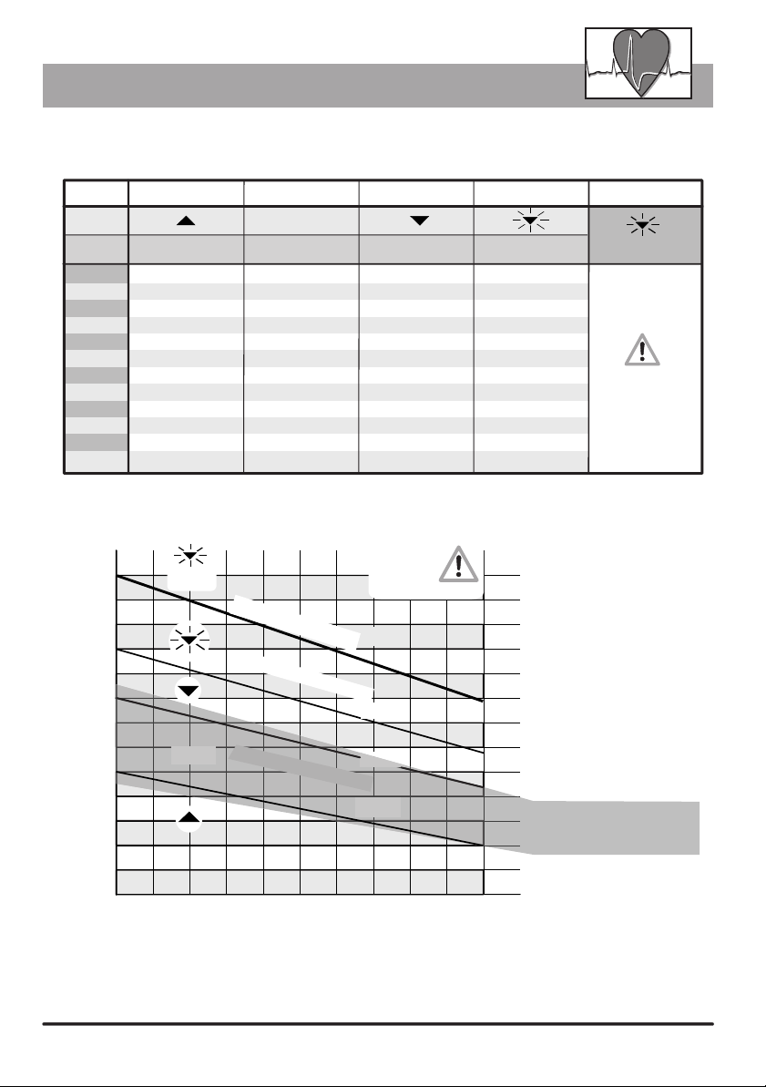
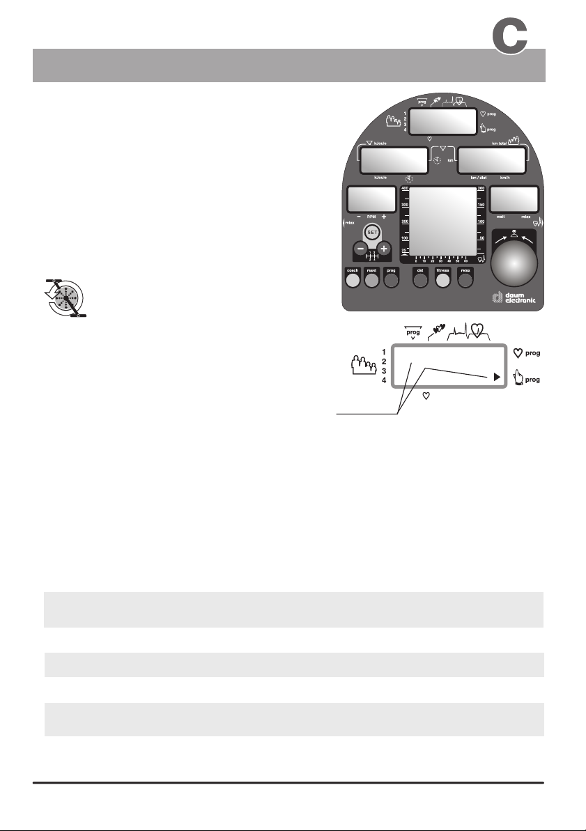
The warns you when the limit pulse rate is exceeded and the danger zone is reached, by displaying
a blinking arrow in window no. 1, and by an additional beep sound when you enter the alarm zone.
ergo_bike
Users should preferably consult a physician to determine the reasonably acceptable personal pulse rate.
(see also page 7 / Table and diagram of the target pulse rate)
for burning fat 160 - ( minus ) age = pulse rate
200 - ( minus ) age = pulse rate
for endurance training
Rule of thumb to
determine the pulse rate limit:
(see pages 6 and 7 / aerobic pulse zone and target pulse rate)
About the duration of the training, distance and kJoule burned
If an upper limit for the load in Watt is entered (devault value/ DF = 400 watt), then the pulse controlled
programs will raise the load up to this limit. No further increase of the load will occur when the entered limit
is reached, even if the pulse rate did not yet reach the target value.
These data / alarm value entries determine indirectly when a training program is terminated, i.e. when A - a time
limit, B - a distance limit or C - a limit value of kJoule to burn is reached.
The dashboard of the ergo_bike permits the entry of personal alarm levels for pulse rate, upper watt limit,
training time, distance and burned KJoule. When an alarm level is reached during training, a beep signal is
sounded and the corresponding limit arrow is displayed. If you continue training, the beep signal stops, and
only the arrow indicates that the corresponding alarm has been reached.
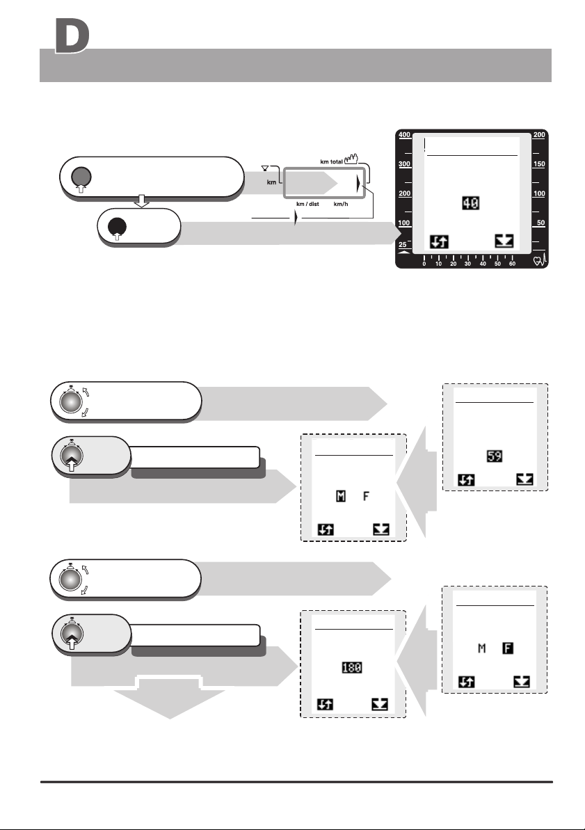
2.0 Data entry and alarm levels set up
If the alarm level of the pulse rate is reached or exceeded, the ergo_bike reduces automatically the braking
power in five watts per second increments until the actual pulse rate falls below the alarm level.
The entry of the age is mandatory for the display of the aerobic pulse zone for the user.
(see page 6)
The manual program must be selected before the entry of the data or alarm levels, otherwise
the entry of the pulse rate level will be skipped.
This also applies to all types of programs (watt, speed, manual, RPM, etc.), as the load
in watt will not exceed the value entered for the limit.
About the weight
About the personal performance evaluation
About the body fat content
About the sex and height
This data completes the profile stored by the computer for each user. And even the minimal difference in
capacities due to the sex has an important impact.
The weight has an important impact in the training for fitness improvement, and in the global physical activities.
The user should therefore enter this value consciously, in order for the training to be properly measured and
evaluated. The weight can be entered or adjusted daily (see page 56). Thus, the fitness evaluation function can
produce more precise data about the training results.
You should use a good body fat analyser, available commercially, to determine the body fat content value. The
measured values (between 0% and 55%) can be entered daily in the computer of the (see page 56).
The default value (DF) is set at 30%.
ergo_bike
About the Watt upper limit
About the pulse rate limit
Here the user is required to evaluate his or her own performance capacities. The user must grade his
performance according to the following scale 0 -1 - 2 - 3. Where grade 0means the user is a beginner and
grade 3means the user is a very well trained sportsman. (See also the information about your own
performance evaluation on page H3 in the chapter about the Coaching program).
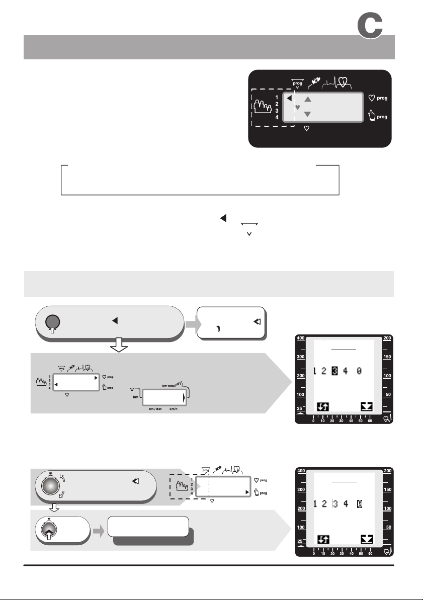
Setting up the personal data and alarm levels
Preparing for training

data user 1
hight
data user 1
sex
watt
data user 1
age
16
1.
0
2.
dat
reset
16
The value displayed for km total will be 0 km when setting up
a new device. Otherwise, the number of kilometres accumulated
for the respective user (1 to 4) will be displayed.
either accept the DF value 40
or modify the age
either accept the DF value F or
modify it
)))
1 x
press Arrow
!
window no. 6 displays
Window no. 4
press repeatedly,
until the km total arrow is
displayed in window no. 4
Window no. 6
Window no. 6
Window no. 6
2.1 Age entry
The devault setting is
40 years (DF)
Turn until the age
of the user (e.g. 40)
is correctly displayed
next setting / sex
1 x
press The setting is confirmed
and saved
Alarm value for the age 59 years
2.2 Sex entry
Turn until the sex
of the user is
correctly displayed
Alarm value / Sex F
next setting / height
2.3 height entry (see page 17)
Entry procedure tor
the personal data and alarm values
data user 1
age
data user 1
sex
Preparing for training
Personal settings Training
Window no. 6
1 x
press The setting is confirmed
and saved
Window no. 6
Table of contents
Other Daum electronic Exercise Bike manuals

Daum electronic
Daum electronic Premium 8 User manual

Daum electronic
Daum electronic Cardio 2002 PC User manual

Daum electronic
Daum electronic Fitness 3 User manual

Daum electronic
Daum electronic ergo_bike medical8 User manual

Daum electronic
Daum electronic ergo bike Premium 8i Series User manual

Daum electronic
Daum electronic 8008 TRS3 User manual

Daum electronic
Daum electronic Cardio pro User manual

Daum electronic
Daum electronic 8008 TRS User manual