David Clark U9921-GUV User manual
19541P-72 (05-11) 2011 DAVID CLARK COMPANY INCORPORATED
USER MANUAL
Universal Gateway
U9921-GUV(EU)
(P/N: 40994G-02)

19541P-72 (05-11) 1 of 9
C
Ca
au
ut
ti
io
on
ns
s
a
an
nd
d
W
Wa
ar
rn
ni
in
ng
gs
s
READ AND SAVE THESE INSTRUCTIONS. Follow the instructions in this installation
manual. These instructions must be followed to avoid damage to this product and
associated equipment. Product operation and reliability depends on proper usage.
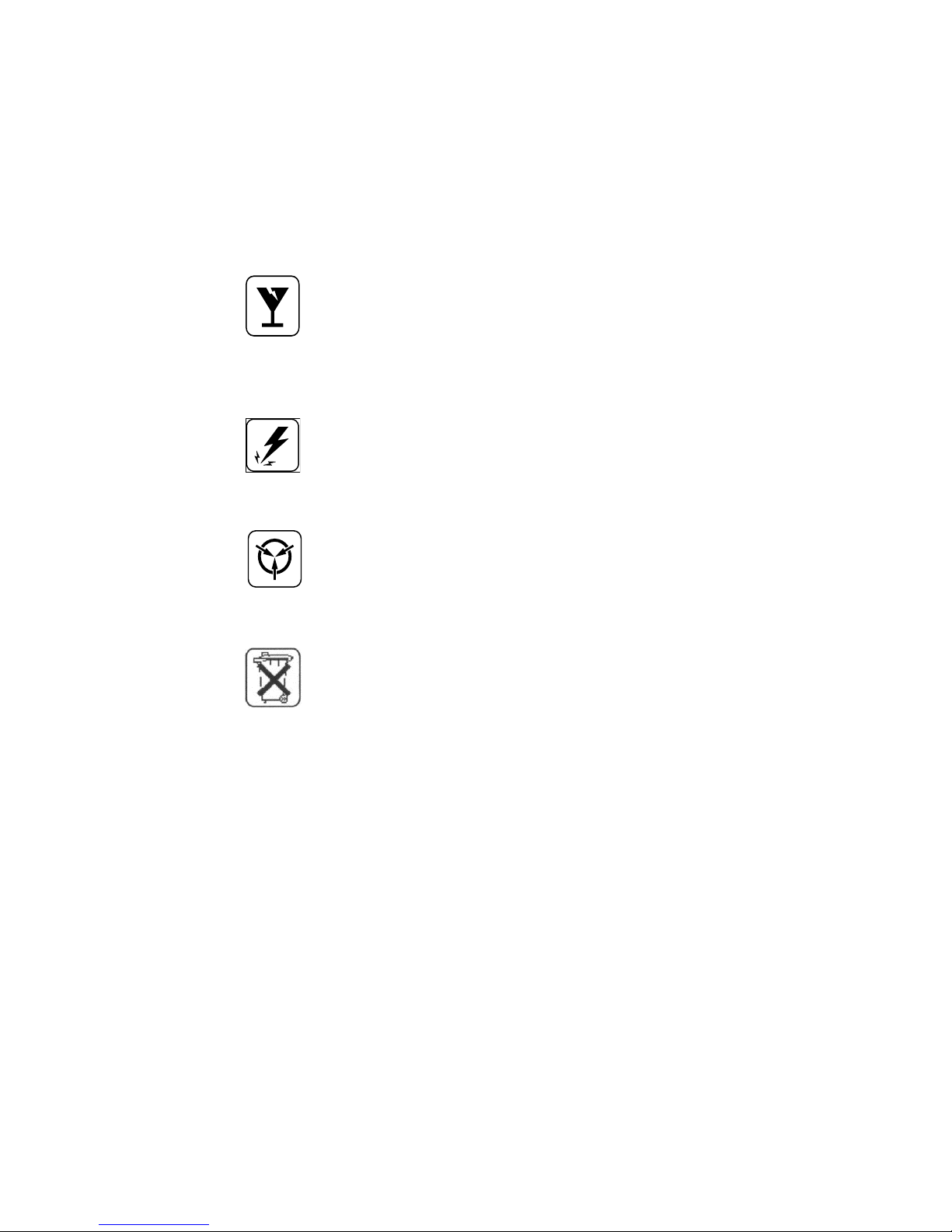
DO NOT INSTALL ANY DAVID CLARK COMPANY PRODUCT THAT
APPEARS DAMAGED. Upon unpacking your David Clark product,
inspect the contents for shipping damage. If damage is apparent,
immediately file a claim with the carrier and notify your David Clark
product supplier.
ELECTRICAL HAZARD - Disconnect electrical power when making any
internal adjustments or repairs. All repairs should be performed by a
representative or authorized agent of the David Clark Company.
STATIC HAZARD - Static electricity can damage components.
Therefore, be sure to ground yourself before opening or installing
components.
LI-POLYMER - This product is used with Li-Polymer batteries. Do not
incinerate, disassemble, short circuit, or expose the battery to high
temperatures. Battery must be disposed of properly in accordance
with local regulations.
19541P-72 (05-11) 2 of 9
O
Ov
ve
er
rv
vi
ie
ew
w
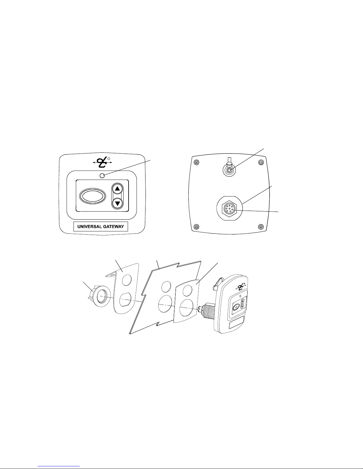
The U9921-GUV(EU) (40994G-02) Universal Gateway is a fixed-mounted wireless
communication device that, when used in conjunction with one or more U9910-BSW(EU)
(40992G-03) or U9912-BSW(EU) (40992G-04) Wireless Belt Stations, becomes part of a wireless
intercom system. The U9921-GUV provides communication for up to four users as well as an
interface to an existing wired intercom system. Up to four belt stations can be connected to one
gateway.
Status LED
Gasket
Bracket
Nut
Panel
Antenna
Connection
Threaded
Post
Interface
Connector
LINK VOL
R
Figure 1: Overview of Gateway

19541P-72 (05-11) 3 of 9
I
In
ns
st
ta
al
ll
la
at
ti
io
on
n
Intercom Interface
The U9921-GUV(EU) is designed to add wireless capability to an existing wired intercom.
Connection to the intercom is accomplished by connecting an interface cable to the interface
connector of the U9921-GUV(EU) (see Figure 1). The following list contains David Clark intercom
systems that have been tested to work with the U9921-GU(EU) and the required cable assembly.
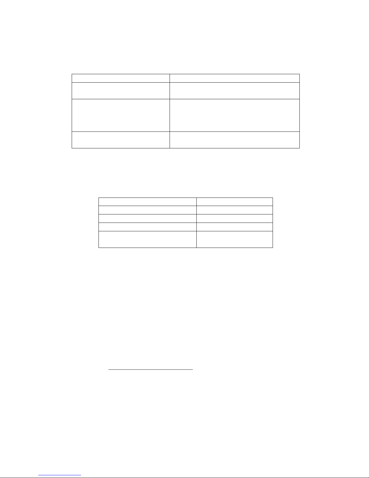
Table 1: Intercom Interface Cable Assemblies
David Clark Intercom Cable Assembly Required
U3800 Vehicular Intercom System C99-22MS (40935G-08)
U9800 Marine Intercom System C99-20CX (40935G-07)
U9500 Marine Intercom System C99-20LL (40935G-06)
U3400 Portable Intercom System
U3100 Modular Intercom System C99-20MS (40935G-05)
The U9921-GUV(EU) will detect the cable assemblies listed above and automatically make the
necessary audio level adjustments for the corresponding intercom.
Mounting
The U9921-GUV(EU) may be flush mounted or surface mounted using the included gasket, nut,
and bracket. See Figure 1 for mounting suggestions.
Note: Bracket (P/N: 41045G-01) optional. Not used for flush mount applications. Bracket
mounting configuration may be reversed for varying requirements (e.g., vehicle dash vs. ceiling-
mount.)
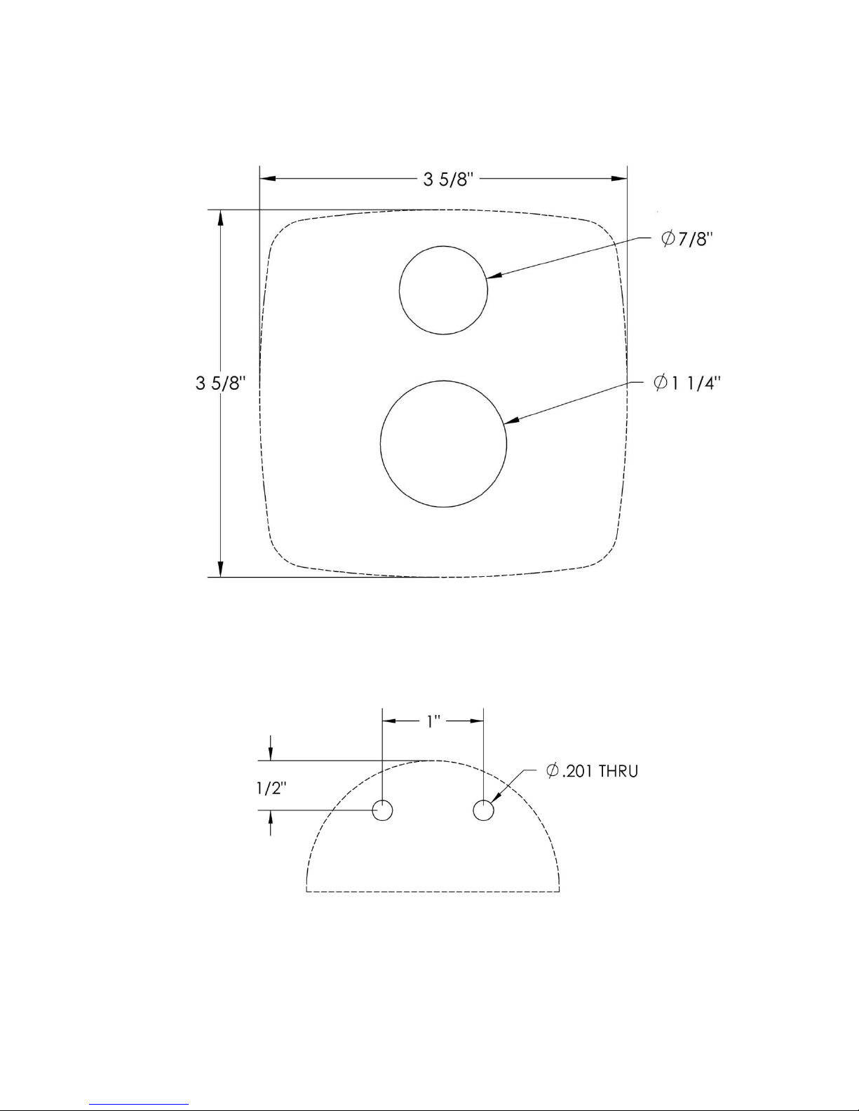
See Appendix A for Mounting Templates.
Antenna
The U9921-GUV(EU) has an internal antenna. An external antenna may not be necessary but the
antenna connector is provided for either the included whip antenna or an optional remote
antenna kit (P/N: 40688G-93 for mag-mount, 40688G-96 for permanent install).
Choose an open, clear location for the remote antenna and route the coaxial cable away from
any busy areas, preferably behind panels or in conduits.
This device has been designed to operate with the antennas listed below, and having a
maximum gain of 3 dB. Antennas not included in this list or having a gain greater than 3 dB are
strictly prohibited for use with this device. The required antenna impedance is 50 ohms.

19541P-72 (05-11) 4 of 9
Acceptable antennas for use with this product:
•Whip Antenna (P/N: 40688G-92)
•Remote Antenna Kit, Mag-Mount (P/N: 40688G-93)
•Remote Antenna Kit, Permanent (P/N: 40688G-96)
L
Li
in
nk
ki
in
ng
g
Before a belt station and a gateway can be connected, they must first be linked. As a security
measure, the close-link feature requires devices to be in proximity of between 1 to 3 ft (0.3 to
0.9m) in order to successfully link. This ensures that the units are not inadvertently linked with
other units on the premises.
Linking procedure:
1. Ensure units are within 1 to 3 ft (0.3 to 0.9m) of each other.
2. Simultaneously (within 1-2 sec) press and release the LINK button on the U9921-GUV(EU)
and the power button on the belt station to link with.
3. Amber LED’s will flash on both devices. A momentary red LED indicates a successful
close-link.
4. Upon successful link the U9921-GUV(EU) will attempt to establish a connection with the
belt station.
5. Upon successfully establishing connection the LED on the controller will flash a green
pattern corresponding to the number of belt stations connected.
Tip:
Once linked, the devices will not need to be linked again unless they are purged (see
Purging).
Each belt station is able to be linked to only one gateway at a time. A gateway can have up to six
belt stations linked and be connected to four of those six at one time.
S
St
ta
at
tu
us
s
I
In
nd
di
ic
ca
at
ti
io
on
ns
s
The front panel has a multi-color LED in the center which serves as a status indication for the
gateway. Table 1 below lists these states.

19541P-72 (05-11) 5 of 9
Table 2: LED Status Indications
LED Color Blink Rate Status
Red Solid Initializing/power up
Red Once Connection Dropped
Red Once Connection Established
Red Any Low battery (approx. 1 hr remaining)
Orange Slow Idle/Disconnected
Orange Fast Link/Connection in Progress
Orange Solid PTT asserted
Green Slow Connected (pattern indicates
number of belt stations connected)
O
Op
pe
er
ra
at
ti
io
on
n
Communication
All connected belt stations will be able to communicate with each other through the U9921-
GUV(EU) while in range (and per the VOX settings on a VOX belt station.) Additionally, all belt
station users will have communication over the intercom. If the intercom is so equipped,
pressing the PTT button on a VOX belt station will allow the user to transmit over the system’s
two-way radio. Pressing the PTT overrides the VOX setting on a VOX belt station. Multiple VOX
belt station users may PTT and thus speak over the two-way radio simultaneously. For more
information consult the user manual for the belt station.
Tip:
Wireless users who are not pressing PTT while another wireless user is pressing PTT
will not be heard on the wired intercom while the PTT remains pressed.
Intercom Level Adjustment
Audio levels can vary between intercoms, mainly due to the system level setting on the wired
intercom. To compensate for this, the U9921-GUV(EU) has the ability to adjust its receive level
from the intercom using the Vol keys (see Figure 1). Pressing these keys will increase or decrease
the audio level coming from the wired intercom into the gateway. Perform this adjustment to
obtain optimum performance.
Receive Level Adjustment Procedure
1. Connect at least one belt station to the U9921-GUV(EU) gateway and ensure
sidetone is present (see belt station User Manual).
2. Begin speaking and slowly and repeatedly press the Volume Up key on the U9921-
GUV(EU) gateway until you hear an echo of your own voice.
3. Continue speaking and press the Volume Down key until the echo stops.
4. You may wish to verify communication with someone hard-wired to the intercom.

19541P-72 (05-11) 6 of 9
Range
The range of a belt station and a gateway can be up to 300 ft (100m). If you are in an
environment with metal or concrete walls, this range could be reduced. If the belt station enters
into a "fringe" reception area, a brief sequence of three beeps will be heard in the headset. This
is to serve as a warning of a possible disconnection if conditions are not improved. When
possible, the user should attempt to regain line-of-sight contact with the controller. When the
belt station travels out of range of the gateway, a voice alert will indicate that the connection has
been lost. To reconnect, simply move back into range and connection with the gateway will
automatically be reestablished, also noted by a voice alert.
P
Pu
ur
rg
gi
in
ng
g
In some circumstances it may be necessary to “purge” the U9921-GUV(EU) of some of its linked
belt stations. Typically purging is not necessary unless there are multiple gateways in the same
vicinity and you wish to remove a belt station from this gateway and link to a different gateway.
A gateway can link up to six belt stations where a belt station can be linked to only one gateway
at a time.
Smart Purge
A smart purge is the purge method employed for the U9921-GUV(EU), in which only unwanted
links are removed from the gateway. When this procedure is complete, only belt stations that
are connected to the gateway remain linked. All other belt station links will have been removed
(see the belt station User Manual for the individual belt station purging procedure when
remaining link purging may be necessary.)
Smart Purge procedure
1. Ensure the gateway is powered on and functioning.
2. Disconnect all belt stations to be purged (power off the belt stations).
3. Verify the number of green LED flashes on the gateway matches the number of
belt stations to be kept linked.
4. Press and hold LINK button on the gateway for 30 seconds until LED quickly
flashes red.
5. Release LINK button.
19541P-72 (05-11) 7 of 9
T
Tr
ro
ou
ub
bl
le
es
sh
ho
oo
ot
ti
in
ng
g
Table 3: Troubleshooting
Problem Solution
Gateway will not turn on Ensure correct interface cable is being used
(Table 2)
Cannot link a belt station Review Registration procedure
Ensure units are within 1 to 3ft (0.3 to 0.9m)
of each other
Try a Smart Purge
Cannot speak over two-way radio PTT not pressed
Two-way radio not installed to system
R
Re
ep
pl
la
ac
ce
em
me
en
nt
t
P
Pa
ar
rt
ts
s
•Interface cable assemblies:
David Clark Intercom Cable Assembly Required
U3800 Vehicular Intercom System C99-22MS (40935G-08)
U9800 Marine Intercom System C99-20CX (40935G-07)
U9500 Marine Intercom System C99-20LL (40935G-06)
U3400 Portable Intercom System
U3100 Modular Intercom System C99-20MS (40935G-05)
•Whip Antenna (P/N: 40688G-92)
•Remote Antenna Kit, Mag-Mount (P/N: 40688G-93)
•Remote Antenna Kit, Permanent (P/N: 40688G-96)
•Mounting Bracket Kit (P/N: 41045G-01)
C
Ca
ar
re
e
a
an
nd
d
M
Ma
ai
in
nt
te
en
na
an
nc
ce
e
The U9921-GUV(EU) is not user serviceable. Do not attempt to open the enclosure. If this
product requires service, please contact the David Clark Customer Service department:
•Phone: 800.298.6235
•E-Mail: serviceWWW@DavidClark.com
•By Mail: Customer Service
David Clark Company
360 Franklin Street
Worcester, MA 01604

19541P-72 (05-11) 8 of 9
If necessary, the U9921-GUV(EU) may be wiped down with a mild soap and water mixture.
Although it is a sealed device designed to withstand submersion in water to 1 meter, do not
unnecessarily submerse this product in water.
Avoid storage of this product in direct sunlight or high temperature environments.
S
Sp
pe
ec
ci
if
fi
ic
ca
at
ti
io
on
ns
s
Frequency Range 1880 MHz - 1900 MHz (EU)
Average RF Power Output 10 mW (250 mW peak) (EU)
Range 300 ft (100m) line-of-sight (nominal)
Operating Temperature -14°F to 113°F (-10°C to +45°C)
Storage Temperature -4°F to 140°F (-20°C to +60°C)
Power Requirements 8 to 25VDC
U
Un
na
au
ut
th
ho
or
ri
iz
ze
ed
d
C
Ch
ha
an
ng
ge
es
s
Changes or modifications not expressly approved by David Clark Company, Inc. could void the
users’ authority to operate the equipment.
U
Us
sa
ag
ge
e
R
Re
es
st
tr
ri
ic
ct
ti
io
on
ns
s
Due to the DECT frequencies used, this product is licensed for operation only in the European
Union countries.
19541P-72 (05-11) 9 of 9
Appendix A: Mounting Templates
Figure A1: Flush Mount
Figure A2: Bracket Mount – Optional (P/N: 41045G-01)
Other manuals for U9921-GUV
2
This manual suits for next models
1
Table of contents
Other David Clark Gateway manuals

David Clark
David Clark 3800 User manual

David Clark
David Clark U9921-GUV User manual

David Clark
David Clark 3800 U9922-G38 User manual

David Clark
David Clark U9120-W4 User manual

David Clark
David Clark U9922-G38 User manual

David Clark
David Clark 44002G-01 User manual

David Clark
David Clark U9921-GUV User manual

David Clark
David Clark ConneX CREW User manual


