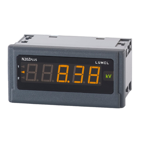
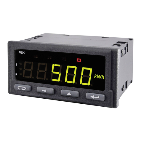
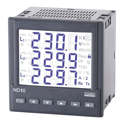
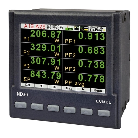
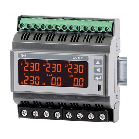
Lumel N10A User manual

1
POWER NETWORK
PARAMETER
ANALYSER
N10A
SERVICE MANUAL

2

3
POWER NETWORK PARAMETER ANALYSER - N10A
SERVICE MANUAL
CONTENTS
1. APPLICATION................................................................................. 5
2. METER SET.................................................................................... 6
3. INSTALLATION............................................................................... 6
3.1. FITTING................................................................................... 6
3.2. EXTERNAL CONNECTION DIAGRAMS ................................ 8
4. PROGRAMMING .......................................................................... 13
4.1. FACEPLATE DESCRIPTION.................................................. 13
4.2. N10A OPERATING MODES................................................... 14
4.2.1 MEASURING MODE...................................................... 15
4.2.1.1. Measurement of voltage and current harmonics........ 16
4.2.2. TIME SETTING MODE - t ............................................. 17
4.2.3. PARAMETER CONFIGURATION MODE - S................ 17
4.2.4. ALARM CONFIGURATION MODE - A .......................... 19
4.2.5. PAGE CONFIGURATION MODE - P ........................... 19
5. ERROR CODES............................................................................ 25
6. TECHNICAL DATA ....................................................................... 25
7. ORDERING CODES ..................................................................... 29
8. MAINTENANCE AND WARRANTY.............................................. 30
March 2007 - KZ 1268/06

4

5
1. APPLICATIONS
The N10A type meter is a programmable digital instrument destined to measure
parameters in three-phase three-wire or four-wire power networks, in symmetric
and asymmetric systems. The N10A meter is a version of the N10 meter, in which
3 bi-directional analog outputs have been added for customers’ needs.
The N10A meter enables the display of measured and calculated quantities (196 in
all), the digital transmission of their values and the conversion into three bi-directional
analog output signals.
Internal current and voltage transformers ensure the galvanic separation of mea-
sured channels.
The N10A meter ensure the measurement of: RMS voltage and current, active, re-
active and apparent power, active reactive and apparent energy, power coefficients,
frequency, 15-minute average active power.
Voltages and currents are multiplied by voltage and current ratios of measuring
transducers what is taking in consideration in calculations and indications of power
and energy. The meter shows also the real time.
The RS-485 interface enables the communication with the master system.
Other communication protocols can be realised through the external converter, e.g.
the PD7 type with MODBUS/PROFIBUS.
One of the important feature is the possibility to perform the programmed selection
of 3 quantities which are converted into bi-directional current signals on 3 analog
outputs of the meter.
The relay output can serve to signal the overflow of the chosen quantity threshold.
Measurements are carried out by the sampling method of the voltage and current
signal.
The meter is adapted to be fixed in a panel by means of holders.
Differences between N10 and N10A meters
N10 N10A
Analog outputs 1 output 0...20 mA (4...20 mA)
accuracy 0.5%
3 outputs ± 5 mA (0...5 mA)
accuracy 0.2 %
Relay outputs
Impulse passive
outputs
Impulse passive
input
3 relays 1 relay
none1 output
1 input none

6
2. METER SET
The set includes:
- N10A type meter 1 pc.
- service manual 1 pc.
- warranty card 1 pc.
- holders to fix into a pannel 4 pcs.
Additionally for the execution with interface:
- service manual of the serial interface 1 pc.
- lead of the RS-485 interface 1 pc.
- matching resistor 1 pc.
- diskette for the WIZPAR program 1 pc.
3. INSTALLATION
3.1. Fitting way
The meter is adapted to be mounted by means of holders according fig.1.
The meter housing is made of a sell-extinguishing plastics.
Housing dimensions are 144x144x77mm. At the rear side of the meter there are
terminal strips which enable the connection of 2.5 mm2external leads.

7
Fig.1 Overall dimensions and fitting way of the N10A meter.

8
3.2. External connection diagrams
Direct measurement in a 3-phase network
Half-intermediate measurement in a 3-phase network

9
Fig. 2. Meter connection diagrams in a three-phase network
Intermediate measurement using 2-current transformers and 2 or 3 voltage trans-
formers in a 3-phase network

10
Direct measurement in a 4-wire network
Half-intermediate measurement in a 4-wire network

11
Fig. 3. Meter connection diagrams in a four-wire network
Intermediate measurement using 2-current transformers and 2 or 3 voltage trans-
formers in a 4-wire network

12
NOTICE:
To make the IBM PC - N10A meter (RS-485) connection it is recommended to use a double-wire
twisted conductor in a shield. The shield should be connected to the earth in one point. The shield
is necessary when the environment is very perturbed.
Fig. 4. Connecting way of N10A meters with an RS-485 interface.

13
4. PROGRAMMING
4.1. Faceplate description
The N10A meter has 6 keys, four 5-digits display sections, illuminated symbols
and parameter units. Values of measured parameters are shown on active pages
selected by successive pressures of the key.
A page consists of 4 optional quantities chosen from the table 5 and displayed
simultaneously on the meter.
The page definition is described in the configuration mode P.
Fig. 5. View of the N10A meter faceplate

14
Table 1.
1 acceptance key
2 displacement key
3 increase key
4 decrease key
5 displacement key
6 resignation key
The assignment of individual keys
is as follows:
Key
It is destined to accept the introduced
value during the programmation.
It enables the change of pages in the
measuring mode.
Keys
They are destined to change the digit
value on the decimal position during the
programmation.
Keys
They allow the cursor displacement to successive decimal positions during the pro-
grammation and enable the change of display luminosity in the SETUP procedure.
Key
This key enables in anytime the resignation of carried out operations.
It cancels alarms in measuring mode.
4.2. N10A operating modes
The N10A meter has 5 operating modes represented on the table 2.
Table 2
MODE
NAME CALLING
OUT SYMBOL INPUT OUTPUT
Measuring default Through entry to another mode
Time setting tin SETUP
procedure , or after the last parameter
Page
configuration Pin SETUP
procedure , or after the last page
Parameter
configuration S
Alarm
configuration
and analog
outputs
A
, or after the last parameter
in SETUP
procedure
in SETUP
procedure
They enable the display of suitably minimal and maximal values in the measure-
ment mode.

15
After its switching on, the meter carries out tests informing by a message:
After tests carrying out, the meter enters into the measuring mode and displays the
page positioned before switching off.
The entry into another mode is made in the SETUP procedure. In order to enter
in the SETUP procedure one should press two keys:
during ca 3 seconds, until the audible signal will be switched off.
where: r.1.01 - No of the actual
program version
Choose by means of keys the appropriate mode. The active mode
t, P, S or A is signalled by the flashing of the suitable symbol. Accept the chosen
mode by the key.
The return from other modes into the measuring mode is carried out by means of
the or key:
- after the last parameter (in t, S and A modes),
- after the last page (in the P mode).
4.2.1. Measuring mode
Values of different quantities are displayed acc. programmed pages by the manu-
facturer or configurated by the user in the Pmode.
The change of page is realized by pressing the Key. The sequence of dis-
played pages is proceeded acc. the table formed in the Pmode.
The monitoring of maximal or minimal values is realized when pressing respectively
the or key. The cancellation of maximal or minimal values is realized
when pressing the key during the monitoring of these values, i.e. at first the

16
or key must be pressed and after the key.
Alarm is active if it was allocated. One must notice that the alarm do not need to
be related to quantities displayed on the page, because a change of page would
cause an action on the two-state output.
4.2.1.1. Measurement of voltages and current harmonics
The selection of harmonics is made by pressing keys for reviewing
current harmonics, or by keys for reviewing voltage harmonics.
The selected U1,U2,U3 or I1,I2, I3 quantity is signalled by the flashing of the suitable
digit. One must choose by the or key the required quantity and press
the key. The following quantities will be displayed:
Where: w-n - chosen quantity, e.g. U-1
n-n - harmonic number
xxx.x - value of the n-th harmonic
The harmonic number up to the 25th harmonic can be changed by means of
or keys. The active position is signalled by the cursor. One can return to
display the selection of reviewed harmonics by pressing the key. A successive
pressure of the key means the return to the measuring mode.
For wrong THD indications, successive harmonic values will not be displayed.
NOTICE:
Indications appear when the parameter 15 will be switch on in the SETUP mode,
i.e. the selection of the harmonic measurement and the assumptions concerning
their measurements will be fulfilled.

17
4.2.2. Setting time mode - t
After the entry into the SETUP procedure one must choose the mode t by pressing
the or key and the key. Following values will be displayed:
By means of keys required values can be set, i.e. the
position of the decimal digit can be choosen by the or key, the digit
value by the or key. The cursor signals the active position. The set
value can be accepted by the key or cancelled by the key and comes
back into the measuring mode.
causes the setting on the successive parameter.
after dd (day), causes the transition to hours and minutes settings.
Where: yyyy - year
mm - month
dd - day
The setting of hours and minutes is similar to the setting of the year, month and day.
after min (minutes), causes the memorization of set values and the exit
from the mode t. The second counter is not be set but it is zeroed when accepting
minutes. This means that in order to obtain an accurate timer setting one must wait
till a full minute and then press the key (ENTER).
4.2.3. Parameter configuration mode - S
This mode is destined to set meter parameters, input and output signal values. The
entry into the parameter configuration mode is protected by the access code if an
access code different from zero had been introduced.
Where: hh - hours
mm - mminutes
ss - secondes

18
In the case of 0000 code, password inquiry is omitted. If the access code is different
from zero, there is the possibility of parameter reviewing, but changes are locked.
Values are set in this mode acc. to the table 3.
Table 3
Manu-
facturer’s
values
Item
Parameter name Designa-
tion Range Notice/
description
1 Introduction of access code SECU 0000... 9999 0000 - without code 0000
2 Setting of meter parameters
by the manufacturer rESt Y/n
Ratio of current transformer tr_I 1... 20000 13
4
5
6
7
8
9
10
12
13
14
1
1
19200
n
Ratio of voltage transformer tr_U 1... 4000
Quantity on the continuous
output Ao_n 0... 34 Quantity code acc.
table 5
Cancellation of the active
energy counter
EnP0 Y/n n
Cancellation of the reactive
energy counter
Enq0 Y/n n
Cancellation of the apparent
energy counter
EnS0 Y/n n
Cancellation of the
15-minu-tes active power
PAV (max. and min. Value)
PA_0 Y/n n
15,30,60 min.Averaging time of PAV power PA_t 15
11 synchronization of the PAV
power averaging to the
virtual timer
PA_S Y/n Y
Meter address in the system Adr 1... 247 1
300,600,..,
19200
Speed of the serial interface bAUd
0, 1, ...,6Interface working mode trYb 0 -switched off interface
1 - MODBUS ASCII 8N1
2 - MODBUS ASCII 7E1
3 - MODBUS ASCII 7O1
4 - MODBUS RTU 8N2
5 - MODBUS RTU 8E1
6 - MODBUS RTU 8O1
0
15 Selection of the harmonic
measurement
Har 0.1 0
16 Change of the access code 0000... 9999 0000

19
In parameters 5, 14 the range 0 means that the appropriate output, or interface
switched off.
Notations:
N - lack of parity (no parity),
E - bit checking the even parity,
O - bit checking the odd parity.
The entry into the procedure causes the setting on the parameter 1 or 2 if the access
code is equal 0000. We adjust required values by means of
keys, i.e. one can choose the position of the decimal digit by pressing the
or key , the digit value by pressing the or key. The
active position is signalled by the cursor.
One can accept the established value by pressing the key or cancel it by
pressing the key and come back to the measuring mode.
causes the setting on the successive parameter.
after the last parameter, causes the memorization of setting values and the
exit from the mode S.
Notice:
PA_S=Y means that the average power PAV will be brought up to date every
15, 30, or 60 minutes synchronized with the internal virtual timer.
PA_S=n means that the average power will be calculated for the last 15, 30,
or 60 minutes and brought up to date every 1 second, so-called „moving
window”.
4.2.4. Alarm configuration mode - A
This mode serves to:
- attribute the quantity to alarms,
- Set the thresholds setting of alarm switching on and off (also the direction of
alarm action).
- set the latency of alarm operation,
- assign any quantity of the group of 34 parameters (acc. to table 5) of continuous
output current signal,
- set the changing window of the input signal.

20
Table 4
Manu-
facturer’s
values
Item
Parameter name Designa-
tion Range Notice/
description
1 A1_n 0, 1... 34 2
4
5
6
7
8
10
11
12
99
Quantity code acc.
table 5
ALdt 0
Ao_1 0 (off)
AoL1 - 100
9
13
Two-state output 1 - quantity
2 A1on 0... 120 [%]
Two-state output 1 - switch
on value
101
3 Two-state output 1 - switch
on value
A1oF 0... 120 [%]
Delay of alarm
switching on
0... 100 secDelay in the alarm operation
Quantity on the continuous
output nr 1
0, 1... 34 Quantity code acc.
table 5
Lower value of the input
range
-120...0...120
Upper value of the input
range
AoH1 -120...0...120
Ao_2 0 (off)
Quantity on the continuous
output nr 2
0, 1... 34 Quantity code acc.
table 5
AoL2 - 100
Lower value of the input
range
-120...0...120
Upper value of the input
range
AoH2 -120...0...120
Ao_3 0 (off)
Quantity on the continuous
output nr 3
0, 1... 34 Quantity code acc.
table 5
AoL3 - 100
Lower value of the input
range
-120...0...120
Upper value of the input
range
AoH3 -120...0...120
The entry into the mode of alarm setting is not protected by the access code.
Alarms are active if they were attributed, i.e. if a measured quantity different than
zero (table 5) has been attributed to them. One must notice that alarms concern
chosen quantities in the basic configuration mode S and they are not related
with quantities displayed on the page. If the quantity value related to the alarm
exceeds the declared threshold, the two-state output corresponding to this alarm
will be switched on (relay) and the symbol A1 will be lighted. If the quantity value
decreases below the alarm threshold, the two-state output is switched off, but the
A1 signalling remains until the time of its cancellation by means of the ESC key.
Table of contents
Other Lumel Measuring Instrument manuals
Popular Measuring Instrument manuals by other brands

Elma Instruments
Elma Instruments Elma 9200BT manual

Hioki
Hioki CT9691 installation manual

Exotek Instruments
Exotek Instruments MC-60CPA user manual

PCE Americas
PCE Americas PCE-WM 1 manual

Dwyer Instruments
Dwyer Instruments RVM Specifications-installation and operating instructions

ELMETRON
ELMETRON CX-461 user manual

Airmar
Airmar WeatherStation 200WXRS Owner's guide & installation instructions

Qu-Bit Electronix
Qu-Bit Electronix EON manual

Velleman
Velleman DVM8080 user manual

KROHNE
KROHNE OPTIMASS 1000 Series Guidelines for use

Simpson
Simpson S664 Operation manual

Cleveland Controls
Cleveland Controls 6650 instruction manual