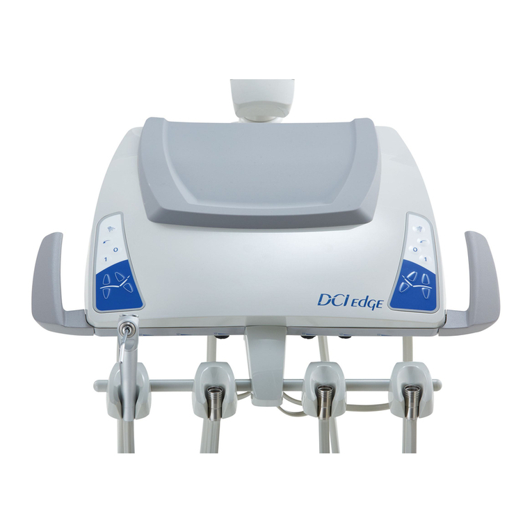
DCI Edge ORTHODONTIC CHAIR User manual

ORTHODONTIC CHAIR
Installation Instructions

2
OVERVIEW
2
ORTHODONTIC CHAIR
Installation Instructions
71.40"
63.85"
22.75"
21.65"

3
INTRODUCTION
3
ORTHODONTIC CHAIR
Installation Instructions
System Overview
Introduction
General Safety
Preparations
Installation
Troubleshooting
SYMBOLS
The following symbols may be used throughout this product manual:
CAUTION: General Caution. Failure to carefully follow
the described procedure may result in damage to the
equipment.
ELECTRICAL HAZARD: Risk of electrical shock pres-
ent. Ensure that power is disconnected before attempt-
ing this procedure.
TABLE OF CONTENTS
2
3
4
5
6
15
WARNING: Failure to carefully follow the described
procedure may result in damage to the equipment, the
operatory, and/or the operator.
NOTE: Take note of additional important information.
Not a warning or caution.
Manufacturer
Manufacturing date
Protective Earth (ground)
Waste Electrical and Electronic Equipment
Type B Equipment (Protected against electrical shock)
Alternating Current
Conforms to applicable European Directives
(Essential Requirements)
Electrical Testing Lab
Advisable to consult
accompanying documents
Power OFF Power ON
Refer to instruction
manual/booklet
Home Position
Backrest Movement Position

4
GENERAL SAFETY
4
ORTHODONTIC CHAIR
Installation Instructions
WARNINGS & CAUTIONS
WARNING: This product must be
disinfected before use.
CAUTION: Only authorized service
technicians should attempt to service this
equipment. Use of other than authorized
technicians will void the warranty
CAUTION: Use a licensed electrician for
all wiring.
WARNING: To avoid risk of electric
shock, this equipment must be connected
only to supply mains with protective
ground.
WARNING: Modication of this
equipment is not allowed.
WARNING: Failure to disinfect this
device between patients could expose the
user and patient to cross contamination
and bio burden/biocontamination.
WARNING: Power cords and their
associated parts cannot be substituted
without increase risk of shock or re.
Use authorized replacement parts only.
Power cords must be installed by qualied
personnel. Ensure all service loops, strain
reliefs and cord guards are in place and
that line, neutral and ground wires are
secured.
WARNING: Patient weight capacity is
350lbs. Do not exceed this limit. Doing so
may cause personal injury and/or damage
to the chair.
WARNING: To avoid possible injury and/
or damage to the chair, do not apply full
body weight on the headrest, backrest,
toeboard and armrest. Doing so may
cause the chair to tip.
WARNING: To isolate from mains power,
unplug the cord. Make sure to leave the
mains cord accessible.
WARNING: Do not connect extension
cords or power strips to the electrical
receptacles.
This product is intended for use by trained dental/
orthodontic professionals only.
WARNING: Do not sit on the backrest
or the toe end of the seat. These sec-
tions are not designed to support the full
weight of patient.
WARNING: Do not allow children
unsupervised access to the orthodontic
chair and auxiliary equipment.

5
PREPARATIONS
5
ORTHODONTIC CHAIR
Installation Instructions
UNPACKING
Preassembly Check: Open shipping cartons carefully and check to see that all parts are received and have not been
damaged during shipping.
Unpacking Chair: Carefully remove two (2) fasteners securing chair to pallet using nut driver supplied with order. Slide
chair from pallet to proper moving equipment and secure to move chair to nal installation location.
Take care when using any sharp objects or tools to avoid damage to upholstery or painted parts.
Complete chair: Chair and base assembly with upholstered headrest
Three (3) anchors (used to secure to oor)
Accessories Options (i.e., Arms, Light post, etc.)
Owner’s / Operator’s manual (Note: Accessories may be packaged separately)
CONTENTS
CAUTION: Chair should be lifted from below main seat frame. Do not at any time move chair by lifting
on back or seat upholstery or optional armrests. Use proper lifting techniques to avoid personal injury.

6
INSTALLATION
6
ORTHODONTIC CHAIR
Installation Instructions
FLOOR DRILLING
Location: Full size templates are available upon request for laying out location of chair and utilities (if required)
prior to actual installation.
CAUTION:
Base must be anchored to oor. Failure to do so may result in serious bodily injury
to operator and/or patient and could cause unwarranted product damage. Chairs not properly
anchored do not meet warranty requirements.
CAUTION:
To prevent possible injury or damage, do not drill through carpeting. Cut away carpeting
at anchor hole locations.
258 mm
240 mm
FRONT
CAUTION:
Before drilling into the oor, be sure to locate all utilities that may already be routed in
the oor to ensure that you can safely drill.
For concrete oors, drill 1/2"holes to approximately 2 1/2" deep on the oor according to the below
dimensions.
For wood oors, pre-drill holes sized for 1/2"lag bolts 2 1/2"deep.

7
INSTALLATION
7
ORTHODONTIC CHAIR
Installation Instructions
Hammer in 3 anchors to the 1/2” drilled holes.
Using 9/16” wrench, assemble washers and nuts and tighten to the oor.
CONCRETE FLOOR INSTALL
The below instructions are for installing onto a concrete oor. To install into a wood oor, skip to the next page.
Next, remove nuts and washers with the 9/16” wrench.

8
INSTALLATION
CHAIR MOUNTING
8
ORTHODONTIC CHAIR
Installation Instructions
For concrete oors: Align the chair to the oor anchors or pre-drilled holes and reassemble the
washers and nuts until snug.
For wood oors: Align the chair to the pre-drilled holes and assemble the lag screws and washers until
snug.

9
INSTALLATION
9
ORTHODONTIC CHAIR
Installation Instructions
COVER INSTALLATION
1Place Cover on Base Plate and make
electrical connections.
3
Re-engage the hook features of the foot
pad to the inside of the cutout in the
cover to complete the assembly.
2
Slide cover into place. Fold back the
rubber foot pad to expose the cutout
areas below, and add 2 10-32"screws to
secure the cover to the base plate using a
1/8"hex key.

10
INSTALLATION
HEIGHT ADJUSTMENT
10
ORTHODONTIC CHAIR
Installation Instructions
Access 2 bolts from
above as shown
here using a 9/16"
socket drive.
Adjust height by removing or adding 2 spacers between the post and the upper seat assembly.
Access 2 bolts from below as shown here
using a 3/16"hex key.
Disconnect 2 cable
harnesses here.
Remove the upper chair assembly from the post and remove or add spacers to the desired height.
4 set screws
(PN 59251)

11
INSTALLATION
11
ORTHODONTIC CHAIR
Installation Instructions
NO SPACERS
ONE SET OF SPACERS
TWO SETS OF SPACERS
Seat height: 20”
Bolt Part Number: 49068
Seat height: 21.5”
Bolt Part Number: 49064, 49038
Spacer Part Number: 41061
Seat height: 23”
Bolt Part Number: 49066, 49067
Spacer Part Number: 41061
Reassemble the upper portion of the chair using the bolts provided according to the length required as shown below.

12
INSTALLATION
12
ORTHODONTIC CHAIR
Installation Instructions
APPLY SEAT UPHOLSTERY
Position the seat squarely on the chair frame and push the seat toward the backrest to engage the 2 hooks
under the back ange of the frame. Lower the seat and install the 2 screws and split washers at the front
to lock the seat in place.

13
13
ORTHODONTIC CHAIR
Installation Instructions
INSTALL BACK UPHOLSERY
Engage the hooks on the back of the backrest upholstery to the horizontal bars in the back frame.
Slide the upholsery downward until it stops against the bars.
INSTALLATION
INSTALL HEADREST
Slide the headrest into the back frame assembly as shown.

14
14
ORTHODONTIC CHAIR
Installation Instructions
POWER CORD
Attach the power cord to the AC receptacle located on the side of the cover. Lower the wire clip
over the power cord to secure the connection.
INSTALLATION

15
15
ORTHODONTIC CHAIR
Installation Instructions
TROUBLESHOOTING
Symptoms: Appropriate Action:
Chair will not operate Check the main ON/OFF switch to ensure it is in the ON position.
Chair will not operate Check the A/C outlet that the chair is plugged into to ensure that there is power
going to the chair. Also check the building’s circuit breakers if no power is available at
the A/C outlet.
Main On/Off switch
(Cl) is “ON”
Motors will not work
1. Check to make sure that the round cable plug at the end of the motor cable is
pushed all the way into the Controller box located under the seat.
2. Check the cables connected between the Switch Interface Circuit and the
Controller (refer to Base Parts List) and assure they are completely engaged.
Noisy motor(s) Damaged gears - call for service.

305 N. Springbrook Road
Newberg, OR 97132, USA
PN 40040, Rev. B, 2018-06-28 www.dcionline.com
800-624-2793
Table of contents
Other DCI Edge Dental Equipment manuals
Popular Dental Equipment manuals by other brands
3M ESPE
3M ESPE Elipar DeepCure-S operating instructions
Ivoclar Vivadent
Ivoclar Vivadent Programat EP 5000 operating instructions

DentalEZ
DentalEZ StarDental 430 SWL Flex instruction manual
Aseptico
Aseptico AEU-6000-70V Operation and maintenance instruction manual

GNATUS
GNATUS Jet Hand I owner's manual
Patterson
Patterson 043-2005 BB-Y Operation manual
