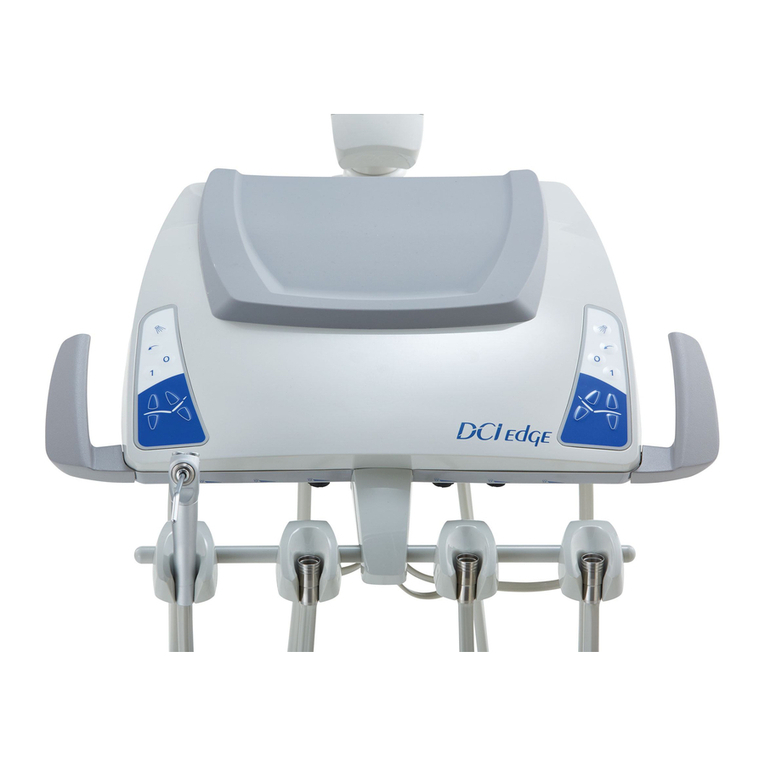
DCI Edge SERIES 5 User manual

SERIES 5 DENTAL CHAIR
Installation Instructions

OVERVIEW
2
SERIES 5 DENTAL CHAIR
Installation Instructions

INTRODUCTION
3
SERIES 5 DENTAL CHAIR
Installation Instructions
Overview
Introduction
Setup
Dimensional Layout
Chair Preparation
Upholstery Installation
Optional Quick Connect Box
Adjusting Soft Limits
Hydraulic System
Electrical
Diagnostic Codes
BEFORE YOU BEGIN
SYMBOLS USED IN THIS MANUAL
Study the chair overview in this booklet and layout dimensions from
the owner’s manual. Make sure the planned location will have the
necessary space available for installation, including room for travel of
the chair’s base and backrest.
Locate all documentation supplied with the package. Manuals and
installation sheets may be found in one or more boxes accompanying
their respective components. Set aside the owner’s manual for the
end user to review.
The following symbols may be used throughout this product manual:
WARNING: Failure to carefully follow the described
procedure may result in damage to the equipment or the
operator.
ELECTRICAL HAZARD: Risk of electrical shock pres-
ent. Ensure that power is disconnected before attempt-
ing procedure.
TABLE OF CONTENTS
2
3
4
5
6
7
8
9
10
11
12
CAUTION: Failure to carefully follow the described
procedure may result in damage to the equipment.
NOTE: Take note of additional important information.
Not a warning or caution.
Regulatory information is delivered with
DCI Edge dental equipment as mandated
by agency requirements and can be found
in the accompanying Instructions for Use
for this device.
REGULATORY INFORMATION

SETUP
TOOLS NEEDED FOR INSTALLATION
• Scissors or utility knife
• Allen wrench set
• Socket wrench set
INCLUDED HARDWARE AND COMPONENTS
WARNING: To prevent injury, use an as-
sistant to help safely position the chair in the
operatory.
PLACE THE CHAIR IN LOCATION
1
Remove the shipping straps and open the crate.
2Remove the 3/8” bolts holding the chair to the
wood pallet.
3
Carefully remove the chair from the pallet and position it in the proper location for installation. Refer to dimensional
information on the next page for guidance in positioning the chair.
4Check that the chair rests at and level on the oor and that it does not rock due to uneven areas on the oor.
Use shims to eliminate gaps if the surface is uneven.
• Power Switch Cover
4
SERIES 5 DENTAL CHAIR
Installation Instructions

DIMENSIONAL LAYOUT
5
SERIES 5 DENTAL CHAIR
Installation Instructions
CHAIR AND UNIT DIMENSIONS
77.8
62.1
15.0
8.0
88.0
7.3
5°
4.0
90.5
94.6
7.4
102.0
SHOWS POSITION OF POLE WHEN
CHAIR IS RAISED TO FULL HEIGHT
AIR
MASTER
VALVE
AIR
WATER
ELECTRICAL
VACUUM
DRAIN
MASTER
VALVE
WATER
2”
5”
1”
2”
17.2”
4”
16”
8” ACCESSORY
CHASE
3”
1”
JUNCTION BOX LAYOUT

CHAIR PREPARATION
SHIPPING BOLT
1
Rotate the backrest into position by aligning
the backrest bottom holes to the holes in the
link bar which extends from the upper hydraulic
assembly.
2
Loosen the set screw which secures
the steel
cross pin. Align the holes of the backrest and
the back link and re-insert the cross pin. If neces-
sary, use a rubber mallet to drive the pin until it has
fully engaged both parts.
3
Tighten the set screw on the backrest link
against the pin to prohibit its movement.
Remove the shipping bolt by unscrewing from
above the seat pan casting using a 3/8” wrench.
Once unscrewed, removed the bolt and related
hardware from the assembly.
Power Switch Cover: Install the power switch
cover into the opening around the power switch
by snapping it rmly into place.
Foot Switch: Unpack the foot switch and set in
position for use.
POWER SWITCH COVER
FOOT SWITCH
BACKREST FOOTPAD
PRESET POSITION “1”
PRESET POSITION “0”
RETURN TO LAST POSITION
6
SERIES 5 DENTAL CHAIR
Installation Instructions

UPHOLSTERY INSTALLATION
7
SERIES 5 DENTAL CHAIR
Installation Instructions
SEAT UPHOLSTERY
1
Center and place the seat upholstery on the seat
plate so that the clips on the bottom of the seat
upholstery drop into the slots of the Seat Plate.
2
Engage the clips by pushing the seat upholstery
toward the backrest.
3
Once the clips are engaged, turn the two rotating
catches 90 degrees to lock the seat in position.
BACKREST UPHOLSTERY
1
Attach the backrest upholstery by aligning the
lower keyhole features in the plastic substrate to
the at head elevator bolts on the metal back.
2
Push down and slide the backest upholstery
toward the seat until the upper keyhole features
catch on the upper elevator bolts.
3
Ensure that the upper elevator bolts engage in
the upper keyhole slots of the backrest uphol-
stery substrate and continue to push the backrest
toward the seat until it is fully engaged on the metal
back.
HEADREST UPHOLSTERY
2
Align the keyholes of the headrest upholstery to the at head bolts
on the headrest assembly.
3
Push down and slide the headrest upholstery toward the bottom
tip of the casting to engage the bolts in the keyhole slots.
4
Complete the assembly by adding the 6-32 screw to the back of
the headrest as shown (right).
WARNING: Failure to properly assemble
the seat upholstery to the chair could result
in injury or damage to the equipment.
2
1
1
Remove the 6-32 screw from the back of the headrest upholstery
and set aside.

OPTIONAL QUICK CONNECT BOX
ATTACH BOX TO CHAIR
1
Identify to which side of the chair the box will
mount.
2
Use two 10-32 fasteners to attach the bracket to
the Quick Connection Box. Determine orienta-
tion based on the side of the chair to which it will
mount.
3
Use two 10-32 fasteners to attach to the seat
pan casting.
ROUTE LINES
1
Route wires and tubings out the hole on the side
of the Quick Connection Box which is closest to
the chair casting.
2
Remove the umbilical cover, the wire hanger, the
truss cover, and the pump cover, and then route
the wires under the seat casting and into the wire
channel of the truss casting.
CONNECT TO UTILITIES
1
Connect the power cable to the connector
labeled AUXILIARY OUTPUT at the front side
of the transformer box in the chair.
2
Remove the top cover of the Junction Box in
front of the chair and route air and water lines
through the opening at the front of the chair into the
Junction Box. Make air and water connections to the
incoming air and water lines after the regulator.
8
SERIES 5 DENTAL CHAIR
Installation Instructions

ADJUSTING THE CHAIR POSITION SOFT LIMITS
9
SERIES 5 DENTAL CHAIR
Installation Instructions
PROGRAMMING SOFT LIIMITS
1
Enter Soft Limit Mode: While holding the “Return” key, press and hold the “Preset 1” key for 6 seconds. Two short
beeps followed by one long beep indicate that you have entered Soft Limit Mode. While in Soft Limit Mode, the chair
will be able to move through its full mechanical range of travel.
2
Position the chair:
Press a directional key (up, down, recline, incline) to position the chair at its desired soft limit
position.
3
Set soft limits:
While pressing and holding the “Return” key, press the directional key (up, down, recline, incline)
for the direction that you want to limit. Two long audible beeps will indicate successful programming of that soft
limit.
Example: To set the lower limit of chair height, press and hold the Return key and the Chair Down arrow
key.
Soft Limits are the software controlled position limits for the hydraulic chair movements. These can be programmed
using the foot switch or any touchpad that controls chair movement. Soft limits are factory set and should only be
adjusted by a technician.
4
Exit Soft Limit Mode: while holding the “Return” key, press and hold the “Preset 1” key for 6 seconds. Three
audible beeps indicate that you have left Soft Limit Mode. Once exited, the chair will operate within the
movement constraints that have been programmed.
If, while in Soft Limit Mode, no keys are pressed for over 60 seconds, the chair will automatically exit Soft Limit Mode,
at which time three audible beeps will sound. Once exited, the chair will operate within the movement constraints
that have been programmed.
RETURN
PRESET 1
CHAIR
LOWER LIMIT
BACKREST
INCLINE LIMIT
BACKREST
RECLINE LIMIT
CHAIR
UPPER LIMIT

HYDRAULIC SYSTEM
HYDRAULIC SCHEMATIC
HYDRAULIC CONTROL VALVE
SPEED ADJUSTMENT
TV1 = BASE UP
TV2 = BASE DOWN
TV3 = BACKREST UP
TV4 = BACKREST DOWN
To increase speed turn counterclockwise.
To decrease speed turn clockwise.
MODEL:
MFG. NO.
48
A B
TV2
(D)
TV1
(D)
TV4
(D)
TV3
(D)
INC. DEC.
FLOW
CV2CV1
SVU2N-D24-12
10
SERIES 5 DENTAL CHAIR
Installation Instructions

ELECTRICAL
11
SERIES 5 DENTAL CHAIR
Installation Instructions
POWER INPUT110/220VAC
9VDC OUTPUT
LINE INPUT BREAKERS
TRANSFORMER TO
PCB BREAKER
TRANSFORMER
INPUT BREAKER
AUXILIARY BREAKER
24VAC OUTPUT
AUXILIARY OUTPUT 110/220VAC
32VDC OUTPUT
AUXILIARY
BREAKER
TRANSFORMER OUTPUT 110/220VAC

DIAGNOSTIC CODES
SERIES 5 DENTAL CHAIR
Installation Instructions
Status Codes are displayed on two 7-segment displays on the main chair control circuit board. These are visible through
the clear window of the protective cover. Errors are designated with an 8 as the rst digit. While there are error codes
displayed, no other input or output code will be displayed. When more than one code’s condition is present, each
applicable code will will be displayed, alternating every second.
12
SERIES 5 DENTAL CHAIR
Installation Instructions
Display Status If this status is incorrect
00 System Normal, No current action Examine keypads and
connections
10 Foot switch key is currently being
pressed
Foot switch may have a stuck
key
11 Keypad 1 is currently being pressed Keypad 1 may have a stuck key
12 Keypad 2 is currently being pressed Keypad 2 may have a stuck key
13 Keypad 3 is currently being pressed Keypad 3 may have a stuck key
14 No motion in progress while keypad
is pressed
Examine connections and
hydraulic systems
15 Backrest in motion (normal function)
16 Base in motion (normal function)
17 Auto-position in progress (normal function)
18 Auto-position in progress (normal function)
Display Status If this status is incorrect
20 Signal received to move backrest but
it has reached its soft limit
Reprogram soft limits
21 Signal received to move base but it
has reached its soft limit
Reprogram soft limits
22 Signal received to move both base
and backrest but both have reached
their soft limits
Reprogram soft limits
POSITION CONTROLS POSITION INDICATORS
Display Status If this status is incorrect
30 Safety cover switch engaged Examine connections
31 Auxiliary Switch engaged Examine connections
Display Status If this status is incorrect
80 Backrest Position value too low Check soft limits
81 Backrest Position value too high Check soft limits
82 Base Position value too low Check soft limits
83 Base Position value too high Check soft limits
84 Corrupt signal received by the main
chair PCB
Turn the chair off for 10 seconds
and then back on. If it still
persists, check connectors and
wire harnesses
SAFETY SWITCHES
ERROR CODES

305 N. Springbrook Road
Newberg, OR 97132, USA
PN 50051 Rev. A, 04/16 www.dcionline.com
800-624-2793
Other manuals for SERIES 5
1
Table of contents
Other DCI Edge Dental Equipment manuals
Popular Dental Equipment manuals by other brands
DEFIANCE ELECTRONICS
DEFIANCE ELECTRONICS FUS336 Operation and maintenance instructions
Satelec
Satelec Implant Center 2 user manual
Renfert
Renfert Duomix Series instruction manual

Amanngirrbach
Amanngirrbach ceramill matik user manual
Amanngirrbach
Amanngirrbach ceramill uv operating instructions
Harnisch+Rieth
Harnisch+Rieth D-LE 255 S operating instructions

StarDental
StarDental DentalEZ 263739 instruction manual

Vatech
Vatech EzRay Air W installation manual

DENTAURUM
DENTAURUM discovery pearl Instructions for use
DGSHAPE
DGSHAPE DWX-52D user manual
DENTSPLY
DENTSPLY AEU-25T Operation and maintenance instruction manual
DENTSPLY
DENTSPLY Regisil 2X quick start guide
