Dea ROCK Product manual

ROCK
-ROCK
-ROCK/CABLE
Dissuasore di traffico oleodinamico
Istruzioni d’uso ed avvertenze
Hydraulic traffic bollard
Operating instructions and warnings
Limiteur de circulation oléohydraulique
Notice d’emploi et avertissements
Hydraulischer Straßen Poller
Bedienungsanleitung und Hinweise
Disuasor de tráfico oleodinámico
Instrucciones de uso y advertencias
Dissuasor de tráfico hidráulico
Instruções para utilização e advertências
Hydrauliczny słupek blokady wjazdu
Instrukcja montażu i użytkowania
Гидравлический блокиратор движения
Инструкции ипредупреждения
I6510XX Rev. 01 (20-06-18)


EN-1
ROCK
Hydraulic traffic bollard
Operating instructions and warnings
Index
1Warnings Summary EN-1 6Start-up EN-7
2Product Description EN-3 6.1 Installation Test EN-7
3Technical data EN-3 6.2 Unlocking and manual operation EN-7
4Installation and Assembly EN-4 7Maintenance EN-8
5Electrical Connections EN-7 8Product Disposal EN-8
1 WARNINGS SUMMARY
WARNING! IMPORTANT SAFETY INSTRUCTIONS. CAREFULLY READ AND FOLLOW ALL WARNINGS AND INSTRUC-
TIONS THAT ACCOMPANY THE PRODUCT SINCE INCORRECT INSTALLATION COULD CAUSE HARM TO PEOPLE, ANIMALS
OR THINGS. WARNINGS AND INSTRUCTIONS PROVIDE IMPORTANT INFORMATION REGARDING SAFETY, INSTALLATION,
USE AND MAINTENANCE. KEEP THE INSTRUCTIONS TOGETHER THE TECHNICAL DOCUMENTATION AND FOR FUTURE
REFERENCE.
WARNING The device may be used by children of less than 8 years of age, people with
reduced physical, mental or sensory impairment, or generally anyone without experience
or, in any case, the required experience provided the device is used under surveillance or
that users have received proper training on safe use of the device and are aware of the
dangers related to its use.
WARNING Do not allow children to play with the device, the fixed commands or the ra-
dio controls of the system.
WARNING Product use in abnormal conditions not foreseen by the manufacturer may
generate hazardous situations; meet the conditions indicated in these instructions.
WARNING DEA System reminds all users that the selection, positioning and installa-
tion of all materials and devices which make up the complete automation system, must
comply with the European Directives 2006/42/CE (Machinery Directive), 2014/53/UE
(RED Directive). In order to ensure a suitable level of safety, besides complying with local
regulations, it is advisable to comply also with the above mentioned Directives in all extra
European countries.
WARNING Under no circumstances use the device in an explosive atmosphere or in
areas that may be corrosive or could damage product parts. Check that the temperatures
at the installation site are suitable and comply with the temperatures declared on the
product label.
WARNING When working with the “dead man” switch, make sure that there are no pe-
ople in the area where the automatism is being used.

EN-2
WARNING Check that there is a switch or an omni polar magneto-thermal circuit bre-
aker that enables complete disconnection in case of over voltage category III conditions
installed upstream from the power system.
WARNING To ensure an appropriate level of electrical safety always keep the 230V
power supply cables apart (minimum 4mm in the open or 1 mm through insulation) from
low voltage cables (motors power supply, controls, electric locks, aerial and auxiliary
circuits power supply), and fasten the latter with appropriate clamps near the terminal
boards.
WARNING If the power cable is damaged, it must be replaced by the manufacturer or
its technical assistance service or, in any case, by a person with similar qualifications to
prevent any risk.
WARNING All installation, maintenance, cleaning or repair operations on any part of
the system must be performed exclusively by qualified personnel with the power supply
disconnected working in strict compliance with the electrical standards and regulations
in force in the nation of installation.
Cleaning and maintenance destined to be performed by the user must not be performed
by unsupervised children.
WARNING Using spare parts not indicated by DEA System and/or incorrect re-assem-
bly can create risk to people, animals and property and also damage the product. For this
reason, always use only the parts indicated by DEA System and scrupulously follow all
assembly instructions.
WARNING The compliance of the internal sensing obstacles device to requirements
of EN12453 is guaranteed only if used in conjunction with motors fitted with encoders.
WARNING Any external security devices used for compliance with the limits of impact
forces must be conform to standard EN12978.
WARNING In compliance with EU Directive 2012/19/EU on waste electrical and elec-
tronic equipment (WEEE), this electrical product should not be treated as municipal
mixed waste. Please dispose of the product and bring it to the collection for an appropri-
ate local municipal recycling.
EVERYTHING THAT IS NOT EXPRESSLY PROVIDED FOR IN THE INSTALLATION MANUAL IS NOT ALLOWED. CORRECT OP-
ERATOR OPERATION IS ONLY ENSUED WHEN THE REPORTED DATA IS RESPECTED. THE COMPANY DOES NOT RESPOND
FOR DAMAGE CAUSED BY FAILURE TO COMPLY WITH THE INSTRUCTIONS CONTAINED IN THIS MANUAL. WITHOUT AF-
FECTING THE ESSENTIAL FEATURES OF THE PRODUCT, THE COMPANY RESERVES THE RIGHT TO MAKE ANY CHANGES
DEEMED APPROPRIATE AND AT ANY TIME IN ORDER TO TECHNICALLY, STRUCTURALLY AND COMMERCIALLY IMPROVE
THE PRODUCT WITHOUT BEING REQUIRED TO UPDATE THIS DOCUMENT.

EN-3
2 PRODUCT DESCRIPTION
2.1 Description
A family of automatic hydraulic traffic bollards is identified with the name ROCK. The cylinder is driven by a hydraulic unit positioned
inside the same. The bollard has a manual safety release device which, if activated, allows the cylinder to be lowered, thus leaving the
passage free in the case of emergencies and/or mains power failure.
The automatic lowering of the hydraulic unit, can only take place with the accessory solenoid valve (art. ROCK/EL not supplied) installed;
in this case, the type of release can be selected by operating directly on the solenoid valve and activate, or not, the automatic lowering
of the cylinder in the event of power failure.
The accompanying accessories are shown in the “PRODUCT ACCESSORIES” table (page I-9).
2.2 Content of the packaging
All the material is accurately controlled and inspected by the manufacturer before shipping.
On receipt of the bollard, make sure that it has not undergone damage during transport and that nothing has been tampered with or
removed. If damage or missing parts are detected, immediately inform the carrier and the manufacturer, and produce photographic
documentation. On receipt, during unpacking, dispose of the packaging components with reference to National Disposal Laws regarding
solid waste.
2.3 Lifting and Transport
Suitable equipment must be used to lift and transport the bollard, with respect to work place safety regulations in force in the area of
installation of the product.
The eye-bolts and the ropes must have capacity higher than the weight to be lifted, be in good working order and must have CE marking
and respective certification in force.
WARNING For transport of the bollard, vehicles are requires with minimum capacity higher than the weight declared for the same (the
weight of the bollard is given on the identification plate). Before beginning handling, check the efficiency of the lifting devices and
their capacity. During bollard lifting and handling operations, all possible precautions must be taken in order to prevent hazardous
movements, which could cause accidents or damage to the persons and/or materials and objects. Avoid sudden movements, which
could lead to damage to the bollard.
The bollard must be handled by expert personnel.
3 TECHNICAL DATA
ROCK ROCK/CABLE
Handling Hydraulics
Rod out of the ground 700 mm
Cylinder diameter 275 mm
Standard cylinder material Fe 360 steel
Cylinder treatment Cataphoresis and black polyester powder paint
Ascent time ~ 6 sec
Descent time (standard) ~ 5 sec
Rapid descent time (via solenoid valve and power
supply failure) ~ 1,5 sec
Max. N°. manoeuvres in 24 hours 300 (with art. ROCK/EL solenoid valve)
2000 (without solenoid valve *considering a temperature of 20÷22°C)
Retro-reflective strip 50 mm
Manual lowering manoeuvre Mechanical release on hydraulic circuit
Shock resistance 29 kJ with anchor bolts - 40 kJ with additional reinforcement
Resistance to breakthrough 29 kJ with anchor bolts - 138 kJ with additional reinforcement
Connection cable
/ 15 m 7Gx1,5 + 10x0,5
Warning: In order to prevent operating problems inside the plant, the connection cables
must have maximum length of 80 metres. Any cable joints must be made perfectly and inside
junction boxes.
Operating temperature -15 ÷ 50 °C
-25 ÷ 50 °C (with art. ROCK/RE heater)
Anti-rising safety device Adjustable with pressure switch
Product weight 130 kg
Power supply voltage 230 V ~ ±10% (50/60 Hz)
Absorption 400 W
Protection rating IP 67
Condenser 12,5 μF
Motor thermal monitoring 130 °C

EN-4
4 INSTALLATION AND ASSEMBLY
WARNING The laying, installation/wiring procedure described below must NOT be performed by the end user or NON-specialised
personnel.
CRUSHING HAZARD During bollard installation operations all possible precautions must be taken to prevent movements that could
cause damage to objects and/or persons.
WARNING All images shown in this manual are for guidance only, so that the descriptions can be understood immediately.
4.1 Set-ups
• Make sure that the place the bollard is positioned is not in a water collection area; where this situation should occur, the bollard must
be partly shielded by surrounding it with a draining channel with covering grid.
• The consistency of the ground must NOT be friable. If friable, envision a larger hole in the ground to stabilise the bollard, in order to
prevent the plinth escaping from the concrete after a blow.
WARNING These decisions MUST be assessed and implemented by qualified personnel.
4.2 Excavation (Fig. 2)
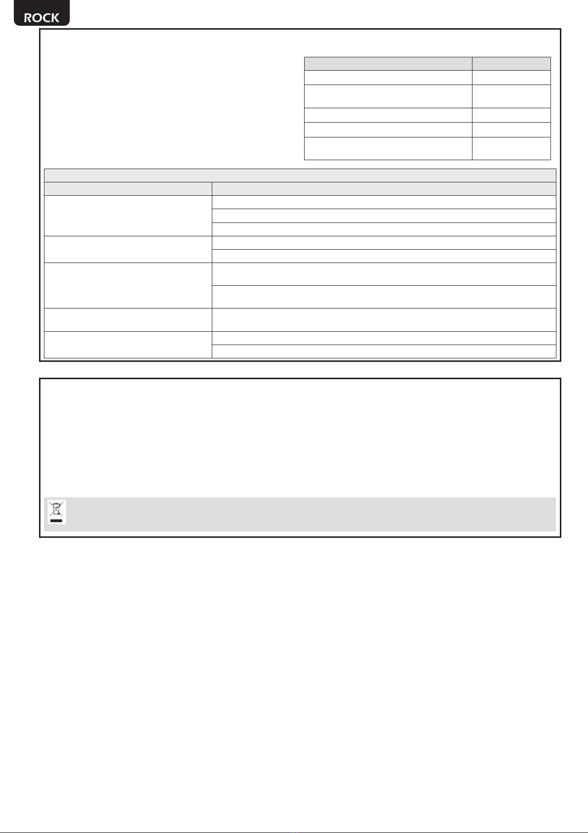
Assess the level of shock resistance desired and proceed with excavation:
Fixing via additional reinforcement
Excavate to a depth of approx. 155 cm.
The excavation must have dimensions of 140x190 cm.
Fixing via anchor bolts
Excavate to a depth of approx. 155 cm.
The excavation must have dimensions of 90x125 cm.
WARNING Pay attention to the direction of travel as indicated in Fig. 3.
4.3 Connection to sewer system
Make sure that the land has good draining capacity by introducing approx. 40 litres of water and checking emptying takes place in less
than 30 minutes. If this is not the case, drain the waters via piping to be connected to each individual formwork (pipe diameter 80
mm) and connected to the sewer system with siphon, or to a pit with a water emptying system.
4.4 Cementing via additional reinforcement
• Introduce gravel (grain with diameter of approx. 22/32 mm) with thickness of approx. 30 cm, making sure it is compacted well to
prevent future “settling withdrawals”.
• Lay the layer of geotextile (300 g.) on the compacted gravel.
• Position a PVC pipe with diameter of 200 mm and length of 220 mm in the centre of the hole and ABOVE the geotextile (the PVC pipe
is necessary to channel the rain water).
• Introduce concrete (RCK45 type) into the hole to a height of 200 mm, making sure that the pipe remains in the centre and escapes
by at least 20 mm.
Warning: the concrete casting must be level (check that the concrete base is level with the ground in order to obtain a good support for
the bollard).
Warning: make sure that the height from the base of the cementing just performed is 1000 mm at the road surface (Fig. 4c).
• Assemble the reinforcement cage as indicated in Fig. 6 (n°36 bars Ø8 and n°5 horizontal brackets to be fixed in an equidistant way,
using the classical metal wire for reinforcement).
• Place the cage inside the excavation, making sure is is true and plumb.
• Assemble the metal pit (Fig. 5) using the rivets supplied and fix it to the secondary frame using the relative bolts supplied.
• Place the metal pit complete with secondary frame, making sure it is plumb. The upper level of the secondary frame must be
positioned 20 mm higher with respect to ground height (to limit the entry of rain water into the pit).
Warning: make sure that the metal pit is positioned correctly with respect to the direction of travel.
• Assemble n°11 anchor bolts in Ø12 B450C steel bars as indicated in Fig. 3; make sure that improved adhesion steel bars are used.
• Position the flexible hose with diameter of 45 mm (for passage of the power supply and command cables) in the relevant pilot holes
of the formwork. The piping must be connected to the plant management and handling station.
• Introduce concrete (RCK4 type) all around the metal pit up to ground level and successively connect the projecting part to the road
surface.
Warning: make sure that the concrete casting is vibrated using suitable equipment in away to adhere correctly to the walls of the metal
pit and that the same remains above the ground level by at least 20 mm (Fig. 7).
WARNING All piping must be positioned with full respect of regulations in force.

EN-5
4.5 Cementing via anchor bolts
• Introduce gravel (grain with diameter of approx. 22/32 mm) with thickness of approx. 30 cm, making sure it is compacted well to
prevent future “settling withdrawals”.
• Lay the layer of geotextile (300 g.) on the compacted gravel.
• Position a PVC pipe with diameter of 200 mm and length of 220 mm in the centre of the hole and ABOVE the geotextile (the PVC pipe
is necessary to channel the rain water).
• Introduce concrete (RCK45 type) into the hole to a height of 200 mm, making sure that the pipe remains in the centre and escapes
by at least 20 mm.
Warning: the concrete casting must be level (check that the concrete base is level with the ground in order to obtain a good support for
the bollard).
Warning: make sure that the height from the base of the cementing just performed is 1000 mm at the road surface (Fig. 4c).
• Assemble the metal pit (Fig. 5) using the rivets supplied and fix it to the secondary frame using the relative bolts supplied.
• Place the metal pit complete with secondary frame, making sure it is plumb. The upper level of the secondary frame must be
positioned 20 mm higher with respect to ground height (to limit the entry of rain water into the pit).
Warning: make sure that the metal pit is positioned correctly with respect to the direction of travel.
• Position the flexible hose with diameter of 45 mm (for passage of the power supply and command cables) in the relevant pilot holes
of the formwork. The piping must be connected to the plant management and handling station.
• Introduce concrete (RCK4 type) all around the metal pit up to ground level and successively connect the projecting part to the road
surface.
Warning: make sure that the concrete casting is vibrated using suitable equipment in away to adhere correctly to the walls of the metal
pit and that the same remains above the ground level by at least 20 mm (Fig. 7).
WARNING All piping must be positioned with full respect of regulations in force.
4.6 Laying the traffic bollard (Fig. 8)
• Remove the cable cross platform from the structure by removing the protection caps and loosening the 4 underlying screws.
• Tighten 2 x M12 eye-bolts as indicated and lower the structure into the pit.
Warning: on lowering the structure, pay maximum attention not to pinch the power supply cable and to the position of the electrical box.
• Remove the eye-bolts and fix the structure tightly to the metal pit structure using the 8 countersunk head screws provided.
• Re-position the cable cross platform in its seat and fix it with the screws (and protection caps), which were previously removed (Fig.
9).
4.7 Release and manual movement (Fig. 10)
In the event of mains power failure, the bollard remains raised and the release device must be operated to lower it.
Operate as follows to do this:
• Unscrew the closure cap positioned on the head of the bollard.
• Insert the relevant key supplied, loosen anti-clockwise by approx. 1 turn and wait for the bollard to descend completely.
• To take the bollard back to working condition, turn the key clockwise.
WARNING Remember to tighten the cap on completion of the manual handling operations, so that the release device is always pro-
tected from water and dust.
WARNING The bollard may have uncontrolled movements during the release operation: pay maximum attention in order to prevent
every possible risk.

EN-6
WIRING DIAGRAM ROCK
Closing limit switch (FCC)
Common of the limit switch
Opening limit switch (FCA)
Microswitch of the head
+24 (LED) / +24 (Limit switch)
Buzzer
-24 (LED)
Common of the Pressure switch
Pressure switch
Grounding
Phase (solenoid valve) - 230V
Neutral (solenoid valve) - 230V
Motor march (CLOSE)
Motor march (OPEN)
Common
Microswitch of the head
F
N
3 x 1,5 mm2
OMNIPOLAR CIRCUIT BRAKER
POWER SUPPLY
230V~ 50Hz ±10%
1
2
3
4
5
6
7
8
9
10
11
12
13
14
15
16
Black
Violet
Red
Pink
White
Brown
Green
Grey
Yellow
Yellow/green
Black 5
Black 4
Black 3
Black 2
Black 1
Blue
2
1
910 1112 13 14 15 16
17
18
19
20
21
22
23
24
25
26
27
28
30 2932 31
34 5 678
WARNING LOCK
FLASH
230V
MOT 1 MOT 2
34 33
WL/FL24V
N
F
ENC_M2ENC_M1
CON 1
CON 2
COM
IN_1
COM
IN_2
COM
IN_3
COM
IN_4
COM
IN_5
COM
IN_6
DISPLAY
Serial N°
000X XXXXXX
ATTENTION The total absorption of the integrated standard components
supplied with 24V is ~100mA (limit switch, LED head, buzzer).
ATTENTION For the wiring of 2 bollards to a single control unit NET230N,
it will be necessary to provide a separate power source for any 24V
accessories that should normally be connected to the +24VAUX and
+24_ST outputs (photocells, radio receivers, etc.).

EN-7
6 COMMISSIONING
The commissioning phase is extremely important for ensuring maximum system safety, as well as legal and regulatory compliance,
namely with all the requirements of EN 12445, which establishes the test methods of the plants.
DEA System would like to emphasize that any system installation, cleaning or repair operations must only be carried out by qualified
personnel, who must conduct all the tests necessary based on the risks present;
6.1 Inspecting the plant
Inspection is essential to check correct system installation. DEA System summarises the correct inspection of all automation in 4
simple steps:
• Make sure that described in paragraph 2 “SUMMARY OF WARNINGS” is strictly observed;
• Carry out the bollard raising and lowering tests tests, checking that the movement corresponds with that envisioned. To this regard,
we recommend you run several trials to identify any assembly or adjustment defects;
• Make sure all safety devices connected to the system operate correctly;
WARNING The use of spare parts not indicated by DEA System and/or incorrect assembly may cause hazardous situations to people,
animals and property; they may also cause product malfunctions; always use the parts indicated by DEA System and scrupulously
follow the assembly instructions.
6.2 Release and manual manoeuvre
In the case of plant anomalies or simple power failure, perform the manual emergency manoeuvre and lower the bollard (Fig. 10).
Know-how regarding operation of the release device is very important, since in times of emergencies slow action in operating this device
can cause hazardous situations.
WARNING The safety and efficacy of moving the automation manually is only guaranteed by DEA System if the system has been pro-
perly installed using original accessories.
5 ELECTRICAL CONNECTIONS
Run the motor connections following the wiring diagrams.
WARNING For adequate electrical safety, keep low safety voltage wires (controls, electro-locks, antenna, auxiliary power) clearly separate
from 230V ~ power wires (minimum 4 mm in air or 1 mm via supplementary insulation) placing them in plastic raceways and securing
them with adequate clamps near terminal boards.
WARNING For connection to the mains, use a multipolar cable having a minimum section 3x1,5 mm² and complying with the current
regulations. For connecting the motors, use a minimum cross section 1,5 mm² cable and complying with the current regulations. As
an example, if the cable is out side (outdoor), must be at least equal to H05RN-F, whereas if it (in a raceway), must be at least equal to
H05VV-F.
WARNING All wires must be striped and unsheathed in the immediate vicinity of terminals. Keep wires slightly longer to subsequently
eliminate any excess.
WARNING Maintain the ground conductor at a major length respect the active conductors so that, if the cable exit from its fixing housing,
the active conductors tighten up as first.
WARNING In the ROCK versions without a cable, separate wiring must be provided for the motor supply (FG 16x1,5mmq) and the controls
(FG 10x0,5mmq).
After connection, it is advisable to seal the wiring box with contact sealant (e.g. Etelec Replaygel).
Program the control board to complete all adjustments. It is now possible to supply a complete installation in compliance with all stan-
dards required for gate automation. See the instructions provided with the control panel to be connected.
WARNING
If the system foresees the installation of 2 bollards, for the wiring of the completion accessories, it will be necessary to
integrate an input expansion card art. NET-EXP.
Finally, verify that all adjustments operations have been correctly performed and that safety devices and unlocking device properly
work.

EN-8
7 MAINTENANCE
Good preventive maintenance and regular inspection
ensure long working life. In the table below you will find a listo f
inspections/maintenance operations to be programmed and
executed periodically.
Consult the TROUBLE-SHOOTING” table whenever anomalies
are observed in order to find the solution to the problem and
contact DEA System directly whenever the solution required is not
provided.
TYPE OF INTERVENTION PERIODICITY’
Clean external surfaces 6 months
Check status of wear of the retro-reflective tape
on the rod 6 months
Check status of luminous indicators 6 months
Check functioning of release device 6 months
Check operation of the command unit and the
safety devices 6 months
TROUBLESHOOTING
Description Possible solutions
The bollard rises for a few centimetres and
lowers immediately.
Check correct wiring of the safety pressure switch.
Check correct adjustment of the pressure switch.
Replace the pressure switch.
As soon as the bollard reaches the high position,
it inverts immediately.
Check correct wiring of limit switch.
Check the correct adjustment of the high position limit switches.
The bollard does not rise but remains low in
opening position.
Check that the bollard is re-blocked hydraulically (after an eventual emergency manual release Fig.
10).
Check correct operation of the solenoid valve (art. ROCK/EL not supplied) and replace the component
if necessary.
The bollard does not lower but remains low in
closing position.
Check that there are no obstructions between the sliding ring and the cylinder. Try to shake the cylinder
to facilitate descent.
The luminous and acoustic indicators do not
work.
Check the correct wiring of the power supply connector positioned under the cylinder head.
Replace the circuit.
8 PRODUCT DISPOSAL
ROCK consists of materials of various types, some of which can be recycled (electrical cables, plastic, aluminum, etc. ..) while others
must be disposed of (electronic boards and components).
Proceed as follows:
1. Disconnect the power supply;
2. Disconnect and disassemble all the accessories connected. Follow the instructions in reverse to that described in the section
“Installation”;
3. Remove the electronic components;
4. Sorting and disposing of the materials exactly as per the regulations in the country of sale.
WARNING In line with EU Directive 2012/19/EU for waste electrical and electronic equipment (WEEE), this electrical product must
not be disposed of as unsorted municipal waste. Please dispose of this product by returning it to your local municipal collection
point for recycling.

I-1
Pos. Descrizione - Description - Description - Beschreibung - Descripción - Descrição - Opis - Описание
1 ROCK
2Selettore a chiave antiscasso - Anti lock-picking key switch - Sélecteur à clé anti-intrusion - Einbruchfester Schlüsselschalter - Selector a llave antisabotaje - Interruptor de
chave burglar - Przełącznik kluczowy wandaloodporny - Замковый выключатель
3 Radiocomando - Remote-control - Radiocommande - Funksteuerung - Radiocomando - Comando via rádio - Nadajnik - Пульт ДУ
4 Selettore digitale - Radio keypad - Digicode radio - Digitalwahlschalter - Teclado digital radio - Teclado via radio - Bezprzewodowa klawiatura - Радио кодовая панель
5Semaforo a led 230V - 230V led traffic light - Feux LED 230V - Ampel 230V - Semáforo de señalización 230V - Semáforo de trânsito com luz LED 230V - Sygnalizator świetlny
230V - 230Всветодиодный светофор
6Rilevatore per spira magnetica - Loop detector - Détecteur de boucle magnétique - Induktionsschleifen Dedektor - Detector de masas metálicas - Detector de espiras magnéti-
cas - Detektor magnetyczny metali - Магнитный контурный детектор
Collegarsi alla rete 230 V ± 10% 50-60 Hz tramite un interruttore onnipolare o altro dispositivo che assicuri la onnipolare disinserzione della rete, con una distanza di aper-
tura dei contatti ≥3 mm - Make the 230V ± 10% 50-60 Hz mains connection using an omnipolar switch or any other device that guarantees the omnipolar disconnection of
the mains network with a contact opening distance of 3 mm - Connectez-vous au réseau 230 V ± 10% 50-60 Hz au moyen d’un interrupteur omnipolaire ou d’un autre di-
spositif qui assure le débranchement omnipolaire du réseau, avec un écartement des contacts égal à 3 mm. - Den Anschluss an das 230 V ~ ± 10% 50-60 Hz Netz mit einem
Allpolschalter oder einer anderen Vorrichtung vornehmen, durch die eine allpolige Netzunterbrechung bei einem Öffnungsabstand der Kontakte von ≥3 mm gewährleistet
wird. - Efectuar la conexión a una línea eléctrica 230 V ± 10% 50-60 Hz a través de un interruptor omnipolar u otro dispositivo que asegure la omnipolar desconexión de la
línea, con 3 mm de distancia de abertura de los contactos. - Ligue na rede de 230 V. ± 10% 50-60 Hz mediante um interruptor omnipolar ou outro dispositivo que assegure
que se desliga de maneira omnipolar da rede, com abertura dos contactos de pelo menos 3 mm. de distância - Podłączyćsiędo sieci 230 V ± 10% 50-60 Hz poprzez
przełącznik jednobiegunowy lub inne urządzenie które zapewni brak zakłóceńw sieci, przy odległości między stykami ≥3 mm. - Подключайтесь ксети 230V ± 10% 50-60
Гц спомощью многополюсного выключателя или используйте любое другое устройство, которое гарантирует многополюсное отключение питающей сети срасстоянием
между контактами от ≥3 мм ибольше.
Collegare a terra tutte le masse metalliche - All metal parts must be grounded - Connectez toutes les masses métalliques à la terre - Alle Metallteile erden - Conectar con
la tierra todas las masas metálicas - Realize ligação à terra de todas as massas metálicas - Uziemićwszystkie elementy metalowe. - Все металлические части должны быть
заземлены.
Esempio di installazion tipica - Example of typical installation - Exemple d’installation typique - Installationsbeispiel - Ejemplo de instalación típica -
Exemplo de instalação típica - Przyład standardowego systemu automatyzacji - Пример типового монтажа
DEA System fornisce queste indicazioni che si possono ritenere valide per un impianto
tipo ma che non possono essere complete. Per ogni automatismo, infatti, l’installa-
tore deve valutare attentamente le reali condizioni del posto ed i requisiti dell’instal-
lazione in termini di prestazioni e di sicurezza; sarà in base a queste considerazioni
che redigerà l’analisi dei rischi e progetterà nel dettaglio l’automatismo. - DEA System
provides the following instructions which are valid for a typical system but obviously
not complete for every system. For each automatism the installer must carefully eva-
luate the real conditions existing at the site. The installation requisites in terms of
both performance and safety must be based upon such considerations, which will also
form the basis for the risk analysis and the detailed design of the automatism. - DEA
System fournit ces indications que vous pouvez considérer comme valables pour une
installation-type, même si elles ne peuvent pas être complètes. En effet, pour chaque
automatisation, l’installateur doit évaluer attentivement les conditions réelles du site
et les pré-requis de l’installation au point de vue performances et sécurité ; c’est sur
la base de ces considérations qu’il rédigera l’analyse des risques et qu’il concevra
l’automatisation d’une manière détaillée. - Diese Angaben von DEA System können
als gültig für eine Standardanlage angesehen werden, können aber nicht erschöpfend
sein. So muss der Installationsfachmann für jedes Automatiksystem sorgfältig die Vo-
raussetzungen des Installationsortes sowie die Leistungs- und Sicherheitsanforderun-
gen an die Installation abwägen; aufgrund dieser Überlegungen muss er die Risiko-
bewertung erstellen und genau das Automatiksystem entwickeln. - DEA System facilita
estas indicaciones que pueden considerarse válidas para una instalación tipo pero
que no pueden considerarse completas. El instalador, en efecto, tiene que evaluar
atentamente para cada automatismo las reales condiciones del sitio y los requisitos
de la instalación por lo que se refiere a prestaciones y seguridad; en función de estas
consideraciones redactará el análisis de riesgos y efectuará el proyecto detallado del
automatismo. - DEA System fornece estas indicações que podem ser consideradas
válidas para o equipamento padrão, mas que podem não ser completas. Para cada
automatismo praticamente o técnico de instalação deverá avaliar com atenção as
condições reais do sítio e os requisitos da instalação em termos de performance e
de segurança; será em função destas considerações que realizará uma análise dos
riscos e projectará. - DEA System dostarcza wskazówek, do wykorzystania w typowej
instalacji ale nie będąone nigdy kompletne. Dla każdego typu automatyki, instalator
musi sam oszacowaćrealne warunki miejsca montażu i wymogi instalacyjne mając na
uwadze przepisy dotyczące bezpieczeństwa. Na podstawie zebranych informacji będzie
w stanie przeanalizowaćzagrożenia mogące wystąpići zaprojektowaćw szczegółach
automatyzację. - DEA System предлагает рекомендации , которые действительны для
типовой системы, но, очевидно, не обязательны для каждой конкретной установки.
Для каждого конкретного случая установщик должен тщательно оценить реальные
условия. Устройства для установки оцениваются сточки зрения производительности
ибезопасности, которые необходимы для анализа рисков идетального
проектирования системы автоматизации.

I-2
1025 700
150
162
Ø274 x6
817
540
817
540
1
2
Assicurarsi che il terreno abbia una buona capacità drenante immettendo circa 40 litri d’acqua e verificando che lo svuotamento
avvenga in meno di 30 minuti; Make sure that the land has good draining capacity by introducing approx. 40 litres of water and checking
emptying takes place in less than 30 minutes; S’assurer que le terrain possède une bonne capacité drainante en introduisant environ
40 litres d’eau et en vérifiant que le vidage ait lieu en moins de 30 minutes; Stellen Sie sicher, dass der Boden eine gute
Drainagekapazität hat, indem Sie ca. 40 Liter Wasser einfüllen und überprüfen, ob das Wasser in weniger als 30 Minuten abläuft;
Asegúrese de que el terreno tenga una buena capacidad drenante introduciendo uno 40 litros de agua y comprobando que el vaciado
se realice en menos de 30 minutos; Certificar-se que o solo tenha uma boa capacidade drenante introduzindo cerca de 40 litros de
água e verificando que o esvaziamento aconteça em menos de 30 minutos; 8SHZQLýVLĘŮHJUXQWPDGREUĉ]GROQRŒýRGSURZDG]DQLD
ZRG\ZVWU]\NXMĉFRNRâROLWUyZZRG\LVSUDZG]DMĉFF]\RSUyŮQLDQLHRGE\ZDVLĘZF]DVLHNUyWV]\PQLŮPLQXWǟǭDZǰǴǾȈǽȋǮǾǺǸȃǾǺ
dzDZǸǷȋǺǭǷǬǰǬDZǾȁǺǼǺȄDZǵǰǼDZǹǬDzǹǺǵǽǻǺǽǺǭǹǺǽǾȈȊǻǺǯǷǺȅǬȋǺǶǺǷǺǷǴǾǼǺǮǮǺǰȇǴǶǺǹǾǼǺǷǴǼǿȋȃǾǺǮǻǴǾȇǮǬǹǴDZǻǼǺǴǽȁǺǰǴǷǺ
ǮǾDZȃDZǹǴDZǻǺǶǼǬǵǹDZǵǸDZǼDZǸǴǹǿǾ
AB
140 190
con armatura di rinforzo - with additional rein-
forcement - avec l’armature additionnelle - dur-
ch zusätzliche Armierungseisen - con soporte
adicional - com armação adicional - zdoda-
tkowym wzmocnieniem - ǽǬǼǸǴǼǺǮǬǹǴDZǸ
90 125
con sole zanche - with anchor bolts - avec
le barres - durch Krallen - con grapas - com
braçadeiras - ze ŒUXEDPL fundamentowymi - ǽ
ǬǹǶDZǼǹȇǸǴǭǺǷǾǬǸǴ

I-3
550
45°
100
3
RUNNING
DIRECTION
RUNNING
DIRECTION
RUNNING
DIRECTION
Con sole zanche - With anchor bolts - Avec
le barres - Durch Krallen - Con grapas - Com
EUDoDGHLUDV=HŒUXEDPLIXQGDPHQWRZ\PL
&ǬǹǶDZǼǹȇǸǴǭǺǷǾǬǸǴ
&RQ DUPDWXUD GL ULQIRU]R :LWK DGGLWLRQDO UHLQIRUFHPHQW $YHF
l’armature additionnelle - Durch zusätzliche Armierungseisen - Con
VRSRUWH DGLFLRQDO &RP DUPDomR DGLFLRQDO = GRGDWNRZ\P
Z]PRFQLHQLHP&ǬǼǸǴǼǺǮǬǹǴDZǸ
4a

I-4
4b
1Ghiaia - Gravel - Gravier - Kies - Grava - GraYLOKDŭZLUǏǼǬǮǴǵ 2Geotessuto - Geotextile - Géotextile - Geotextilschicht - Geotejido
- Geotêxtil - GeoZâyNQLQLHǏDZǺǾDZǶǽǾǴǷȋ
3
Tubo di scarico - DraiQpipe - Tuyau G·pFKDSSHPHQW -
(QWZlVVHUXQJVURKU - Tubo de escape - RXUDZ\GHFKoZa - 4
Raccordo a rete fRJQDULD - &RQQHFWLRQ to seZer system - Raccord
au système G·pJRXW - KDQDOLVDWLRQVDQVFKOXVV - &RQe[LyQ al siste-
ma de DOFDQWDULOODGR - -XQomRD sistHPDGHiJXDVUHVLGXDLV Po-
GâĉF]HQLHV\Vtemu NDQDOL]DF\MQHJRǤǾǿȂDZǼǶǬǹǬǷǴdzǬȂǴǴ
ǎȇȁǷǺǻǹǬȋǾǼǿǭǬ
4c Attenzione: assicurarsi che la quota dalla base della
cementazione appena eseguita al manto stradale sia di
1000 mm;
Warning: make sure that the height from the base of the
cementing just performed is 1000 mm at the road surface;
Attention: s’assurer que la hauteur à partir de la base de la
cimentation qui vient d’être exécutée au revêtement de la
route, soit de 1000 mm;
Achtung: Die Höhe von der Basis des gerade ausgeführten
Betongusses bis zur Fahrbahnoberfläche muss 1000 mm
betragen;
Atención: asegúrese que la cuota de la base de la cemen-
tación apenas realizada en el pavimento sea de 1000 mm;
Atenção: assegurar-se que a quota da base da cemen-
tação apenas realizada no manto rodoviária seja de 1000
mm;
Uwaga: XSHZQLý VLĘ ŮH Z\VRNRŒý RG SRGVWDZ\ W\OH FR
Z\NRQDQHJR FHPHQWRZDQLD QD QDZLHU]FKQL GURJL Z\QRVL
1000 mm;
ǎǹǴǸǬǹǴDZ ǿǭDZǰǴǾȈǽȋ ȃǾǺ ǮȇǽǺǾǬ ǺǾ ǺǽǹǺǮǬǹǴȋ ǾǺǷȈǶǺ
ȃǾǺ ǮȇǻǺǷǹDZǹǹǺǯǺ ȂDZǸDZǹǾǴǼǺǮǬǹǴȋ ǰǺ ǻǺǮDZǼȁǹǺǽǾǴ
ǰǺǼǺǯǴǽǺǽǾǬǮǷȋDZǾǸǸ

I-5
5
6a
A x1
Bx4
Cx1
D x4
x40
x24

I-6
6b
6c

I-7
7
15÷30
8Attenzione: nel calare la struttura, prestare massima attenzione a non pizzica-
re il cavo di alimentazione e alla posizione della scatola elettrica;
Warning: on lowering the structure, pay maximum attention not to pinch the
power supply cable and to the position of the electrical box;
Attention: au moment de faire descendre la structure, faire très attention à ne
pas pincer le câble d’alimentation et à la position du boitier électrique;
Achtung: Achten Sie beim Absenken des Pollers darauf, dass das Netzkabel
und die Position des Schaltgehäuses nicht eingeklemmt oder angestoßen wird;
Atención: durante la bajada de la estructura preste la máxima atención a no
pellizcar el cable de alimentación y a la posición de la caja eléctrica;
Atenção: ao abaixar a estrutura, prestar a máxima atenção a não picar o cabo
de alimentação e à posição da caixa elétrica;
Uwaga:SRGF]DVRSXV]F]DQLDNROXPQ\QDOHŮ\XZDŮDýDE\QLHSU]HFLĉýSU]HZR-
GX]DVLODMĉFHJRLQLHQDUXV]\ýSR]\FMLSXV]NLHOHNWU\F]QHM
ǎǹǴǸǬǹǴDZ ǻǼǴ ǺǻǿǽǶǬǹǴǴ ǶǺǹǽǾǼǿǶȂǴǴ ǺǭǼǬǾǴǾȈ ǺǽǺǭǺDZ ǮǹǴǸǬǹǴDZ ǹǬ ǾǺ
ȃǾǺǭȇǹDZǻDZǼDZDzǬǾȈȄǹǿǼǻǴǾǬǹǴȋǴǻǺǷǺDzDZǹǴDZȉǷDZǶǾǼǴȃDZǽǶǺǯǺǭǷǺǶǬ

I-8
10
9

I-9
Tabella “ACCESSORI PRODOTTO”, Table “PRODUCT ACCESSORIES”, Tableau “ACCESSOIRES PRODUITS”, Tabelle „PRODUKTZU-
BEHÖR”, Tabla “ACCESORIOS PRODUCTO”, Tabela “ACESSÓRIOS DO PRODUTO”, Tabela “AKCESORIA DODATKOWE”,
Таблица “АКСЕССУАРЫ ИЗДЕЛИЯ”.
Article
Code
Descrizione, Description, Description,
Beschreibung, Descripción, Descrição, Opis, Oписания
ROCK/LOCK
659022
Serratura di sicurezza per dissuasore art. ROCK - Safety lock for bollard art. ROCK -
Serrure avec clé personnalisée pour déverrouillage art. ROCK - Sicherheitsschloss
zu Poller Art. ROCK - Cerradura de seguridad para disuasor art. ROCK - Fechadura de
segurança para dissuasor de estacionamento art. ROCK - Skrzynia montażowa dla art.
ROCK - Предохранитель для арт. ROCK
ROCK/B
659070
Cassaforma per dissuasore art. ROCK Ø=273mm h=700mm - Framework for bollard
art. ROCK Ø=273 h=700mm - Caisson de fondation pour borne escamotable art. ROCK
Ø=273 h=700mm - Einlassrahmen zu Poller Art. ROCK Ø=273 h=700mm - Cajón de
cimentación art. ROCK Ø=273 h=700mm - Estrutura para dissuasor art. ROCK Ø=273
h=700mm - Skrzynia fundamentowa dla art. ROCK Ø=273mm h=700mm - Опалубка
для изделия для столбиков ROCK Ø = 273 мм h = 700 мм
ROCK/RE
659060
Riscaldatore elettrico antigelo - Antifreeze heater - Dispositif de chauffage électrique
antigel - Frostschutzheizung - Calentador eléctrico - Aquecedor eléctrico anti-gelo
- Podgrzewacz elektryczny zapobiegający zamarzaniu - Антифриз Электрический
подогреватель
ROCK/EL
659062
Solenoide per valvola discesa rapida - Solenoid with power supply cable - Electrovanne
avec câble d’alimentation - Magnet mit Netzkabel - Electrovàlvula con cable de
alimentación - Electrovalvula com cabo de alimentação - Elektrozawór z kablem
zasilającym - Электромагнитный клапан для быстрого спуска
ROCK/C
659071
Chiusino per cassaforma per dissuasore art. ROCK - Manhole close for bollard art. ROCK
- Couvercle du caisson de fondation pour borne escamotable art. ROCK - Schachtdeckel
zu Poller Art. ROCK - Tapa para cajón de cimentación art. ROCK - Tampa para a estrutura
do dissuasor de estacionamento art. ROCK - Studzienka podziemna dla art. ROCK -
Крышка люка для арт. ROCK
ROCK/MICRO
659063
Microinterruttoredi sicurezzaopzionale- Optionalsafetymicroswitch-Microinterrupteur
de sécurité en option - Optionaler Sicherheitsmikroschalter - Microinterruptor
de seguridad opcional - Microinterruptor de segurança opcional - Opcjonalny
mikroprzełącznik bezpieczeństwa - По желанию микровыключатель безопасности

I-10
This manual suits for next models
1
Table of contents
Other Dea Control System manuals