of
INDUSTRIAL PUMPS
.debem.com
Srev.
Title
CHAPTER
Sequences
Contents
Graphs
Numbers
PAGE
CAUTIONS
WARNINGS
and NOTES
Personal
Authorised
Title
SECTION
CONTENTS OF THE ORIGINAL INSTRUCTIONS
Thetopicsarecoveredinordertoallowaclassicationoftheinformationandtheprofessional address to which
they are addressed, so that the contained information can be immediately and directly consulted.
The manual is divided into chapters and related sections that deal with the operational topics for correct installation,
use and maintenance of the pump, with exposure divided into numbered sequences.
The pages are characterised by the following structure and contents:
• A bar has been created at the beginning of each section which, through symbols, indicates the personnel
authorised to perform the operation, the prohibitions to be observed, the obligations and the Personal Protective
Equipment (PPE) that must be used;
• The residual risk that may occur during the operations is highlighted by appropriate symbols, integrated with the
text.
Special symbols are used within the manual to highlight and differentiate particular information or suggestions
important for the safety and/or correct installation, maintenance or replacement of the pump.
Withtheseprecautions,theManufacturerintendstodrawtheattentionofqualiedTechnicianstotheCAUTIONS,WARN-
INGS or NOTES concerning them.
For any doubts or clarications regarding the contents of this manual, do not hesitate to contact the Man-
ufacturer’s Technical Service.
Tel. +39 / 0331 074034
Fax +39 / 0331 074036
website: www.debem.com
INDUSTRIAL PUMPS
Translation of original instructions -SCUBIC - SBOXER rev. 01-20
Chapter / 2 - Introductory Information
2.5 PUMP DESCRIPTION
2.5.1 FUNCTIONING PRINCIPLES
Thepneumatic pumps of the SCUBIC and SBOXER series consist of an internal insert that directs air to the
diaphragms of the two pumping bodies by moving them via a central pin. The diaphragms integral with
the central driving pin are operated with alternating motion in two stages (suction-delivery) and constitute
the pumping elements.
The respective uid retaining ball valves are housed between the two pumping chambers and the pump
delivery and suction ducts.
The two-stage operating principle operates simultaneously (while one chamber is in the suction phase, the
second chamber is in the discharge phase), guaranteeing negative suction, high head and the pumping of
uids with high viscosity and solid parts in suspension (see 2.6 CHARACTERISTICS TECHNICAL DATA).
2.5.2 INSTALLATION REQUIREMENTS AND FEATURES
SCUBIC and SBOXER air pumps are self-priming
and
can run dry and allow varying the operating speed
even during service.
They can be used for the recirculation and pumping of liquids with high viscosity and solid parts in
suspension (see 2.6 TECHNICAL FEATURES).
Their operation is envisioned for
horizontal installations,
above and below head, with precautions compliant with the features of each model (see 2.6 TECHNICAL
FEATURES).
The suction and delivery pipes can be suitably sized (never smaller than the pump) to ensure minimum ow
rates and optimal performance.
2.6 INTENDED USE AND IMPROPER USES
2.6.1 INTENDED USE
The air-driven SCUBIC and SBOXER pumps have been designed and constructed to pump liquids and
aggressive liquids (acid or alkaline) with chemical composition and temperatures compatible with the
pump materials and apparent viscosity of between 1 and 20,000 Cps at 20°C (see the Technical Data
Sheet of the Pump model); viscosities higher than 20,000 Cps at 20°C result in physical factors that
require correct evaluation, therefore, it is always necessary to contact the Manufacturer’s Techni-
cal Department in advance.
The maximum temperature allowed for process uid depends on and/or is downgraded by the construction
material of the pump and system.
CAUTION
The maximum temperature limits are based on two factors, mechanical and corrosive. Some of the u-
ids used may signicantly reduce the maximum safety temperatures due to the high corrosive content.
Conformity with the ATEX marking afxed on the pump is no longer ensured when the maximum
temperature is exceeded.
2.6.2 CALCULATION OF MAXIMUM FLUID TEMPERATURE (for Zone 1 - Zone 21)
Below is
the formula for determining the maximum permissible uid process temperature for
SCUBIC e
SBOXER
pumps in CONDUCT version:
II 2G Ex h IIB T4 Gb and
II 2D Ex h IIIB T135°C Db
) for installation in
Zone 1 - Zone 21.
Temperature Class
ATEX
IECEx
Calculation Factor
(only for Zone 1- Zone 21) Maximum temperature of
Fluid process
ATEX T4 - Tx 55°C = Tf 80°C
IECEX 135°C - 55°C = 80°C
4.3.4a
4.3.4b
of
INDUSTRIAL PUMPS
www.debem.com
S
BOXER
rev
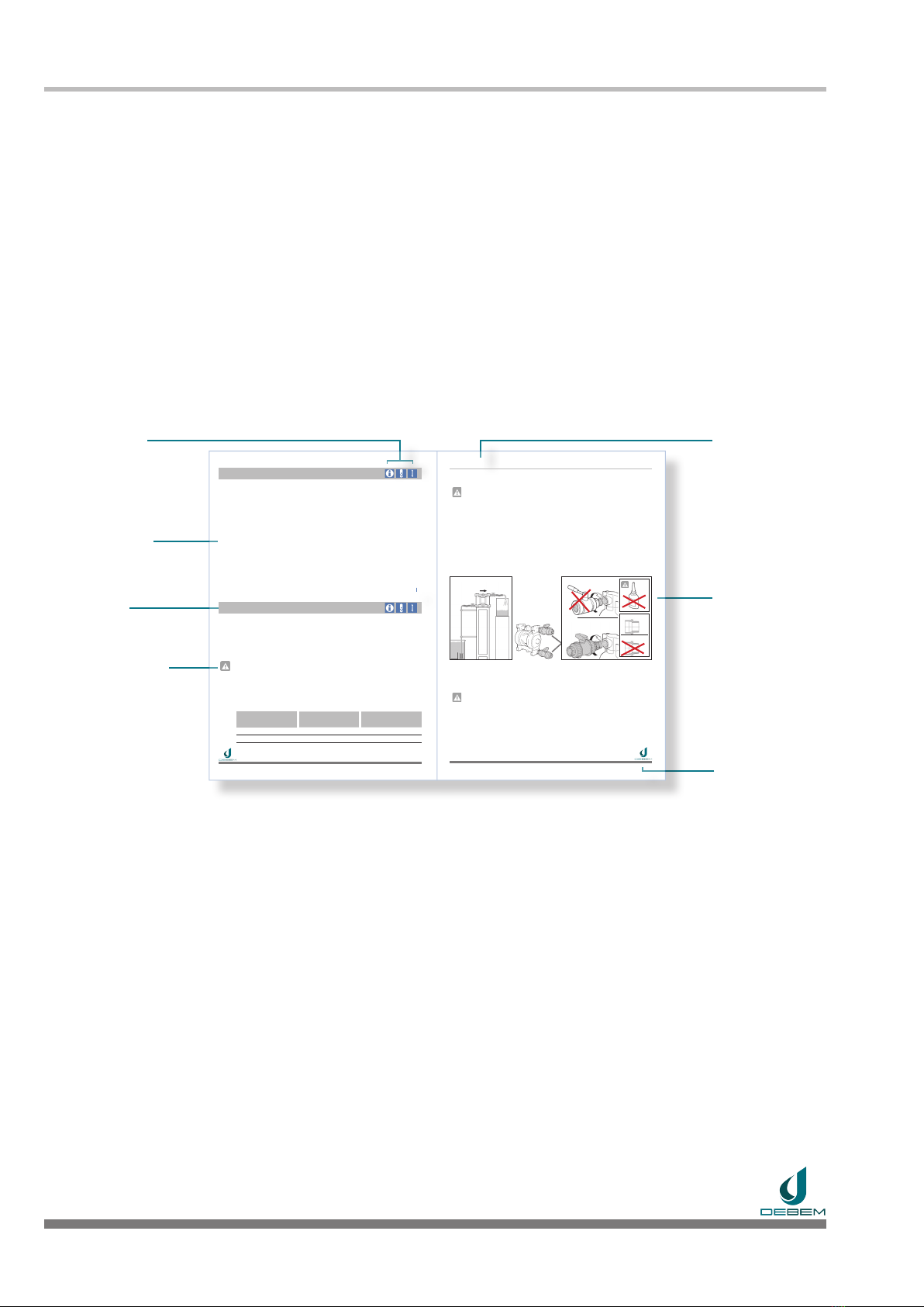
2.5 m
MAX 5 m
Pump
PP
Valve
INOX
OK
Valve
PP
Pump
PP
Conical gas
Cylindrical gas
OK
PRODUCT CIRCUIT CONNECTION
After positioning, it is possible to connect the pump to the product circuit as follows:
CAUTION: risk of chemical reactions to water
Before installing the pump for use with liquids that react with tap water, it is necessary to open the product
circuit and dry all internal surfaces.
Product system piping requirements
• Theconnectionttingsmustbemade ofthesamematerialas thepumpwithcylindricalthreads(do
not use conical threads);
• Theconnectiontothepumpmustbemadewithapieceofexiblehosewithametalcore(directcon-
nection to the pump with a rigid hose is prohibited);
• Allexistinghosesmustbereinforcedwithametalcore;
• Piping must be self-supported and must not burden on the pump;
• Correctsizingofthe(suctionanddischarge)ductsforthecorrectsuctionspeed;
• Producton/offvalves(suctionanddelivery,thatdonotcausepressuredrops);
• Withparticulatematterinsuspension,installaproperlysizedsuctionstraineronthesuctionside(surface
area2.5/3timesthesuctionsectionofthepumpwithmaximumpermittedslot);
• Withproductsthatcrystallise,provideawashingorstrippingcircuit(withcompatibleproducts);
• Productductscleaninsideandwithoutsolidprocessingresidues(shavings,particulates,etc.).
Diaphragm pumps with negative suction are affected by the following factors:
- Fluid viscosity - specic uid weight - diameter - length and/or bends on the suction.
Positionthepumpascloseaspossibletothesamplingpoint(within2.5m)andinallcasesnevermore
than 5 m. The diameter of the suction pipe should never be smaller than that of the pump connection; it
shouldbeincreasedasthedistanceorviscosityoftheuidincreases.
CAUTION:risk of premature wear and/or diaphragm breakage.
Theuidtobepumpedwithnegativesuctionmustneverexceedaviscosityof5,000Cpsat20°Canda
specicweightof1.4Kg/l.
Higher viscosities result in physical factors that require correct evaluation, therefore, it is always neces-
sary to contact the Manufacturer’s Technical Department in advance.
SCUBIC and SBOXER series pumps are supplied with product connection seats with cylindrical Gas
threads. For connectionstothepumpmanifolds,useonlyttingswithcylindricalgasthreads(notconical)
of the same material as the pump.
Example: (PP pump = PPttings)or(INOX pump = INOX ttings).
On the delivery and discharge manifold install a manual valve of the same diameter as the pump inlet
(neversmaller)orlargerfornegativesuctionsorforuidswithhighviscosity.
If necessary, load two turns of PTFE tape on the thread and tighten the valves onto the
pumpmanifolds(withmoderateclampingpressure)untilthesealisensured.