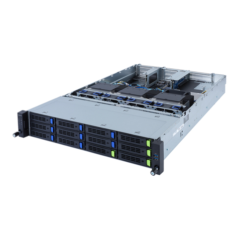
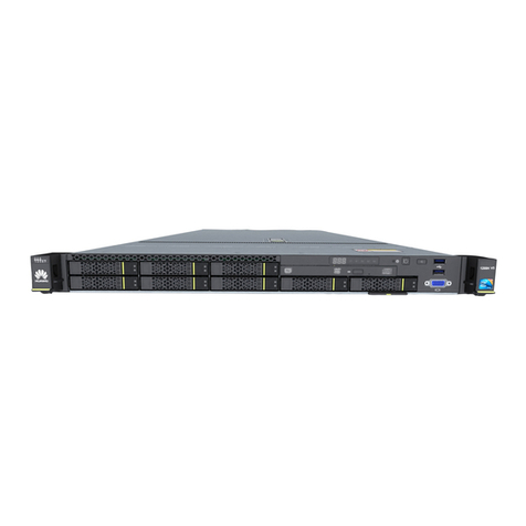
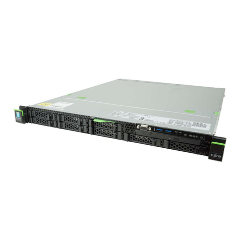
DEC AlphaServer 8200 User manual

digital equipment corporation
maynard, massachusetts
AlphaServer 8200/8400
System Technical Manual
Order Number EK–T8030–TM. A01
The Digital AlphaServer 8200 and 8400 systems are designed around the
DECchip 21164 CPU. The TLSB is the system bus that supports nine nodes in
the 8400 system and five nodes in the 8200 system. The AlphaServer 8400 can
be configured with up to six single or dual processor CPU modules (KN7CC),
seven memory modules (MS7CC), and three I/O modules (KFTHA and
KFTIA). One slot is dedicated to I/O and is normally occupied by the inte-
grated I/O module (KFTIA) that supports PCI bus, XMI, and Futurebus+
adapters. All other nodes can be interchangeably configured for CPU or mem-
ory modules. The AlphaServer 8200 can be configured with up to three CPU
modules, three memory modules, and three I/O modules.

First Printing, May 1995
The information in this document is subject to change without notice and should not be construed as a com-
mitment by Digital Equipment Corporation.
Digital Equipment Corporation assumes no responsibility for any errors that may appear in this document.
The software, if any, described in this document is furnished under a license and may be used or copied only
in accordance with the terms of such license. No responsibility is assumed for the use or reliability of soft-
ware or equipment that is not supplied by Digital Equipment Corporation or its affiliated companies.
Copyright © 1995 by Digital Equipment Corporation.
All Rights Reserved.
Printed in U.S.A.
The following are trademarks of Digital Equipment Corporation: AlphaGeneration, AlphaServer, DEC,
DECchip, DEC LANcontroller, OpenVMS, StorageWorks, VAX, the AlphaGeneration logo, and the DIGITAL
logo.
OSF/1 is a registered trademark of the Open Software Foundation, Inc. Prestoserve is a trademark of Legato
Systems, Inc. UNIX is a registered trademark in the U.S. and other countries, licensed exclusively through
X/Open Company Ltd.
FCC NOTICE: The equipment described in this manual generates, uses, and may emit radio frequency en-
ergy. The equipment has been type tested and found to comply with the limits for a Class A computing de-
vice pursuant to Subpart J of Part 15 of FCC Rules, which are designed to provide reasonable protection
against such radio frequency interference when operated in a commercial environment. Operation of this
equipment in a residential area may cause interference, in which case the user at his own expense may be
required to take measures to correct the interference.

iii
Contents
Preface ............................................................................................................................................ xv
Chapter 1 Overview
1.1 Configuration ................................................................................................................ 1-1
1.2 Bus Architecture ........................................................................................................... 1-2
1.3 CPU Module .................................................................................................................. 1-3
1.3.1 DECchip 21164 ...................................................................................................... 1-3
1.3.2 Backup Cache ......................................................................................................... 1-4
1.3.3 TLSB Interface ....................................................................................................... 1-4
1.3.4 Console Support Hardware.................................................................................... 1-4
1.4 Memory Module ............................................................................................................ 1-4
1.5 I/O Architecture ............................................................................................................ 1-5
1.6 Software......................................................................................................................... 1-6
1.6.1 Console .................................................................................................................... 1-6
1.6.2 OpenVMS Alpha ..................................................................................................... 1-7
1.6.3 Digital UNIX........................................................................................................... 1-7
1.6.4 Diagnostics.............................................................................................................. 1-7
1.6.4.1 ROM-Based Diagnostics .................................................................................. 1-7
1.6.4.2 Loadable Diagnostic Execution Environment ............................................... 1-8
1.6.4.3 Online Exercisers ............................................................................................. 1-8
Chapter 2 TLSB Bus
2.1 Overview........................................................................................................................ 2-1
2.1.1 Transactions ........................................................................................................... 2-2
2.1.2 Arbitration .............................................................................................................. 2-2
2.1.3 Cache Coherency Protocol...................................................................................... 2-2
2.1.4 Error Handling ....................................................................................................... 2-2
2.1.5 TLSB Signal List .................................................................................................... 2-3
2.2 Operation....................................................................................................................... 2-5
2.2.1 Physical Node ID .................................................................................................... 2-5
2.2.2 Virtual Node Identification .................................................................................... 2-6
2.2.3 Address Bus Concepts ............................................................................................2-6
2.2.3.1 Memory Bank Addressing Scheme ................................................................. 2-8
2.2.3.2 CSR Addressing Scheme.................................................................................. 2-8
2.2.3.3 Memory Bank Address Decoding .................................................................... 2-9
2.2.3.4 Bank Available Status ................................................................................... 2-11
2.2.3.5 Address Bus Sequencing................................................................................ 2-11
2.2.4 Address Bus Arbitration ...................................................................................... 2-12
2.2.4.1 Initiating Transactions .................................................................................. 2-12
2.2.4.2 Distributed Arbitration.................................................................................. 2-12

iv
2.2.4.3 Address Bus Transactions ............................................................................. 2-12
2.2.4.4 Module Transactions...................................................................................... 2-12
2.2.4.5 Address Bus Priority...................................................................................... 2-12
2.2.4.6 Address Bus Request ..................................................................................... 2-13
2.2.4.7 Asserting Request .......................................................................................... 2-13
2.2.4.8 Early Arbitration ........................................................................................... 2-13
2.2.4.9 False Arbitration Effect on Priority .............................................................. 2-14
2.2.4.10 Look-Back-Two............................................................................................... 2-14
2.2.4.11 Bank Available Transition ............................................................................ 2-14
2.2.4.12 Bank Collision ................................................................................................ 2-15
2.2.4.13 Bank Lock and Unlock................................................................................... 2-15
2.2.4.14 CSR Bank Contention.................................................................................... 2-15
2.2.4.15 Command Acknowledge................................................................................. 2-16
2.2.4.16 Arbitration Suppress ..................................................................................... 2-16
2.2.5 Address Bus Cycles .............................................................................................. 2-16
2.2.6 Address Bus Commands ...................................................................................... 2-17
2.2.7 Data Bus Concepts ............................................................................................... 2-18
2.2.7.1 Data Bus Sequencing..................................................................................... 2-18
2.2.7.2 Hold................................................................................................................. 2-18
2.2.7.3 Back-to-Back Return Data ............................................................................ 2-19
2.2.7.4 Back-to-Back Return with HOLD ................................................................. 2-19
2.2.7.5 CSR Data Sequencing.................................................................................... 2-19
2.2.8 Data Bus Functions.............................................................................................. 2-19
2.2.8.1 Data Return Format ...................................................................................... 2-19
2.2.8.2 Sequence Numbers......................................................................................... 2-20
2.2.8.3 Sequence Number Errors .............................................................................. 2-20
2.2.8.4 Data Field ....................................................................................................... 2-20
2.2.8.5 Data Wrapping ............................................................................................... 2-20
2.2.8.6 ECC Coding .................................................................................................... 2-21
2.2.8.7 ECC Error Handling ...................................................................................... 2-22
2.2.8.8 TLSB_DATA_VALID ..................................................................................... 2-22
2.2.8.9 TLSB_SHARED ............................................................................................. 2-22
2.2.8.10 TLSB_DIRTY ................................................................................................. 2-23
2.2.8.11 TLSB_STATCHK ........................................................................................... 2-23
2.2.9 Miscellaneous Bus Signals................................................................................... 2-24
2.3 CSR Addressing .......................................................................................................... 2-25
2.3.1 CSR Address Space Regions ................................................................................ 2-26
2.3.2 TLSB Mailboxes.................................................................................................... 2-30
2.3.3 Window Space I/O................................................................................................. 2-32
2.3.3.1 CSR Write Transactions to Remote I/O Window Space............................... 2-32
2.3.3.2 CSR Read Transactions to Remote I/O Window Space................................ 2-32
2.4 TLSB Errors ................................................................................................................ 2-33
2.4.1 Error Categories ................................................................................................... 2-34
2.4.1.1 Hardware Recovered Soft Errors .................................................................2-34
2.4.1.2 Software Recovered Soft Errors .................................................................... 2-34
2.4.1.3 Hard Errors .................................................................................................... 2-34
2.4.1.4 System Fatal Errors....................................................................................... 2-34
2.4.2 Error Signals......................................................................................................... 2-35
2.4.3 Address Bus Errors .............................................................................................. 2-35
2.4.3.1 Transmit Check Errors.................................................................................. 2-35
2.4.3.2 Command Field Parity Errors....................................................................... 2-36
2.4.3.3 No Acknowledge Errors ................................................................................. 2-36
2.4.3.4 Unexpected Acknowledge .............................................................................. 2-37
2.4.3.5 Bank Lock Error............................................................................................. 2-37
2.4.3.6 Bank Available Violation Error..................................................................... 2-37
2.4.3.7 Memory Mapping Register Error .................................................................. 2-38

v
2.4.3.8 Multiple Address Bus Errors......................................................................... 2-38
2.4.3.9 Summary of Address Bus Errors .................................................................. 2-38
2.4.4 Data Bus Errors.................................................................................................... 2-39
2.4.4.1 Single-Bit ECC Errors ................................................................................... 2-40
2.4.4.2 Double-Bit ECC Errors .................................................................................. 2-40
2.4.4.3 Illegal Sequence Errors.................................................................................. 2-40
2.4.4.4 SEND_DATA Timeout Errors ....................................................................... 2-40
2.4.4.5 Data Status Errors......................................................................................... 2-41
2.4.4.6 Transmit Check Errors.................................................................................. 2-41
2.4.4.7 Multiple Data Bus Errors.............................................................................. 2-41
2.4.4.8 Summary of Data Bus Errors........................................................................ 2-42
2.4.5 Additional Status.................................................................................................. 2-42
2.4.6 Error Recovery...................................................................................................... 2-43
2.4.6.1 Read Errors .................................................................................................... 2-43
2.4.6.2 Write Errors ................................................................................................... 2-45
Chapter 3 CPU Module
3.1 Major Components ........................................................................................................ 3-1
3.1.1 DECchip 21164 Processor ...................................................................................... 3-2
3.1.2 MMG ...................................................................................................................... 3-3
3.1.3 ADG ........................................................................................................................ 3-3
3.1.4 DIGA ...................................................................................................................... 3-3
3.1.5 B-Cache .................................................................................................................. 3-4
3.2 Console........................................................................................................................... 3-4
3.2.1 Serial ROM Port ..................................................................................................... 3-5
3.2.2 Directly Addressable Console Hardware .............................................................. 3-5
3.3 CPU Module Address Space .........................................................................................3-6
3.3.1 Memory Space......................................................................................................... 3-7
3.3.2 I/O Space ................................................................................................................. 3-8
3.3.2.1 I/O Window Space ............................................................................................ 3-8
3.3.2.2 TLSB CSR Space ............................................................................................. 3-8
3.3.2.3 Gbus Space ....................................................................................................... 3-9
3.4 CPU Module Window Space Support......................................................................... 3-10
3.4.1 Window Space Reads............................................................................................ 3-10
3.4.2 Window Space Writes........................................................................................... 3-10
3.4.3 Flow Control ......................................................................................................... 3-10
3.4.4 PCI Accesses ......................................................................................................... 3-11
3.4.4.1 Sparse Space Reads and Writes .................................................................... 3-12
3.4.4.2 Dense Space Reads and Writes ..................................................................... 3-13
3.5 CPU Module Errors ................................................................................................... 3-14
3.5.1 Error Categories ................................................................................................... 3-14
3.5.1.1 Soft Errors ...................................................................................................... 3-14
3.5.1.2 Hard Errors .................................................................................................... 3-14
3.5.1.3 Faults.............................................................................................................. 3-15
3.5.1.4 Nonacknowledged CSR Reads....................................................................... 3-16
3.5.2 Address Bus Errors ............................................................................................. 3-16
3.5.2.1 Transmit Check Errors.................................................................................. 3-17
3.5.2.2 Command Field Parity Errors....................................................................... 3-17
3.5.2.3 No Acknowledge Errors ................................................................................. 3-18
3.5.2.4 Unexpected Acknowledge Error .................................................................... 3-18
3.5.2.5 Memory Mapping Register Error .................................................................. 3-18
3.5.3 Data Bus Errors.................................................................................................... 3-18
3.5.4 Multiple Errors ..................................................................................................... 3-19

vi
Chapter 4 Memory Subsystem
4.1 Internal Cache............................................................................................................... 4-1
4.1.1 Instruction Cache ................................................................................................... 4-1
4.1.2 Data Cache.............................................................................................................. 4-1
4.1.3 Second-Level Cache ................................................................................................ 4-2
4.2 Backup Cache................................................................................................................ 4-2
4.2.1 Cache Coherency .................................................................................................... 4-2
4.2.2 B-Cache Tags .......................................................................................................... 4-3
4.2.3 Updates and Invalidates ........................................................................................ 4-4
4.2.4 Duplicate Tags ........................................................................................................ 4-4
4.2.5 B-Cache States........................................................................................................ 4-4
4.2.6 B-Cache State Changes ......................................................................................... 4-5
4.2.7 Victim Buffers......................................................................................................... 4-6
4.2.8 Lock Registers......................................................................................................... 4-6
4.2.9 Cache Coherency on Processor Writes .................................................................. 4-8
4.2.10 Memory Barriers .................................................................................................... 4-9
4.3 Main Memory ................................................................................................................ 4-9
4.3.1 Major Sections ...................................................................................................... 4-10
4.3.1.1 Control Address Interface ............................................................................. 4-11
4.3.1.2 Memory Data Interface ................................................................................. 4-11
4.3.1.3 DRAM Arrays................................................................................................. 4-12
4.3.2 Memory Organization .......................................................................................... 4-13
4.3.3 Refresh .................................................................................................................. 4-16
4.3.4 Transactions ......................................................................................................... 4-16
4.3.5 ECC Protection ....................................................................................................... 2-2
4.3.6 Self-Test ................................................................................................................ 4-16
4.3.6.1 Self-Test Modes .............................................................................................. 4-17
4.3.6.2 Self-Test Error Reporting .............................................................................. 4-18
4.3.6.3 Self-Test Operation ........................................................................................ 4-18
4.3.6.4 Self-Test Performance.................................................................................... 4-19
Chapter 5 Memory Interface
5.1 Control Address Interface............................................................................................. 5-1
5.1.1 TLSB Control .......................................................................................................... 5-1
5.1.1.1 Memory Bank State Machine........................................................................ 2-11
5.1.1.2 CSR State Machine ........................................................................................ 2-12
5.1.1.3 TLSB Input Latches......................................................................................... 2-5
5.1.1.4 TLSB Bus Monitor ........................................................................................... 2-6
5.1.1.5 TLSB Command Decode .................................................................................. 2-6
5.1.1.6 TLSB Bank Match Logic.................................................................................. 2-8
5.1.1.7 TLSB Parity Check .......................................................................................... 2-8
5.1.1.8 TLSB Sequence Control................................................................................... 2-9
5.1.1.9 TLSB Bank Available Flags .......................................................................... 2-11
5.1.2 DRAM Control ...................................................................................................... 2-12
5.1.3 Address/RAS Decode Logic .................................................................................. 2-12
5.1.3.1 128MB/512MB Memory Module Addressing................................................ 2-12
5.1.3.2 256MB/1024MB Memory Module Addressing.............................................. 2-13
5.1.3.3 512MB/2048MB Memory Module Addressing.............................................. 2-13
5.2 Memory Data Interface................................................................................................. 5-9
5.2.1 Data Path Logic .................................................................................................... 2-14
5.2.2 Write Data Input Logic ........................................................................................ 2-14
5.2.2.1 Write Data Buffer ............................................................................................ 5-9
5.2.2.2 Write Data Path ECC Algorithm .................................................................. 2-15

vii
5.2.2.3 CSR Write Data ECC Check ......................................................................... 5-10
5.2.2.4 Forcing Write Errors for Diagnostics............................................................ 2-15
5.2.2.5 Write Data Out Selection .............................................................................. 2-15
5.2.3 Read Data Output Logic....................................................................................... 2-16
5.2.3.1 Read Data Buffers.......................................................................................... 2-16
5.2.3.2 Read Data Path ECC Algorithm ................................................................... 5-11
5.2.3.3 CSR Read Data ECC...................................................................................... 2-17
5.2.4 MDI Error Detection and Correction Logic......................................................... 2-17
5.3 CSR Interface .............................................................................................................. 5-13
5.3.1 CTL CSR Functions.............................................................................................. 2-18
5.3.1.1 TLSB CSR Control ......................................................................................... 2-18
5.3.1.2 MAI CSR Sequencer............................................................................... 5-15
5.3.1.3 CSR Multiplexing........................................................................................... 2-19
5.3.1.4 CSRCA Parity ................................................................................................ 2-19
5.3.2 MDI CSR Functions ............................................................................................. 2-19
5.3.2.1 MDI CSR Sequencer ...................................................................................... 2-19
5.3.2.2 Merge Register ............................................................................................... 2-20
5.3.2.3 CSR Multiplexing........................................................................................... 2-20
5.3.2.4 CSRCA Parity ................................................................................................ 2-20
Chapter 6 I/O Port
6.1 Configuration ................................................................................................................ 6-2
6.2 I/O Port Main Components........................................................................................... 6-2
6.3 I/O Port Transactions ................................................................................................... 6-3
6.3.1 Mailbox Transactions ............................................................................................. 6-5
6.3.2 I/O Window Space Transactions ............................................................................ 6-7
6.3.2.1 CSR Write Transactions to I/O Window Space .............................................. 6-7
6.3.2.2 CSR Read Transactions to I/O Window Space ............................................... 6-8
6.3.3 Interrupt Transactions........................................................................................... 6-8
6.3.3.1 Remote Bus Interrupts .................................................................................... 6-8
6.3.3.2 I/O Port Generated Error Interrupts .............................................................. 6-9
6.3.4 DMA Read Transactions ...................................................................................... 6-10
6.3.5 DMA Interlock Read Transactions ......................................................................6-10
6.3.6 DMA Write Transactions ..................................................................................... 6-11
6.3.6.1 DMA Unmasked Write .................................................................................. 6-12
6.3.6.2 DMA Masked Write Request to Memory ...................................................... 6-12
6.3.7 Extended NVRAM Write Transactions ............................................................... 6-13
6.4 Addressing................................................................................................................... 6-14
6.4.1 Accessing Remote I/O Node CSRs Through Mailboxes ...................................... 6-14
6.4.2 Accessing Remote I/O Node CSRs Through Direct I/O Window Space ............. 6-15
6.4.2.1 Sparse Address Space Reads ......................................................................... 6-15
6.4.2.2 Sparse Address Space Writes ........................................................................ 6-17
6.4.3 Dense Address Space Transactions ..................................................................... 6-20
6.5 TLSB Interface............................................................................................................ 6-23
6.5.1 Transactions ......................................................................................................... 6-23
6.5.1.1 DMA Transactions ......................................................................................... 6-24
6.5.1.2 Interrupt Transactions ................................................................................. 6-26
6.5.1.3 CSR Transactions .......................................................................................... 6-28
6.5.2 TLSB Arbitration.................................................................................................. 6-30
6.5.2.1 Node 8 I/O Port Arbitration Mode Selection................................................. 6-31
6.5.2.2 Read-Modify-Write......................................................................................... 6-33
6.5.2.3 Bank Collision Effect on Priority .................................................................. 6-34
6.5.2.4 Look-Back-Two............................................................................................... 6-34
6.5.2.5 Arbitration Suppress ..................................................................................... 6-34

viii
6.5.3 Error Detection Schemes ..................................................................................... 6-34
6.6 Hose Interface ............................................................................................................. 6-35
6.6.1 Hose Protocol ....................................................................................................... 6-35
6.6.2 Window Space Mapping ....................................................................................... 6-36
6.6.2.1 Sparse Address Mapping ............................................................................... 6-37
6.6.2.2 Dense Address Mapping ................................................................................ 6-37
6.6.3 Hose Signals ......................................................................................................... 6-37
6.6.4 Hose Packet Specifications................................................................................... 6-39
6.6.4.1 Down Hose Packet Specifications ................................................................. 6-39
6.6.4.2 Up Hose Packet Specifications ...................................................................... 6-52
6.6.5 Hose Errors ........................................................................................................... 6-65
6.7 I/O Port Error Handling ............................................................................................. 6-66
6.7.1 Soft TLSB Errors Recovered by Hardware ......................................................... 6-66
6.7.2 Hard TLSB Errors ................................................................................................ 6-66
6.7.3 System Fatal Errors ............................................................................................. 6-66
6.7.4 Hard Internal I/O Port Errors ............................................................................. 6-66
6.7.5 Error Reporting .................................................................................................... 6-67
6.7.5.1 TLSB_DATA_ERROR.................................................................................... 6-67
6.7.5.2 TLSB_FAULT ................................................................................................ 6-68
6.7.6 IPL 17 Error Interrupts ....................................................................................... 6-69
6.7.7 Address Bus Errors .............................................................................................. 6-70
6.7.7.1 TLSB Address Transmit Check Errors......................................................... 6-70
6.7.7.2 Address Bus Parity Errors ............................................................................ 6-71
6.7.7.3 No Acknowledge Errors ................................................................................. 6-71
6.7.7.4 Unexpected Acknowledge .............................................................................. 6-71
6.7.7.5 Bank Busy Violation ...................................................................................... 6-71
6.7.7.6 Memory Mapping Register Error .................................................................. 6-71
6.7.8 Data Bus Errors.................................................................................................... 6-72
6.7.8.1 Single-Bit ECC Errors ................................................................................... 6-72
6.7.8.2 Double-Bit ECC Errors .................................................................................. 6-72
6.7.8.3 Illegal Sequence Errors.................................................................................. 6-73
6.7.8.4 SEND_DATA Timeout Errors ....................................................................... 6-73
6.7.8.5 Data Status Errors......................................................................................... 6-73
6.7.8.6 Transmit Check Errors.................................................................................. 6-74
6.7.8.7 Multiple Data Bus Errors.............................................................................. 6-74
6.7.9 Additional TLSB Status ....................................................................................... 6-74
6.7.10 Hard I/O Port Errors ............................................................................................ 6-75
6.7.10.1 Up Hose Errors...............................................................................................6-75
6.7.10.2 Up Turbo Vortex Errors ................................................................................ 6-75
6.7.10.3 Down Turbo Vortex Errors ............................................................................ 6-76
6.7.11 Miscellaneous I/O Port Errors ............................................................................. 6-77
6.7.11.1 CSR Bus Parity Errors .................................................................................. 6-77
6.7.11.2 Unexpected Mailbox Status Packet .............................................................. 6-77
6.7.11.3 ICR and IDR Internal Illogical Errors.......................................................... 6-77
6.7.11.4 Hose Status Change Errors........................................................................... 6-78
6.8 KFTIA Overview ......................................................................................................... 6-78
6.8.1 Integrated I/O Section ......................................................................................... 6-80
6.8.1.1 PCI Interface .................................................................................................. 6-81
6.8.1.2 SCSI Ports ..................................................................................................... 6-82
6.8.1.3 Ethernet Ports................................................................................................ 6-83
6.8.1.4 Optional NVRAM Daughter Card ................................................................ 6-83
6.8.2 Integrated I/O Section Transactions ................................................................... 6-83
6.8.2.1 DMA Transactions ......................................................................................... 6-83
6.8.2.2 Mailbox Transaction ...................................................................................... 6-84
6.8.2.3 CSR Transactions ......................................................................................... 6-84
6.8.2.4 Interrupt Transactions .................................................................................. 6-84

ix
Chapter 7 System Registers
7.1 Register Conventions .................................................................................................... 7-1
7.2 Register Address Mapping ........................................................................................... 7-2
7.3 TLSB Registers ............................................................................................................. 7-4
TLDEV—Device Register ...................................................................................... 7-5
TLBER—Bus Error Register ................................................................................. 7-7
TLCNR—Configuration Register ........................................................................ 7-14
TLVID—Virtual ID Register ............................................................................... 7-19
TLMMRn—Memory Mapping Registers ............................................................ 7-21
TLFADRn—Failing Address Registers .............................................................. 7-24
TLESRn—Error Syndrome Registers ................................................................ 7-26
TLILIDn—Interrupt Level IDENT Registers .................................................... 7-30
TLCPUMASK—CPU Interrupt Mask Register ................................................. 7-31
TLMBPR—Mailbox Pointer Registers ................................................................ 7-32
TLIPINTR—Interprocessor Interrupt Register.................................................. 7-35
TLIOINTRn—I/O Interrupt Registers ............................................................... 7-36
TLWSDQR4-8—Window Space Decr Queue Counter Registers ....................... 7-38
TLRMDQRX—Memory Channel Decr Queue Counter Register X ................... 7-39
TLRMDQR8—Memory Channel Decr Queue Counter Register 8 .................... 7-40
TLRDRD—CSR Read Data Return Data Register............................................. 7-41
TLRDRE—CSR Read Data Return Error Register ........................................... 7-42
TLMCR—Memory Control Register .................................................................... 7-43
7.4 CPU Module Registers................................................................................................ 7-44
TLDIAG—Diagnostic Setup Register ................................................................. 7-47
TLDTAGDATA—DTag Data Register ................................................................ 7-50
TLDTAGSTAT—DTag Status Register .............................................................. 7-51
TLMODCONFIG—CPU Module Configuration Register ................................. 7-52
TLEPAERR— ADG Error Register .................................................................... 7-54
TLEPDERR—DIGA Error Register ................................................................... 7-57
TLEPMERR—MMG Error Register ................................................................... 7-59
TLEP_VMG—Voltage Margining Register ......................................................... 7-62
TLINTRMASK0–1—Interrupt Mask Registers ................................................. 7-63
TLINTRSUM0–1—Interrupt Source Registers ................................................. 7-65
TLCON00,01,10,11—Console Communications Regs ........................................ 7-68
TLCON0A,0B,0C,1A,1B,1C—DIGA Comm. Test Regs ...................................... 7-69
RM_RANGE_nA,B—Memory Channel Range Regs........................................... 7-70
TLDMCMD—Data Mover Command Register ................................................... 7-72
TLDMADRA—Data Mover Source Address Register ........................................ 7-75
TLDMADRB—Data Mover Destination Address Reg ....................................... 7-76
GBUS$WHAMI..................................................................................................... 7-77
GBUS$LED0,1,2................................................................................................... 7-78
GBUS$MISCR ...................................................................................................... 7-79
GBUS$MISCW ..................................................................................................... 7-81
GBUS$TLSBRST.................................................................................................. 7-82
GBUS$SERNUM.................................................................................................. 7-83
7.5 Memory-Specific Registers ......................................................................................... 7-85
SECR—Serial EEPROM Control/Data Register ............................................... 7-86
MIR—Memory Interleave Register .................................................................... 7-87
MCR—Memory Configuration Register .............................................................. 7-89
STAIR—Self-Test Address Isolation Register ................................................... 2-24
STER—Self-Test Error Register.......................................................................... 2-24
MER—Memory Error Register ............................................................................7-97
MDRA—Memory Diagnostic Register A ............................................................ 2-26
MDRB—Memory Diagnostic Register B ........................................................... 7-102
STDERA,B,C,D,E—Self-Test Data Error Registers ........................................ 7-103

x
DDR0:3—Data Diagnostic Registers ................................................................ 7-106
7.6 I/O Port-Specific Registers........................................................................................ 7-109
RMRR0-1—Memory Channel Range Registers ................................................ 7-110
ICCMSR—I/O Control Chip Mode Select Register........................................... 7-112
ICCNSE—I/O Control Chip Node-Specific Error Reg ...................................... 7-117
ICCDR—I/O Control Chip Diagnostic Register ................................................ 7-122
ICCMTR—I/O Control Chip Mailbox Transaction Reg .................................... 7-125
ICCWTR—I/O Control Chip Window Transaction Reg.................................... 7-127
IDPNSE0–3—I/O Data Path Node-Specific Error Regs .................................. 7-128
IDPDRn—I/O Data Path Diagnostic Registers................................................. 7-133
IDPVR—I/O Data Path Vector Register .......................................................... 7-137
IDPMSR—I/O Data Path Mode Select Register ............................................... 7-138
IBR—Information Base Repair Register........................................................... 7-140
7.7 KFTIA Specific Registers.......................................................................................... 7-142
Chapter 8 Interrupts
8.1 Vectored Interrupts....................................................................................................... 8-1
8.1.1 I/O Port Interrupt Rules......................................................................................... 8-1
8.1.2 CPU Interrupt Rules .............................................................................................. 8-2
8.1.3 I/O Port Interrupt Operation ................................................................................. 8-2
8.2 Nonvectored Interrupts ................................................................................................ 8-3
8.3 I/O Interrupt Mechanism ............................................................................................. 8-3
8.3.1 TLSB Principles for Interrupts.............................................................................. 8-3
8.3.1.1 Virtual Node Identification - TLVID............................................................... 8-4
8.3.1.2 Directing Interrupts - TLCPUMASK.............................................................. 8-4
8.3.1.3 Directing Interrupts - TLINTRMASK ............................................................ 8-4
8.3.1.4 Interrupt Registers - TLIOINTR4–8............................................................... 8-4
8.3.2 Generating Interrupts............................................................................................ 8-5
8.3.3 Servicing Interrupts ............................................................................................... 8-5
8.3.4 Interprocessor Interrupts....................................................................................... 8-5
8.3.5 Module-Level Interrupts ........................................................................................ 8-6
Glossary
Figures
1-1 AlphaServer 8400 System Block Diagram.............................................................. 1-2
2-1 TLSB Memory Address Bit Mapping ......................................................................2-7
2-2 Address Decode.......................................................................................................2-10
2-3 64-Bit ECC Coding Scheme ................................................................................... 2-21
2-4 TLSB CSR Address Bit Mapping ..........................................................................2-26
2-5 TLSB CSR Space Map............................................................................................2-27
2-6 Mailbox Data Structure .........................................................................................2-30
2-7 TLRDRD Register ..................................................................................................2-33
3-1 CPU Module Simple Block Diagram .......................................................................3-2
3-2 Physical Address Space Map ................................................................................... 3-6
3-3 TLSB CSR Space Map..............................................................................................3-8
3-4 Gbus Map.................................................................................................................. 3-9
3-5 PCI Programmer’s Address....................................................................................3-11
4-1 Cache Index and Tag Mapping to Block Address (4MB)........................................4-3
4-2 Cache Index and Tag Mapping to Block Address (1MB)........................................4-3

xi
4-3 Cache Index and Tag Mapping to Block Address (16MB)......................................4-4
4-4 Memory Module Block Diagram............................................................................4-10
4-5 Two-Way Interleave of a 128-Mbyte DRAM Array .............................................. 4-14
4-6 Interleaving Different Size Memory Modules....................................................... 4-14
4-7 Eight-Way System Interleave of Four 128-Mbyte Memory Modules ..................4-15
5-1 64-Bit ECC Coding Scheme ................................................................................... 5-10
5-2 CSR Interface Context ...........................................................................................5-13
5-3 CSRCA Encoding....................................................................................................5-14
6-1 I/O Subsystem Block Diagram.................................................................................6-1
6-2 I/O Port Block Diagram............................................................................................ 6-3
6-3 Sparse Address Space Reads ................................................................................. 6-16
6-4 Sparse Window Read Data as Presented on the TLSB........................................ 6-16
6-5 Sparse Address Space Writes ................................................................................ 6-18
6-6 Sparse Address Space Write Data......................................................................... 6-18
6-7 Dense Address Space Transactions.......................................................................6-20
6-8 Dense Address Space Write Data..........................................................................6-22
6-9 Dense Window Read Data as Presented on the TLSB ......................................... 6-22
6-10 Write CSR (Interrupt) Data Format ................................................................... 6-27
6-11 Minimum Latency Mode ......................................................................................6-32
6-12 Minimum Latency Mode Timing Example .........................................................6-32
6-13 Toggle 50% High/50% Low Mode.........................................................................6-33
6-14 Mailbox Command Packet ...................................................................................6-41
6-15 DMA Read Data Return Packet .......................................................................... 6-42
6-16 DMA Read Data Return Packet with Error........................................................ 6-44
6-17 INTR/IDENT Status Return Packet ................................................................... 6-45
6-18 Sparse Window Read Command Packet .............................................................6-45
6-19 Sparse Window Write Command Packet ............................................................6-47
6-20 Dense Window Read Command Packet .............................................................. 6-48
6-21 Dense Window Write Command Packet ............................................................. 6-50
6-22 Byte Mask Field....................................................................................................6-51
6-23 Memory Channel Write Packet ........................................................................... 6-52
6-24 Mailbox Status Return Packet.............................................................................6-53
6-25 DMA Read Packet ................................................................................................ 6-54
6-26 Interlock Read Packet .......................................................................................... 6-56
6-27 DMA Masked Write Packet .................................................................................6-57
6-28 DMA Unmasked Write Packet ............................................................................ 6-59
6-29 INTR/IDENT Status Return Packet ................................................................... 6-60
6-30 Sparse Window Read Data Return Packet ......................................................... 6-61
6-31 Dense Window Read Data Return Packet ..........................................................6-63
6-32 Window Write Status Return Packet..................................................................6-64
6-33 KFTIA Connections .............................................................................................. 6-78
6-34 KFTIA Block Diagram ......................................................................................... 6-79
6-35 Integrated I/O Section of the KFTIA................................................................... 6-81
7-1 Mailbox Data Structure .........................................................................................7-33
Tables
1 Digital AlphaServer 8200/8400 Documentation......................................................... xvii
2 Related Documents ....................................................................................................... xix
2-1 TLSB Bus Signals ......................................................................................................... 2-3
2-2 TLSB Physical Node Identification..............................................................................2-5
2-3 Interleave Field Values for Two-Bank Memory Modules ...........................................2-9
2-4 TLSB Address Bus Commands ..................................................................................2-17
2-5 TLSB Data Wrapping ................................................................................................. 2-21
2-6 CSR Address Space Regions....................................................................................... 2-26

xii
2-7 TLSB Node Base Addresses .......................................................................................2-28
2-8 TLSB CSR Address Mapping ..................................................................................... 2-29
2-9 Mailbox Data Structure .............................................................................................. 2-31
2-10 Address Bus Error Summary .....................................................................................2-39
2-11 Signals Covered by TLESRn Registers...................................................................... 2-39
2-12 Data Bus Error Summary ..........................................................................................2-42
3-1 Directly Addressable Console Hardware ..................................................................... 3-6
3-2 TLSB Wrapping ...........................................................................................................3-7
3-3 CPU Module Wrapping ................................................................................................ 3-7
3-4 Decrement Queue Counter Address Assignments .................................................... 3-11
3-5 PCI Address Bit Descriptions..................................................................................... 3-12
3-6 Valid Values for Address Bits <6:5> ..........................................................................3-13
4-1 B-Cache States ..............................................................................................................4-5
4-2 State Transition Due to Processor Activity ................................................................. 4-7
4-3 State Transition Due to TLSB Activity ....................................................................... 4-8
4-4 CPU Module Response to Lock Register and Victim Buffer Address Hits ................4-8
4-5 Memory Array Capacity ............................................................................................. 4-13
4-6 Self-Test Error Registers ............................................................................................ 4-18
4-7 Self-Test Times: Normal Mode................................................................................... 4-19
4-8 Self-Test Times: Moving Inversion, No Errors Found .............................................. 4-20
5-1 TLSB Command Encoding ...........................................................................................5-3
5-2 Two Strings—128MB/512MB Row/Column Address Bit Swapping........................... 5-6
5-3 Four Strings—256MB/1024MB Row/Column Address Bit Swapping........................ 5-7
5-4 Eight Strings—512MB/2048MB Row/Column Address Bit Swapping ......................5-8
5-5 Error Conditions Monitored by the MDIs.................................................................. 5-12
5-6 CSRCA Addressing ..................................................................................................... 5-15
5-7 CSRCA Data Bus Master ........................................................................................... 5-17
6-1 I/O Port Transaction Types ..........................................................................................6-5
6-2 TLMBPR Register Map .............................................................................................. 6-15
6-3 Sparse Address Space Read Field Descriptions ........................................................6-17
6-4 Sparse Address Space Write Field Descriptions .......................................................6-19
6-5 Sparse Address Write Length Encoding.................................................................... 6-20
6-6 Dense Address Space Transaction Field Descriptions..............................................6-21
6-7 Transaction Types Supported by the I/O Port........................................................... 6-24
6-8 Wrapped Reads ...........................................................................................................6-25
6-9 I/O Adapter to Memory Write Types.......................................................................... 6-26
6-10 Down Hose Signals ..................................................................................................... 6-38
6-11 Up Hose Signals ..........................................................................................................6-38
6-12 UPCTL<3:0> Encoding ...............................................................................................6-39
6-13 Hose Status Signals ....................................................................................................6-40
6-14 Down Hose Packet Type Codes ..................................................................................6-40
6-15 Mailbox Command Packet Description......................................................................6-42
6-16 DMA Read Data Return Packet Description............................................................. 6-43
6-17 DMA Read Data Return Packet with Error Description .......................................... 6-44
6-18 INTR/IDENT Status Return Packet Description......................................................6-45
6-19 Sparse Window Read Command Packet Description................................................6-46
6-20 Sparse Window Write Command Packet Description...............................................6-48
6-21 Dense Window Read Command Packet Description.................................................6-49
6-22 Dense Window Write Command Packet Description................................................6-51
6-23 Memory Channel Write Packet Description..............................................................6-53
6-24 Mailbox Status Return Packet Description ............................................................... 6-54
6-25 DMA Read Packet Description................................................................................... 6-55
6-26 DMA Read Packet Sizes ............................................................................................. 6-55
6-27 Interlock Read Packet Description.............................................................................6-56
6-28 Interlock Read Packet Size.........................................................................................6-56
6-29 DMA Masked Write Packet Description....................................................................6-58

xiii
6-30 DMA Masked Write Packet Sizes .............................................................................. 6-58
6-31 DMA Unmasked Write Packet Description............................................................... 6-60
6-32 INTR/IDENT Status Return Packet Description......................................................6-61
6-33 Sparse Window Read Data Return Packet Description............................................ 6-62
6-34 Dense Window Read Data Return Packet Description ............................................. 6-63
6-35 Window Write Status Return Packet Description .................................................... 6-64
6-36 PCI 0 and PCI 1 Interrupt Priority............................................................................ 6-85
7-1 TLSB Node Space Base Addresses...............................................................................7-3
7-2 TLSB Registers .............................................................................................................7-4
7-3 TLDEV Register Bit Definitions ..................................................................................7-5
7-4 TLBER Register Bit Definitions...................................................................................7-8
7-5 TLCNR Register Bit Definitions ................................................................................ 7-15
7-6 TLVID Register Bit Definitions ................................................................................. 7-20
7-7 TLMMRn Register Bit Definitions............................................................................. 7-21
7-8 Interleave Field Values for Two-Bank Memory Modules .........................................7-22
7-9 Address Ranges Selected by ADRMASK Field Values .............................................7-23
7-10 TLFADRn Register Bit Definitions............................................................................ 7-24
7-11 TLESRn Register Bit Definitions...............................................................................7-26
7-12 TLILIDn Register Bit Definitions .............................................................................. 7-30
7-13 TLCPUMASK Register Bit Definitions .....................................................................7-31
7-14 TLMBPR Register Bit Definitions .............................................................................7-32
7-15 Mailbox Data Structure Description..........................................................................7-33
7-16 TLIPINTR Register Bit Definitions ...........................................................................7-35
7-17 TLI/OINTR Register Bit Definitions..........................................................................7-36
7-18 TLRDRD Register Bit Definitions..............................................................................7-41
7-19 TLMCR Register Bit Definitions................................................................................ 7-43
7-20 CPU Module Registers................................................................................................ 7-45
7-21 Gbus Registers ............................................................................................................7-46
7-22 TLDIAG Register Bit Definitions...............................................................................7-47
7-23 TLDTAGDATA Register Bit Definitions ...................................................................7-50
7-24 TLDTAGSTAT Register Bit Definitions ....................................................................7-51
7-25 TLMODCONFIG Register Bit Definitions ................................................................7-52
7-26 TLEPAERR Register Bit Definitions .........................................................................7-55
7-27 TLEPDERR Register Bit Definitions......................................................................... 7-58
7-28 TLEPMERR Register Bit Definitions ........................................................................ 7-60
7-29 TLEP_VMG Register Bit Definitions......................................................................... 7-62
7-30 TLEPDERR Register Bit Definitions......................................................................... 7-64
7-31 TLINTRSUM Register Bit Definitions ......................................................................7-66
7-32 Memory Channel Range Register Bit Definitions..................................................... 7-71
7-33 TLDMCMD Register Bit Definitions .........................................................................7-73
7-34 TLDMADRA Register Bit Definitions........................................................................7-75
7-35 TLDMADRB Register Bit Definitions........................................................................7-76
7-36 GBUS$WHAMI Register Bit Definitions...................................................................7-77
7-37 GBUS$MISCR Register Bit Definitions .................................................................... 7-80
7-38 GBUS$MISCW Register Bit Definitions ................................................................... 7-81
7-39 GBUS$SERNUM Register Bit Definitions................................................................7-83
7-40 Memory-Specific Registers .........................................................................................7-85
7-41 SECR Register Bit Definitions ...................................................................................7-86
7-42 MIR Register Bit Definitions......................................................................................7-88
7-43 MCR Register Bit Definitions.....................................................................................7-90
7-44 STAIR Register Bit Definitions..................................................................................7-93
7-45 STAIR Register Bit Correspondence of Memory Address Segments ....................... 7-94
7-46 STER Register Bit Definitions ................................................................................... 7-96
7-47 MER Register Bit Definitions.....................................................................................7-97
7-48 MDRA Register Bit Definitions.................................................................................. 7-98
7-49 MDRB Register Bit Definitions................................................................................ 7-102

xiv
7-50 STDER A, B, C, D Register Bit Definitions............................................................. 7-104
7-51 STDERE Register Bit Definitions............................................................................ 7-105
7-52 DDRn Register Bit Definitions................................................................................. 7-106
7-53 I/O Port-Specifc Registers......................................................................................... 7-109
7-54 RMRR0-1 Register Bit Definitions........................................................................... 7-111
7-55 ICCMSR Register Bit Definitions ............................................................................ 7-112
7-56 ICCNSE Register Bit Definitions.............................................................................7-118
7-57 ICCDR Register Bit Definitions ...............................................................................7-123
7-58 ICCMTR Register Bit Definitions ............................................................................7-126
7-59 ICCWTR Register Bit Definitions ............................................................................7-127
7-60 IDPNSE0–3 Register Bit Definitions.......................................................................7-129
7-61 IDPDR0–3 Register Bit Definitions .........................................................................7-134
7-62 Error Matrix for Force Error Bits ............................................................................7-136
7-63 IDPVR Register Bit Definitions ............................................................................... 7-137
7-64 IDPMSR Register Bit Definitions ............................................................................ 7-139
7-65 IBR Register Bit Definitions .................................................................................... 7-141
8-1 CPU Module Interrupts ................................................................................................8-6

xv
Preface
Intended Audience
This manual is intended for developers of system software and for service
personnel. It discusses the AlphaServer 8200/8400 systems that are de-
signed around the DECchip 21164 CPU and use the TLSB bus as the main
communication path between all the system modules. The manual de-
scribes the operations of all components of the system: the TLSB bus,
CPU modules, memory modules, and the I/O modules. It discusses in de-
tail the functions of all registers in the system. When necessary, the man-
ual refers the reader to other documents for more elaborate discussions or
for specific information. Thus, the manual does not give the register files
of PCI bus devices but indicates sources where information can be found.
The manual assumes programming knowledge at machine language level
and familiarity with the OpenVMS Alpha and Digital UNIX (formerly
DEC OSF/1) operating systems.
Document Structure
The material is presented in eight chapters.
Chapter 1, Overview, presents an overall introduction to the server sys-
tem.
Chapter 2, TLSB Bus, describes the main communication path of the sys-
tem. It discusses the operations of the address bus and the data bus, CSR
addressing, and errors that can occur during bus transactions.
Chapter 3, CPU Module, describes the major components and operations
of the CPU module. It explains the CPU module’s memory and I/O address
spaces, and gives a summary of the errors detected by the CPU module.
Chapter 4, Memory Subsystem, describes the structure of the memory
hierarchy from the system perspective. The memory hierarchy comprises
the DECchip 21164 internal cache, the second-level cache implemented on
the CPU chip, the backup cache implemented on the CPU module, and the
main memory that is implemented as a separate module and forms a node
on the TLSB bus. The chapter provides a discussion of the various ways
main memory can be organized to optimize access time.
Chapter 5, Memory Interface, describes the various components of the
memory module, the memory data interface, and how the CSR interface
manages the transfer of information between the TLSB bus and the TLSB
accessible memory module registers.
Chapter 6, I/O Port, describes the configuration of the I/O port and the
main components of the I/O subsystem (KFTHA and KFTIA modules). It
discusses addressing of memory and I/O devices and accessing of remote
I/O node CSRs through mailboxes and direct I/O window space. The

xvi
KFTIA and KFTHA support the PCI bus, XMI bus, and the Futurebus+,
depending on the system in which they are used. The chapter describes
the transaction types on the TLSB interface and the hose interface. It pre-
sents a brief survey of the integrated I/O port (KFTIA). The survey focuses
mainly on the integrated I/O section of the module, which provides two PCI
buses that support ports for PCI devices such as Ethernet, SCSI, FDDI,
and NVRAM. The chapter also discusses the types of errors that affect the
hoses and how the I/O port handles errors.
Chapter 7, System Registers, describes in detail the functions of the sys-
tem registers, which include the TLSB bus registers, CPU module regis-
ters, memory module registers, and I/O port registers. For KFTIA regis-
ters and device registers supported by the integrated I/O port, the reader is
referred to source material. This chapter is the only place where functions
of all registers are discussed fully at the bit level.
Chapter 8, Interrupts, gives an overview of various interrupts within the
system. It discusses vectored and nonvectored interrupts, interrupt rules,
mechanisms, and service.
Terminology
Results of operations termed Unpredictable may vary from moment to
moment, implementation to implementation, and instruction to instruction
within implementations. Software must never use Unpredictable results.
Operations termed Undefined may vary from moment to moment, imple-
mentation to implementation, and instruction to instruction within imple-
mentations. Undefined operations may halt the processor or cause it to
lose information. However, they do not cause the processor to hang; that
is, reach a state from which there is no transition to a normal state of in-
struction execution. Nonprivileged software cannot invoke Undefined op-
erations.
Documentation Titles
Table 1 lists the books in the Digital AlphaServer 8200 and 8400 documen-
tation set.

xvii
Table 1 Digital AlphaServer 8200/8400 Documentation
Title Order Number
Hardware User Information and Installation
Operations Manual EK–T8030–OP
Site Preparation Guide EK–T8030–SP
AlphaServer 8200 Installation Guide EK–T8230–IN
AlphaServer 8400 Installation Guide EK–T8430–IN
Service Information Kit QZ–00RAC–GC
Service Manual (hard copy) EK–T8030–SV
Service Manual (diskette) AK–QKNFA–CA
Reference Manuals
System Technical Manual EK–T8030–TM
DWLPA PCI Adapter Technical Manual EK–DWLPA–TM
Upgrade Manuals for Both Systems
KN7CC CPU Module Installation Card EK–KN7CC–IN
MS7CC Memory Installation Card EK–MS7CC–IN
KFTHA System I/O Module Installation Guide EK–KFTHA–IN
KFTIA Integrated I/O Module Installation Guide EK–KFTIA–IN
Upgrade Manuals: 8400 System Only
AlphaServer 8400 Upgrade Manual EK–T8430–UI
BA654 DSSI Disk PIU Installation Guide EK–BA654–IN
BA655 SCSI Disk and Tape PIU Installation Guide EK–BA655–IN
DWLAA Futurebus+ PIU Installation Guide EK–DWLAA–IN
DWLMA XMI PIU Installation Guide EK–DWLMA–IN
DWLPA PCI PIU Installation Guide EK–DWL84–IN
H7237 Battery PIU Installation Guide EK–H7237–IN
H7263 Power Regulator Installation Card EK–H7263–IN
H9F00 Power Upgrade Manual EK–H8463–UI
KFMSB Adapter Installation Guide EK–KFMSB–IN

xviii
Table 1 Digital AlphaServer 8200/8400 Documentation (Continued)
Title Order Number
KZMSA Adapter Installation Guide EK–KXMSX–IN
RRDCD Installation Guide EK–RRDRX–IN
Upgrade Manuals: 8200 System Only
DWLPA PCI Shelf Installation Guide EK–DWL82–IN
H7266 Power Regulator Installation Card EK–H7266–IN
H7267 Battery Backup Installation Card EK–H7267–IN

xix
Table 2 Related Documents
Title Order Number
General Site Preparation
Site Environmental Preparation Guide EK–CSEPG–MA
System I/O Options
BA350 Modular Storage Shelf Subsystem
Configuration Guide EK–BA350–CG
BA350 Modular Storage Shelf Subsystem
User’s Guide EK–BA350–UG
BA350-LA Modular Storage Shelf User’s Guide EK–350LA–UG
CIXCD Interface User Guide EK–CIXCD–UG
DEC FDDIcontroller 400 Installation/Problem Solving EK–DEMFA–IP
DEC FDDIcontroller/Futurebus+ Installation Guide EK–DEFAA–IN
DEC FDDIcontroller/PCI User Information EK–DEFPA–IN
DEC LANcontroller 400 Installation Guide EK–DEMNA–IN
DSSI VAXcluster Installation/Troubleshooting Manual EK–410AA–MG
EtherWORKS Turbo PCI User Information EK–DE435–OM
KZPSA PCI to SCSI User’s Guide EK–KZPSA–UG
RF Series Integrated Storage Element User Guide EK–RF72D–UG
StorageWorks RAID Array 200 Subsystem Family
Installation and Configuration Guide EK–SWRA2–IG
StorageWorks RAID Array 200 Subsystem Family
Software User’s Guide for OpenVMS AXP AA–Q6WVA–TE
StorageWorks RAID Array 200 Subsystem Family
Software User’s Guide for DEC OSF/1 AA–Q6TGA–TE
Operating System Manuals
Alpha Architecture Reference Manual EY–L520E–DP
DEC OSF/1 Guide to System Administration AA–PJU7A–TE
Guide to Installing DEC OSF/1 AA–PS2DE–TE
OpenVMS Alpha Version 6.2 Upgrade and Installation Manual AA–PV6XC–TE
Engineering Specifications
TurboLaser System Bus (TLSB) Specification
TurboLaser EV5 Dual-Processor Module Specification
DECchip 21164 Functional Specification
DC287 Ethernet Controller 21040 Engineering Specification
21041-AA Integrated FDDI Controller Advanced Information
PCI NVRAM Engineering Specification
NCR 53C810 PCI–SCSI I/O Processor Data Manual

Other manuals for AlphaServer 8200
1
This manual suits for next models
1
Table of contents
Other DEC Server manuals

DEC
DEC 4000 Model 200 User manual
DEC
DEC 4000 AXP User manual
DEC
DEC VAX 4000 300 User manual
DEC
DEC DECstation 5000 Model 100 Series Operating manual
DEC
DEC AlphaServer 8200 User manual
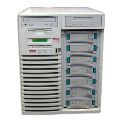
DEC
DEC AlphaServer 1000A User manual
DEC
DEC DECNIS 600 Manual
DEC
DEC AlphaServer 2100 User manual
DEC
DEC Rackmount 7000 AXP User manual
DEC
DEC Rackmount 7000 AXP Instruction Manual
