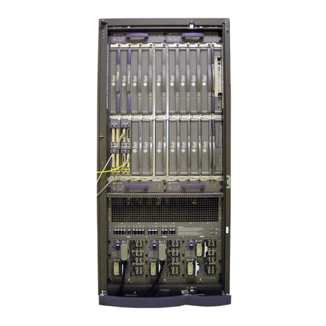
DEC AlphaServer 2100 User manual

AlphaServer2100
Owner’sGuide
Order Number: EK–KN450–OP. B01
Digital Equipment Corporation
Maynard, Massachusetts

First Printing, May 1994
Revised February 1995
Digital Equipment Corporation makes no representations that the use of its
products in the manner described in this publication will not infringe on
existing or future patent rights, nor do the descriptions contained in this
publication imply the granting of licenses to make, use, or sell equipment or
software in accordance with the description.
Possession, use, or copying of the software described in this publication
is authorized only pursuant to a valid written license from Digital or an
authorized sublicensor.
© Digital Equipment Corporation 1995. All Rights Reserved.
The postpaid Reader’s Comments forms at the end of this document request
your critical evaluation to assist in preparing future documentation.
The following are trademarks of Digital Equipment Corporation: AlphaServer,
DEC, DECconnect, Digital, OpenVMS, StorageWorks, ThinWire, VAX, VT, the
AlphaGeneration logo, and the DIGITAL logo.
OSF/1 is a registered trademark of Open Software Foundation, Inc. PostScript
is a registered trademark of Adobe Systems, Inc. UNIX is a registered
trademark in the United States and other countries licensed exclusively
through X/Open Company Ltd. Windows and Windows NT are trademarks of
Microsoft Inc.
All other trademarks and registered trademarks are the property of their
respective holders.
S2772
FCC Notice:
This equipment generates, uses, and may emit radio frequency. The equipment
has been type tested and found to comply with the limits for a Class A
digital device pursuant to Part 15 of FCC rules, which are designed to provide
reasonable protection against such radio frequency interference.
Operation of this equipment in a residential area may cause interference, in
which case the user at his own expense will be required to take whatever
measures may be required to correct the interference.
This document was prepared using VAX DOCUMENT Version 2.1.

EC:
Warning! This is a Class A product. In a domestic environment this product
may cause radio interference in which case the user may be required to take
adequate measures.
Achtung! Dieses ist ein Gerät der Funkstörgrenzwerklasse A. In
Wohnbereichen können bei Betrieb dieses Gerätes Rundfunkstörungen
auftreten, in welchen Fällen der Benutzer für entsprechende Gegenmaßnahmen
verantwortlich ist.
Attention! Ceci est un produit de Classe A. Dans un environnement
domestique, ce produit risque de créer des interférences radioeléctriques,
il appartiendra alors à l’utilisateur de prendre les mesures spécifiques
appropriées.
ACOUSTICS: Preliminary declared values per ISO 9296 and ISO 7779:
Sound Power Level
LwAd,B
Sound Pressure Level
LpAm, dBA (Bystander
Positions)
Idle 6.5 47
Operating 6.5 47
Current values for specific configurations are available from Digital
representatives. 1B=10dBA.
SCHALLEMISSIONSWERTE: Verläufige Werteangaben nach ISO 9296 und
ISO 7779/DIN EN27779:
Schalleistungspegel
LwAd,B
Schalldruckpegel
LpAm, dBA
(Zuschauerpositionen)
Leerlauf 6,5 47
Betrieb 6,5 47
Aktuelle Werte für spezielle Ausrüstungsstufen sind über die Digital Equipment
Vertretungen erhältlich. 1 B = 10 dBA.


Contents
Preface ..................................................... xiii
1 Basic Operation
Before Using this Guide . . ........................... 1–1
In This Chapter ................................... 1–2
System Features . . ................................... 1–3
Overview ........................................ 1–3
Characteristics . ................................... 1–3
Architecture . . . ................................... 1–4
Environmental and Power Requirements ................... 1–6
In This Section . ................................... 1–6
System Dimensions ................................ 1–6
Environmental Specifications ......................... 1–7
Power Requirements ............................... 1–8
Power Cords . . . ................................... 1–9
Moving the System ................................ 1–10
Repositioning the System . ........................... 1–10
Opening the System Door ........................... 1–12
Turning the System On ................................ 1–13
Overview ........................................ 1–13
Checking System Settings ........................... 1–14
Powering Up the System . ........................... 1–16
Displaying Power-Up Information . . ................... 1–18
Checking Power-Up Display .......................... 1–19
Preboot Tasks. . ................................... 1–23
Booting the Operating System ........................ 1–25
Autobooting the Operating System . ................... 1–27
Powering Down the System . . ........................... 1–27
Before You Begin .................................. 1–27
Turning Off DC Power . . . ........................... 1–28
Extended Power-Down (AC Power) . ................... 1–29
Invoking Console Mode ................................ 1–30
v

Console Subsystem. ................................ 1–30
Console Terminal . . ................................ 1–30
Console Mode ..................................... 1–30
Invoking Console Mode ............................. 1–31
Remote Access .................................... 1–31
Connecting to Networks ................................ 1–32
Overview ........................................ 1–32
Ethernet ........................................ 1–32
Connecting Peripherals ................................ 1–34
Serial/Parallel Connections . . ........................ 1–34
Terminal Connections .............................. 1–36
Operating Storage Devices .............................. 1–38
Overview ........................................ 1–38
For Additional Information . . ........................ 1–38
Before You Operate Mass Storage Devices ............... 1–38
Identifying Mass Storage Compartments ................ 1–38
Operating Storage Devices . . . ........................ 1–39
Operating a Compact Disc Drive . ........................ 1–40
Compact Disc Drive Description....................... 1–40
Caddyless Drive . . . ................................ 1–40
Drive with Caddy . . ................................ 1–42
Inserting and Removing a Compact Disc ............... 1–44
Operating a DAT Tape Drive ............................ 1–48
DAT Description. . . ................................ 1–48
Inserting a Tape . . . ................................ 1–48
Removing a Tape . . ................................ 1–48
Operating a Diskette Drive ............................. 1–50
Diskette Drive Description . . . ........................ 1–50
Inserting a Diskette ............................... 1–50
Removing a Diskette ............................... 1–50
Operating a QIC Drive . ................................ 1–52
QIC Drive Description .............................. 1–52
Inserting a QIC Tape ............................... 1–52
Removing a QIC Tape .............................. 1–52
2 Hardware Components
In This Chapter . . . ................................ 2–1
Operator Control Panel (OCP) . . . ........................ 2–2
Power-up Display . . ................................ 2–2
DC On/Off Button . ................................ 2–3
Halt Button ...................................... 2–3
Reset Button ..................................... 2–4
vi

Doors and Panels . . ................................... 2–5
Door and Panel Removal . ........................... 2–5
System Front ........................................ 2–8
Front Components ................................. 2–8
System Rear......................................... 2–10
Rear Components .................................. 2–10
System Module Locations............................... 2–12
Card Cage ....................................... 2–12
Accessing the Card Cage . ........................... 2–12
Accessories .......................................... 2–14
Accessories ....................................... 2–14
3 Options and Upgrades
In this Chapter ................................... 3–1
Upgrade Overview . ................................... 3–2
Planning Your Upgrade . . ........................... 3–2
Adding Third-Party Devices .......................... 3–3
Supported Options . ................................... 3–4
Supported Options ................................. 3–4
Access from the Internet . ........................... 3–4
Access from CompuServe . ........................... 3–4
Digital Systems and Options Catalog................... 3–4
Verifying System Configuration .......................... 3–5
Before You Begin .................................. 3–5
Firmware Menu Options for Windows NT ............... 3–5
Viewing ARC Hardware Display . . . ................... 3–5
Viewing ARC Environment Variables................... 3–8
ARC Environment Variables ......................... 3–9
For More Information . . . ........................... 3–10
Firmware Console Commands for DEC OSF/1 and
OpenVMS........................................ 3–10
show device . . . ................................... 3–13
show memory . . ................................... 3–16
Setting and Showing Environment Variables . . . .......... 3–17
System Bus Options ................................... 3–18
CPU Modules . . ................................... 3–20
Memory Modules .................................. 3–22
External I/O . . . ................................... 3–22
Standard I/O Module .................................. 3–23
EISA Bus Options . ................................... 3–24
ISA Bus Options . . ................................... 3–26
Identifying ISA and EISA Options ........................ 3–28
vii

Configuring EISA and ISA Options ....................... 3–29
EISA Configuration Utility . . ........................ 3–29
System Configuration Diskette ....................... 3–29
Before You Run the ECU ............................ 3–29
Starting the ECU . . ................................ 3–30
Configuring EISA Options .............................. 3–33
Configuring EISA/ISA Options . . . ........................ 3–35
PCI Bus Options ..................................... 3–37
Installing PCI Boards .............................. 3–38
SCSI Buses . ........................................ 3–39
Internal SCSI Bus . ................................ 3–39
Configuring the Removable Media Bus . ................ 3–40
Internal StorageWorks Shelves ....................... 3–42
Installing StorageWorks Fixed Disks . . . ................ 3–44
Guidelines for Systems with SWXCR-Ex Controller. ....... 3–46
Power Supply Configurations ............................ 3–47
Power Supply Modes ............................... 3–47
Ordering Guidelines ................................ 3–48
4 Troubleshooting the System
Introduction ...................................... 4–1
In This Chapter . . . ................................ 4–1
Before You Begin ..................................... 4–2
Determine Service Provider . . ........................ 4–2
Identifying Problems ............................... 4–3
Task Overview ....................................... 4–4
Steps to Identifying a Problem ........................ 4–4
Determining Type of Problem . . . ........................ 4–5
Types of System Problems . . . ........................ 4–5
Reporting Problems to Digital Services .................... 4–6
Pre-Call Checklist . ................................ 4–6
Digital Support Center Contact Numbers ............... 4–6
Power Problems ...................................... 4–10
Problems Getting to Console Mode ....................... 4–11
Interpreting the Operator Control Panel Power-Up Display .... 4–12
CPU Failover ..................................... 4–12
Console Reported Problems ............................. 4–15
show fru . ........................................ 4–16
test ............................................. 4–18
Mass Storage Problems Indicated at Power-Up .............. 4–20
EISA Bus Problems Indicated at Power-Up . ................ 4–23
PCI Bus Problems Indicated at Power-Up . . ................ 4–25
viii

Boot Problems ....................................... 4–26
Operating System Reported Problems . . ................... 4–28
Problems with RAID Devices . ........................... 4–29
Glossary
Index
Examples
1–1 Boot Menu Example ................................ 1–22
3–1 Sample Hardware Configuration Display ................ 3–6
3–2 ARC Environment Variable Display . ................... 3–8
Figures
1–1 System Architecture................................ 1–5
1–2 System Dimensions and Service Area .................. 1–6
1–3 Power Requirements ............................... 1–8
1–4 System Leveler Feet................................ 1–11
1–5 System Keys . . ................................... 1–12
1–6 Powered-Down System Settings ....................... 1–15
1–7 Powering Up the System . ........................... 1–17
1–8 Turning Off the System . . ........................... 1–28
1–9 Turning Off AC Power . . . ........................... 1–29
1–10 Ethernet Network Connections ....................... 1–33
1–11 Connecting Serial and Parallel Devices ................. 1–35
1–12 Terminal Connections . . . ........................... 1–37
1–13 Storage Compartments . . ........................... 1–39
1–14 Caddyless CD–ROM Drive .......................... 1–41
1–15 CD–ROM Drive with Caddy .......................... 1–43
1–16 Inserting and Removing a Caddyless Compact Disc (Internal
Disc Caddy) . . . ................................... 1–45
1–17 Inserting and Removing a CD–ROM Caddy .............. 1–47
1–18 Inserting and Removing a Tape: DAT .................. 1–49
1–19 Diskette Drive and Diskette ......................... 1–51
1–20 QIC Tape Drive and QIC Tape ........................ 1–52
ix

2–1 Operator Control Panel ............................. 2–2
2–2 Door and Panel Removal ............................ 2–6
2–3 System Front ..................................... 2–8
2–4 System Rear...................................... 2–10
2–5 System Module Locations............................ 2–13
2–6 Accessories ....................................... 2–15
3–1 Device Name Convention ............................ 3–13
3–2 System Bus Option Locations ........................ 3–19
3–3 System Bus Configurations According to Number of
CPUs . . . ........................................ 3–21
3–4 ISA and EISA Boards .............................. 3–28
3–5 PCI Board ....................................... 3–37
3–6 Removable-Media Bus Configurations . . ................ 3–41
3–7 Internal StorageWorks Configuration. . . ................ 3–42
3–8 SCSI Cable Routing to Internal StorageWorks Shelves ..... 3–43
3–9 Installing Hard-Disk Drives . . ........................ 3–45
3–10 Power Supply Configurations . ........................ 3–49
Tables
1–1 System Characteristics.............................. 1–4
1–2 Environmental Specifications . ........................ 1–7
1–3 Power Cord Order Numbers . . ........................ 1–9
1–4 Interpreting Operator Control Panel Power-Up Display .... 1–20
1–5 Booting the Operating System for the First Time . . ....... 1–25
3–1 Device Names .................................... 3–8
3–2 ARC Firmware Environment Variables . ................ 3–9
3–3 Summary of Procedure for Configuring EISA Bus (EISA
Options Only) .................................... 3–34
3–4 Summary of Procedure for Configuring EISA Bus with ISA
Options . ........................................ 3–36
3–5 RAID Subsystem Documentation ...................... 3–46
4–1 How to Identify a Problem . . . ........................ 4–3
4–2 Steps to Resolving Problems . ........................ 4–4
4–3 Problem Reference . ................................ 4–5
4–4 Digital Support Centers ............................. 4–7
4–5 Troubleshooting Power Problems ...................... 4–10
x

4–6 Troubleshooting Problems Getting to Console Mode........ 4–11
4–7 Interpreting Operator Control Panel Power-Up Display . . . . 4–14
4–8 Troubleshooting Console Reported Problems . . . .......... 4–15
4–9 Troubleshooting Fixed-Media Problems ................. 4–20
4–10 Troubleshooting Removable-Media Problems . . . .......... 4–22
4–11 Troubleshooting EISA Problems ....................... 4–24
4–12 Troubleshooting PCI Problems ........................ 4–25
4–13 Troubleshooting Boot Problems ....................... 4–26
4–14 Troubleshooting Operating System Reported Errors ....... 4–28
4–15 Troubleshooting RAID Problems . . . ................... 4–29
xi


Preface
Purpose of This
Guide This guide describes how to operate, troubleshoot, and maintain
the AlphaServer 2100 4/xxx or 5/xxx system.
Online
Information Your system shipment includes a set of diskettes called the
‘‘Fast Track to Information.’’ Fast Track is an easy-to-navigate,
electronic version of the information in this owner’s guide
and the information in the AlphaServer 2000/2100 Firmware
Reference Guide.
You can install Fast Track on any personal computer or laptop
computer running Microsoft Windows V3.1 or later or a Windows
emulator. You need to have approximately four megabytes
available on your designated disk.
xiii
Before You Use
This Guide This guide assumes that you are ready to operate your system.
Before using this guide, a qualified service person should install
the system at your site.
Caution
Only qualified service persons should install the system.
Qualified service persons need not be Digital service
representatives, but they should have the technical
training and experience necessary:
• To be aware of physical hazards to which they are
exposed in performing a task.
• To take measures to minimize danger to themselves
and other persons.
Books Used
with This Guide If you have not installed the system, refer to the Basic
Installation document shipped with the system.
Some procedures, such as the boot procedure, require you
to refer to your operating system documentation. Please
have your operating system installation documentation
and related ‘‘Read Me First’’ documents or release notes
available for use with this guide.
You will also need to become familiar with the console
firmware interfaces that facilitate interaction between
the server hardware and the operating system. The
AlphaServer 2000/2100 Firmware Reference Guide was
included in your system shipment. Be sure to consult that
guide as needed.
Who Should
Use This Guide This book is for system managers and others who perform system
management tasks.
xiv

Structure of
This Guide This guide contains information about how to use your system to
best advantage:
• Chapter 1 introduces the system and describes basic system
management tasks.
• Chapter 2 describes system components and their functions.
• Chapter 3 describes how to identify your system
configuration and how to change your configuration.
• Chapter 4 explains how to identify and resolve problems that
may prevent the system from operating correctly.
• The Glossary defines technical terms related to the
AlphaServer 2100 system.
Warning
Symbols This symbol indicates components that become
extremely hot.
This symbol indicates a potential hazard of which you
should be aware.
For More
Information You may find it useful to have your operating system
documentation and your system hardware documentation on
hand for use with this guide.
You can download up-to-date files and information for managing
the AlphaServer 2100 system from the Internet.
Via FTP on ftp.digital.com. Once connected, go to:
/pub/Digital/Alpha/systems
Via World Wide Web:
http://www.service.digital.com/alpha/server/
The information includes firmware updates, the latest
configuration utilities, software patches, a list of supported
options, and more. There are no restrictions on accessing and
downloading these files.
xv

Firmware
Updates Under some circumstances, such as a CPU upgrade, you
may need to update your firmware. Firmware updates are
shipped quarterly on CD–ROM for the DEC OSF/1 and
OpenVMS operating systems. Firmware updates for DEC OSF/1,
OpenVMS, and Windows NT are also available on the Internet,
as noted above.
Conventions The following table lists conventions used in this guide.
Convention Meaning
Return A key name enclosed in a box indicates that you press that key.
Ctrl/xCtrl/xindicates that you hold down the Ctrl key while you
press another key, indicated here by x. In examples, this key
combination is enclosed in a box, for example,Ctrl/C .
lowercase Lowercase letters in commands indicate that commands can be
entered in uppercase or lowercase.
Warning Warnings contain information to prevent personal injury.
Caution Cautions provide information to prevent damage to equipment
or software.
[]
In command format descriptions, brackets indicate optional
elements.
console command
abbreviations Console command abbreviations must be entered exactly as
shown.
boot
Console and operating system commands are shown in this
special typeface.
italic type Italic type in console command sections indicates a variable.
< > In console mode online help, angle brackets enclose a
placeholder for which you must specify a value.
{ } In command descriptions, braces containing items separated by
commas imply mutually exclusive items.
!"#
. . . In figures, a numbered callout labels a part of the figure. In
text, it refers to a labeled part of a corresponding figure.
xvi
1
Basic Operation
Before Using
this Guide If you have not installed the system, refer to the Basic
Installation document shipped with the system.
Some procedures, such as the boot procedure, require you
to refer to your operating system documentation. Please
have your operating system installation documentation
and related ‘‘Read Me First’’ documents or release notes
available for use with this guide.
You will also need to become familiar with the console
firmware interfaces that facilitate interaction between
the server hardware and the operating system. The
AlphaServer 2000/2100 Firmware Reference Guide was
included in your system shipment. Be sure to consult that
guide as needed.
Basic Operation 1–1

Basic Operation
In This Chapter This chapter covers the following information:
• System Features
• Environmental and Power Requirements
• Turning the System On
• Powering Down the System
• Invoking Console Mode
• Connecting to Networks
• Connecting to Peripherals
• Operating Storage Devices
1–2 Basic Operation

System Features
System Features
Overview A powerful symmetric multiprocessing (SMP) server, the
AlphaServer 2100 4/xxx or 5/xxx pedestal system offers
departmental computing power and capabilities in a pedestal
package. The system is based on Digital’s 64-bit, Alpha RISC
architecture, which provides fast processing and quick response
for advanced applications.
The system resides in the BA740 pedestal enclosure. The system
is designed for office environments where a compact footprint
and low to medium disk storage capacities are required. It
supports up to four CPUs, providing SMP, industry-standard PCI
and EISA I/O, and up to 32 gigabytes of in-cabinet storage (200
gigabytes total). Up to 2 gigabytes of high-capacity memory will
be available.
Characteristics Table 1–1 highlights some key characteristics of the system.
Basic Operation 1–3

System Features
Table 1–1 System Characteristics
Characteristic Description
Four–processor capability System can be configured as a uniprocessor or with up
to four processors.
High-performance PCI I/O
subsystem PCI is the emerging industry-standard bus that
supports Digital and third-party options.
The current implementation of PCI on the server has a
peak bandwidth of 132 MB/sec.
EISA I/O bus 33 MB/sec EISA I/O bus supports industry standard
EISA options, such as:
Network adapters
Video/audio options
Storage adapters
Flexible mass storage
strategy StorageWorks compatible storage devices for low-cost,
high-capacity flexible configurations
3.5-in. storage devices Up to 16, 3.5-in. high performance disk drives may be
configured in the BA740 pedestal enclosure, providing
many independent disks that may be configured in
stripe sets, shadow sets, or RAID sets to optimize
performance according to customer requirements.
High availability With the optional RAID controller, the system supports
disk hot swap in StorageWorks shelves with the
operating systems as well as clustering.
Optional dual power supply provides N+1 redundancy.
All models except model 4/200 support CPU failover.
CPU chip technology The Alpha chip is manufactured using Digital’s state-
of-the-art CMOS process.
CPU chip design features Superscalar, superpipelined.
System bus bandwidth 667 MB/sec (128-bit, 24-ns cycle.)
Memory Up to two gigabytes of main memory will be supported.
Architecture Figure 1–1 illustrates the server system architecture.
1–4 Basic Operation
Other manuals for AlphaServer 2100
1
Table of contents
Other DEC Server manuals

DEC
DEC 4000 Model 200 User manual

DEC
DEC Digital AlphaServer 400 series Operation manual

DEC
DEC 4000 AXP User manual

DEC
DEC VAX 4000 300 User manual

DEC
DEC Rackmount 7000 AXP Instruction Manual

DEC
DEC AlphaServer 8200 User manual

DEC
DEC AlphaServer 8200 User manual

DEC
DEC AlphaServer 1000A User manual

DEC
DEC DECNIS 600 Manual

DEC
DEC 3000 Model 400S Operating instructions
Popular Server manuals by other brands

NEC
NEC Express5800/120Rh-2 Getting started guide

HP
HP 3000/9x9KS Series Site preparation and requirements guide

Russound
Russound SMS3 user guide

Cisco
Cisco 7835-H2 - Media Convergence Server datasheet

IBM
IBM System x3250 M3 Type 4251 Product guide

Intel
Intel SR1680MV - Server System - 0 MB RAM Service guide