DEC VAX 4000 300 User manual

VAX 4000 Model 300
Operation
Order Number EK–336AC–OP–003
Digital Equipment Corporation
Maynard, Massachusetts

First Printing, March 1990
Revised, July 1990
Revised, June 1991
The information in this document is subject to change without notice and should not be
construed as a commitment by Digital Equipment Corporation.
Digital Equipment Corporation assumes no responsibility for any errors that may appear in
this document.
The software, if any, described in this document is furnished under a license and may be used
or copied only in accordance with the terms of such license. No responsibility is assumed
for the use or reliability of software or equipment that is not supplied by Digital Equipment
Corporation or its affiliated companies.
Restricted Rights: Use, duplication or disclosure by the U.S. Government is subject to
restrictions as set forth in subparagraph (c)(1)(ii) of the Rights in Technical Data and Computer
Software clause at DFARS 252.227–7013.
© Digital Equipment Corporation, 1991. All rights reserved.
Printed in U.S.A.
The Reader’s Comments form at the end of this document requests your critical evaluation to
assist in preparing future documentation.
The following are trademarks of Digital Equipment Corporation: CompacTape, CX, DDCMP,
DEC, DECconnect, DECdirect, DECnet, DECscan, DECserver, DECUS, DECwindows,
DELNI, DEMPR, DESQA, DESTA, DSRVB, DSSI, IVAX, KDA, KLESI, KRQ50, MicroVAX,
MSCP, Q-bus, Q22-bus, RA, RQDX, RV20, SA, SDI, ThinWire, TK, TMSCP, TQK, TS05, TU,
VAX, VAX 4000, VAXcluster, VAX DOCUMENT, VAXELN, VAXlab, VAXserver, VMS, VT, and
the DIGITAL logo.
X Window System is a trademark of Massachusetts Institute of Technology.
FCC NOTICE: The equipment described in this manual generates, uses, and may emit radio
frequency energy. The equipment has been type tested and found to comply with the limits for
a Class A computing device pursuant to Subpart J of Part 15 of FCC Rules, which are designed
to provide reasonable protection against such radio frequency interference when operated in
a commercial environment. Operation of this equipment in a residential area may cause
interference, in which case the user at his own expense may be required to take measures to
correct the interference.
S1679
This document was prepared using VAX DOCUMENT, Version 1.2.

Contents
Preface ix
Chapter 1 System Overview
1.1 Front View and Physical Description . . . . . . . . . . . . . . . . . . . 1–1
1.1.1 BA440 Enclosure . . . . . . . . . . . . . . . . . . . . . . . . . . . . . . . . 1–6
1.1.1.1 Mass Storage Shelf . . . . . . . . . . . . . . . . . . . . . . . . . . . . 1–8
1.1.1.2 CardCage ................................... 1–10
1.1.1.3 Console Module . . . . . . . . . . . . . . . . . . . . . . . . . . . . . . . 1–11
1.1.1.4 DSSI Connector (DSSI Bus 0) . . . . . . . . . . . . . . . . . . . . 1–14
1.1.1.5 Power Supply Controls and Indicators . . . . . . . . . . . . . . 1–15
1.1.1.6 Fans........................................ 1–18
1.2 Functional Description of Base System . . . . . . . . . . . . . . . . . 1–19
1.2.1 Base System Components . . . . . . . . . . . . . . . . . . . . . . . . . 1–19
1.2.1.1 Central Processing Unit (CPU) . . . . . . . . . . . . . . . . . . . 1–20
1.2.1.2 Console Serial Line Unit (SLU) . . . . . . . . . . . . . . . . . . . 1–20
1.2.1.3 MainMemory................................. 1–20
1.2.1.4 Network Controller . . . . . . . . . . . . . . . . . . . . . . . . . . . . 1–20
1.2.1.5 Embedded DSSI Host Adapters . . . . . . . . . . . . . . . . . . . 1–21
1.2.2 Optional Components . . . . . . . . . . . . . . . . . . . . . . . . . . . . . 1–21
1.2.2.1 Mass Storage Devices and Controllers . . . . . . . . . . . . . . 1–21
1.2.2.2 Mass Storage Subsystems . . . . . . . . . . . . . . . . . . . . . . . 1–22
1.2.2.3 Mass Storage Expanders . . . . . . . . . . . . . . . . . . . . . . . . 1–22
1.2.2.4 Communications Controllers . . . . . . . . . . . . . . . . . . . . . 1–23
1.2.2.5 Real-Time Controllers . . . . . . . . . . . . . . . . . . . . . . . . . . 1–25
1.2.2.6 Printer Interfaces . . . . . . . . . . . . . . . . . . . . . . . . . . . . . . 1–25
1.2.2.7 Other Available Options . . . . . . . . . . . . . . . . . . . . . . . . . 1–25
1.3 Dual-Host Capability (VMS Systems Only) . . . . . . . . . . . . . . 1–25
iii

Chapter 2 Operating the System
2.1 Before You Operate the System . . . . . . . . . . . . . . . . . . . . . . . 2–1
2.2 SwitchSettings ................................... 2–1
2.2.1 Normal Operation . . . . . . . . . . . . . . . . . . . . . . . . . . . . . . . 2–1
2.2.2 Special Operation . . . . . . . . . . . . . . . . . . . . . . . . . . . . . . . . 2–2
2.3 Turning On the System . . . . . . . . . . . . . . . . . . . . . . . . . . . . . 2–4
2.4 Booting the System . . . . . . . . . . . . . . . . . . . . . . . . . . . . . . . . 2–6
2.4.1 Autobooting the System . . . . . . . . . . . . . . . . . . . . . . . . . . . 2–6
2.4.2 Booting the System from Console Mode . . . . . . . . . . . . . . . 2–11
2.5 UsingtheSystem.................................. 2–12
2.6 Halting the System . . . . . . . . . . . . . . . . . . . . . . . . . . . . . . . . 2–12
2.7 Restarting the System . . . . . . . . . . . . . . . . . . . . . . . . . . . . . . 2–13
2.8 Turning Off the System . . . . . . . . . . . . . . . . . . . . . . . . . . . . . 2–13
2.9 Recovering from an Over Temperature Condition . . . . . . . . . 2–14
Chapter 3 Operating the System Options
3.1 Mass Storage Options . . . . . . . . . . . . . . . . . . . . . . . . . . . . . . 3–1
3.1.1 RF-Series Integrated Storage Elements . . . . . . . . . . . . . . . 3–2
3.1.1.1 RF-Series Controls and Indicators . . . . . . . . . . . . . . . . . 3–2
3.1.1.2 Changing the Bus Node ID Plugs . . . . . . . . . . . . . . . . . 3–5
3.1.2 TF85TapeDrive ................................ 3–6
3.1.2.1 Design of the Drive . . . . . . . . . . . . . . . . . . . . . . . . . . . . 3–8
3.1.2.2 Labeling a Tape Cartridge . . . . . . . . . . . . . . . . . . . . . . . 3–8
3.1.2.3 Write-Protecting a Tape Cartridge . . . . . . . . . . . . . . . . . 3–9
3.1.2.4 Tape Cartridge Handling and Storage Guidelines . . . . . 3–12
3.1.2.5 Inserting a Tape Cartridge . . . . . . . . . . . . . . . . . . . . . . . 3–12
3.1.2.6 Removing a Tape Cartridge . . . . . . . . . . . . . . . . . . . . . . 3–15
3.1.2.7 Summary of TF85 Tape Drive Controls and Indicators . 3–17
3.1.2.8 Cleaning the TF85 Tape . . . . . . . . . . . . . . . . . . . . . . . . . 3–18
3.1.3 TK70 Tape Drive . . . . . . . . . . . . . . . . . . . . . . . . . . . . . . . . 3–18
3.1.3.1 Design of the Drive . . . . . . . . . . . . . . . . . . . . . . . . . . . . 3–20
3.1.3.2 Labeling a Tape Cartridge . . . . . . . . . . . . . . . . . . . . . . . 3–21
3.1.3.3 Write-Protecting a Tape Cartridge . . . . . . . . . . . . . . . . . 3–22
3.1.3.4 Tape Cartridge Handling and Storage Guidelines . . . . . 3–24
3.1.3.5 Inserting a Tape Cartridge . . . . . . . . . . . . . . . . . . . . . . . 3–24
iv

3.1.3.6 Removing a Tape Cartridge . . . . . . . . . . . . . . . . . . . . . . 3–27
3.1.3.7 Summary of TK70 Tape Drive Controls and Indicator
Lights....................................... 3–29
3.1.4 TLZ04 Tape Drive . . . . . . . . . . . . . . . . . . . . . . . . . . . . . . . 3–30
3.1.4.1 Proper Handling of Cassette Tapes . . . . . . . . . . . . . . . . 3–32
3.1.4.2 Setting the Write-Protect Tab on the Cassette Tape . . . . 3–33
3.1.4.3 Inserting a Cassette Tape into the Drive . . . . . . . . . . . . 3–34
3.1.4.4 System Software . . . . . . . . . . . . . . . . . . . . . . . . . . . . . . 3–35
3.1.4.5 Cleaning the Heads . . . . . . . . . . . . . . . . . . . . . . . . . . . . 3–36
3.1.5 RV20 Optical Disk Subsystem . . . . . . . . . . . . . . . . . . . . . . 3–37
3.1.6 RRD40-Series Compact Disc Drive Subsystem . . . . . . . . . . 3–38
3.1.7 TSV05 Tape Drive . . . . . . . . . . . . . . . . . . . . . . . . . . . . . . . 3–38
3.1.8 TSZ07 Tape Drive . . . . . . . . . . . . . . . . . . . . . . . . . . . . . . . 3–38
3.1.9 TU81E Tape Drive . . . . . . . . . . . . . . . . . . . . . . . . . . . . . . . 3–38
3.2 Communications Controller Options . . . . . . . . . . . . . . . . . . . 3–38
3.2.1 Asynchronous Serial Controllers . . . . . . . . . . . . . . . . . . . . 3–38
3.2.1.1 Asynchronous Controllers Without Modem Support . . . . 3–39
3.2.1.2 Asynchronous Controllers With Modem Support . . . . . . 3–40
3.2.2 Synchronous Controllers . . . . . . . . . . . . . . . . . . . . . . . . . . 3–40
3.2.3 Network Controllers . . . . . . . . . . . . . . . . . . . . . . . . . . . . . . 3–41
3.3 Real-Time Options . . . . . . . . . . . . . . . . . . . . . . . . . . . . . . . . . 3–42
3.4 PrinterOptions ................................... 3–43
3.5 AddingOptions ................................... 3–43
Appendix A Related Documentation
Appendix B Programming Parameters for DSSI Devices
B.1 DSSI Device Parameters . . . . . . . . . . . . . . . . . . . . . . . . . . . . B–1
B.2 How VMS Uses the DSSI Device Parameters . . . . . . . . . . . . B–3
B.3 Examining and Setting DSSI Device Parameters . . . . . . . . . . B–4
B.3.1 Entering the DUP Driver Utility . . . . . . . . . . . . . . . . . . . . B–8
B.3.2 Setting Allocation Class . . . . . . . . . . . . . . . . . . . . . . . . . . . B–9
B.3.3 Setting Unit Number . . . . . . . . . . . . . . . . . . . . . . . . . . . . . B–10
B.3.4 Setting Node Name . . . . . . . . . . . . . . . . . . . . . . . . . . . . . . B–13
B.3.5 Setting System ID . . . . . . . . . . . . . . . . . . . . . . . . . . . . . . . B–13
v

B.3.6 Exiting the DUP Server Utility . . . . . . . . . . . . . . . . . . . . . B–14
Appendix C Backup Procedures
C.1 Overview of Standalone BACKUP . . . . . . . . . . . . . . . . . . . . . C–1
C.1.1 Installing Standalone BACKUP on the System Disk . . . . . C–2
C.1.2 Booting Standalone BACKUP from the System Disk . . . . . C–2
C.1.3 Installing Standalone BACKUP on a Tape Cartridge . . . . . C–3
C.1.4 Booting Standalone BACKUP from a Tape Cartridge . . . . C–5
C.2 Backing Up the System Disk . . . . . . . . . . . . . . . . . . . . . . . . . C–6
C.3 Restoring the System Disk . . . . . . . . . . . . . . . . . . . . . . . . . . . C–9
Appendix D Removing Unwanted VMS Files
D.1 UsingVMSTAILOR ................................ D–1
Glossary
Index
Examples
B–1 SHOW DSSI Display (Embedded DSSI) . . . . . . . . . . . . . . . . . B–7
B–2 SHOW UQSSP Display (KFQSA-Based DSSI) . . . . . . . . . . . . B–8
B–3 Starting the DUP Driver Utility (Embedded DSSI) . . . . . . . . B–9
B–4 Starting the DUP Driver Utility (KFQSA-Based DSSI) . . . . . B–9
B–5 Setting Allocation Class for a Specified Device . . . . . . . . . . . B–10
B–6 Setting a Unit Number for a Specified Device . . . . . . . . . . . . B–11
B–7 Changing a Node Name for a Specified Device . . . . . . . . . . . . B–13
B–8 Changing a System ID for a Specified Device . . . . . . . . . . . . B–14
B–9 Exiting the DUP Driver Utility for a Specified Device . . . . . . B–15
B–10 SHOW DSSI Display . . . . . . . . . . . . . . . . . . . . . . . . . . . . . . . B–15
B–11 SHOW UQSSP Display (KFQSA-Based DSSI) . . . . . . . . . . . . B–16
vi

Figures
1–1 VAX4000System.................................. 1–2
1–2 KeyPositions..................................... 1–3
1–3 UpperDoorOpened................................ 1–4
1–4 Entire Door Opened . . . . . . . . . . . . . . . . . . . . . . . . . . . . . . . . 1–5
1–5 Front View of the BA440 Enclosure . . . . . . . . . . . . . . . . . . . . 1–7
1–6 Mass Storage Shelf . . . . . . . . . . . . . . . . . . . . . . . . . . . . . . . . 1–8
1–7 CardCage ....................................... 1–10
1–8 Console Module Controls and Connectors . . . . . . . . . . . . . . . 1–12
1–9 Connector for DSSI Bus 0 . . . . . . . . . . . . . . . . . . . . . . . . . . . 1–15
1–10 Power Supply Controls and Indicators . . . . . . . . . . . . . . . . . . 1–16
1–11 Sample Power Bus Configuration . . . . . . . . . . . . . . . . . . . . . . 1–18
1–12 System Air Circulation . . . . . . . . . . . . . . . . . . . . . . . . . . . . . . 1–19
1–13 Dual-Host Configuration . . . . . . . . . . . . . . . . . . . . . . . . . . . . 1–27
2–1 Language Selection Menu . . . . . . . . . . . . . . . . . . . . . . . . . . . 2–3
2–2 Sample Error Summary . . . . . . . . . . . . . . . . . . . . . . . . . . . . . 2–6
2–3 Successful Power-Up and Automatic Boot . . . . . . . . . . . . . . . 2–7
2–4 Successful Power-Up to List of Bootable Devices . . . . . . . . . . 2–7
2–5 Selecting a Bootable Device . . . . . . . . . . . . . . . . . . . . . . . . . . 2–8
2–6 Sample SHOW DEVICE Display . . . . . . . . . . . . . . . . . . . . . . 2–10
2–7 Successful Power-Up to Console Mode . . . . . . . . . . . . . . . . . . 2–11
3–1 RF-Series ISE Controls and Indicators . . . . . . . . . . . . . . . . . 3–3
3–2 Inserting Bus Node ID Plugs . . . . . . . . . . . . . . . . . . . . . . . . . 3–5
3–3 TF85TapeDrive .................................. 3–7
3–4 Labeling a Tape Cartridge . . . . . . . . . . . . . . . . . . . . . . . . . . . 3–9
3–5 Tape Cartridge Write-Protect Switch . . . . . . . . . . . . . . . . . . . 3–11
3–6 Inserting a Tape Cartridge . . . . . . . . . . . . . . . . . . . . . . . . . . . 3–14
3–7 Removing a Tape Cartridge . . . . . . . . . . . . . . . . . . . . . . . . . . 3–16
3–8 TK70TapeDrive .................................. 3–20
3–9 Labeling a Tape Cartridge . . . . . . . . . . . . . . . . . . . . . . . . . . . 3–21
3–10 Tape Cartridge Write-Protect Switch . . . . . . . . . . . . . . . . . . . 3–23
3–11 Inserting a Tape Cartridge . . . . . . . . . . . . . . . . . . . . . . . . . . . 3–26
3–12 Removing a Tape Cartridge . . . . . . . . . . . . . . . . . . . . . . . . . . 3–28
3–13 TLZ04TapeDrive ................................. 3–31
3–14 Setting the Write-Protect Tab on the Cassette Tape . . . . . . . . 3–34
3–15 Inserting a Cassette Tape into the Drive . . . . . . . . . . . . . . . . 3–35
vii

3–16 Inserting the Head Cleaning Cassette . . . . . . . . . . . . . . . . . . 3–37
B–1 VMS Operating System Requires Unique Unit Numbers for
DSSIDevices..................................... B–4
B–2 Sample DSSI Busses for an Expanded VAX 4000 Model 300
System.......................................... B–5
B–3 Attaching a Unit Number Label to the Device Front Panel . . B–12
Tables
2–1 Normal Power-Up Indications . . . . . . . . . . . . . . . . . . . . . . . . 2–4
2–2 DeviceNames .................................... 2–10
3–1 RF-Series Controls and Indicators . . . . . . . . . . . . . . . . . . . . . 3–4
3–2 Read/Write Cartridge Compatibility with the TF85 Tape
Drive ........................................... 3–6
3–3 TF85 Tape Drive Controls . . . . . . . . . . . . . . . . . . . . . . . . . . . 3–17
3–4 TF85 Tape Drive Indicators . . . . . . . . . . . . . . . . . . . . . . . . . . 3–17
3–5 TK70 Tape Drive Controls . . . . . . . . . . . . . . . . . . . . . . . . . . . 3–29
3–6 TK70 Tape Drive Indicator Lights . . . . . . . . . . . . . . . . . . . . . 3–29
3–7 TLZ04 Drive Indicators (Normal Conditions) . . . . . . . . . . . . . 3–32
3–8 TLZ04 Drive Indicators (Abnormal Conditions) . . . . . . . . . . . 3–32
C–1 Standalone BACKUP Qualifiers . . . . . . . . . . . . . . . . . . . . . . . C–7
viii

Preface
This manual describes how to use VAX 4000 Model 300 timesharing and
VAXserver 4000 Model 300 server systems. The hardware and software
for each of these systems differs slightly, according to the function of the
system. The VAX 4000 is a multiuser system that uses the VMS operating
system. The VAXserver 4000 system is a single-user system that uses VMS
or VAXELN operating systems. Both systems can function as an end- or
full-function node on an Ethernet network.
The manual is structured as follows:
• Chapter 1 provides an overview of the systems.
• Chapter 2 describes how to use each system.
• Chapter 3 describes how to use options installed in the systems.
• Appendix A lists related documentation.
• Appendix B describes how to set and examine DSSI device parameters
from console mode.
• Appendix C describes procedures for creating backup files.
• Appendix D describes how to use VMSTAILOR to remove unwanted
VMS files from the system disk.
• A glossary explains key terms.
NOTE: VAXserver systems are designed to offer maximum performance for
applications that do not require timesharing. Some of the devices referred to
in this manual are designed for multiuser systems and may not be suitable
for server systems. Contact your Digital service representative if you have
any questions about whether use of a specific device is appropriate for your
server system.
ix

Conventions
The following conventions are used in this manual:
Convention Meaning
Key A symbol denoting a terminal key used in text and examples in this book.
For example, Break indicates that you press the Break key on your terminal
keypad. Return indicates that you press the Return key on your terminal
keypad.
Ctrl/C A symbol indicating that you hold down the Ctrl key while you press the
C key.
BOLD This bold type indicates user input. For example:
>>>BOOT MUA0
This line shows that the user must enter BOOT MUA0 at the console
prompt.
NOTE Provides general information about the current topic.
CAUTION Provides information to prevent damage to equipment or software.
WARNING Provides information to prevent personal injury.
x

Chapter 1
System Overview
VAX 4000 systems house all components in a BA440 enclosure. This
enclosure is a free-standing pedestal that houses the following:
• Card cage
• System controls
• Central processing unit (CPU) module
• Memory modules
• Communications controller modules
• Tape drive controller module
• Console module
• RF-series Integrated Storage Elements
• TF85, TK70, or TLZ04 tape drive
• Power supply
• Fans
Up to four RF-series Integrated Storage Elements (ISEs) or three RF-series
ISEs and a tape drive can be mounted inside the BA440 enclosure.
This chapter describes the VAX 4000 system components and their
functions.
Chapters 2 and 3 describe how to use the system and options.
1.1 Front View and Physical Description
The front of the system has a divided door that restricts access to the system
controls. Figure 1–1 shows the system with the front door closed.
System Overview 1–1

Figure 1–1: VAX 4000 System
MLO-004032
A three-position rotary lock allows you to lock both the upper and lower
doors, or to lock just the lower door. Opening the upper door allows you to
access the controls for the RF-series Integrated Storage Elements (ISEs),
tape drive, and the System Control Panel (SCP). Opening the entire door
allows you to access all system controls and cable connections.
1–2 VAX 4000 Model 300 Operation
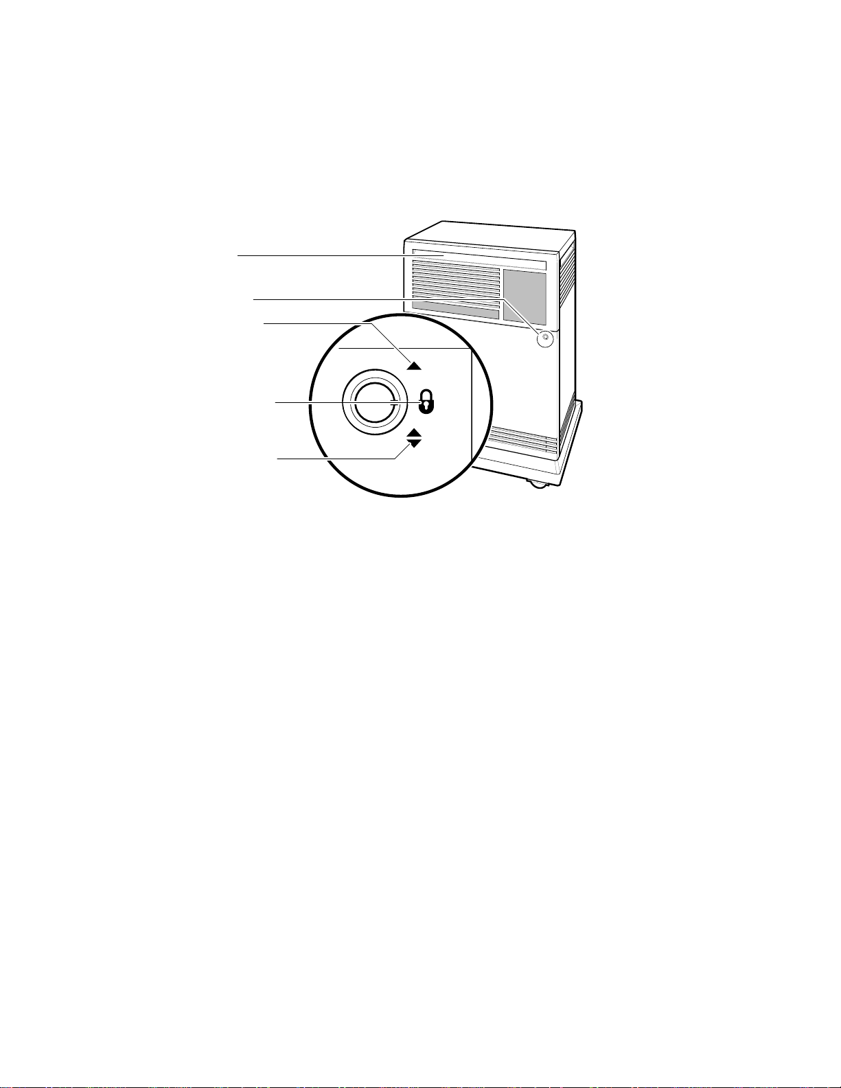
Figure 1–2 shows the three key positions and the controls accessible in each
position.
Figure 1–2: Key Positions
Tape Drive Controls and
Door Handle
(Both Doors) MLO-004958
Middle Key Position:
No Access to Controls
Bottom Key Position:
Access to Power Switch;
All Controls and Indicators
Top Key Position:
Access to SCP, ISEs, and
Rotary Key Lock
Indicators (Upper Door)
Opening and Closing the Divided Door
The divided door allows you to access the mass storage devices and system
control panel (SCP), while restricting access to the power switch and the
console module. Open and close the door as follows:
1. Insert the key in the lock on the front door. Turn the key to the top
position to open just the upper portion of the door, or to the bottom
position to open the entire door.
With the key in the bottom position, the upper and lower portions of
the door will open together.
2. Swing the door open.
3. To close the door, simply reverse the procedure. When pushing the
doors closed, push gently at the top right of the upper door and the
bottom right of the lower door.
System Overview 1–3
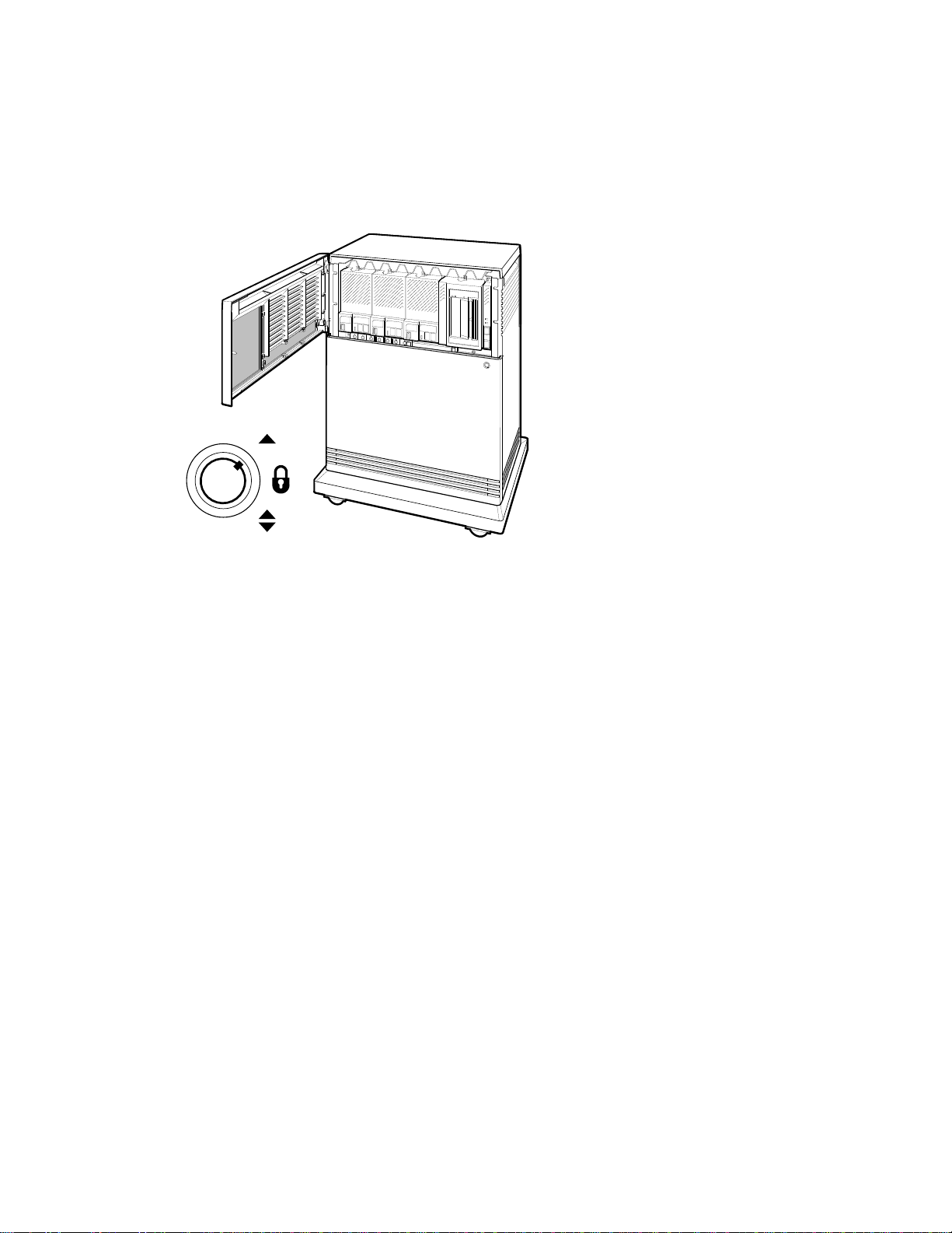
Figure 1–3 shows the system with the upper portion of the door opened.
Figure 1–3: Upper Door Opened
MLO-004034
Top Key Position
1–4 VAX 4000 Model 300 Operation
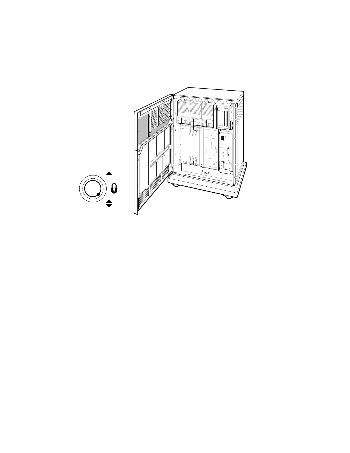
Figure 1–4 shows the system with the entire door opened.
Figure 1–4: Entire Door Opened
MLO-004035
Bottom Key Position
The next section describes the BA440 enclosure, which is exposed when you
open the entire door.
System Overview 1–5

1.1.1 BA440 Enclosure
Opening the front door enables you to access the components housed in the
BA440 enclosure. Figure 1–5 shows a typical configuration.
The BA440 enclosure can contain the following:
• Mass storage — TF85, TK70, or TLZ04 tape drive and up to three RF-
series Integrated Storage Elements (ISEs), or four RF-series ISEs and
no tape drive
All VAX 4000 systems contain the following:
• System control panel (SCP)
• Card cage containing modules — CPU, memory, communications
controllers, mass storage controllers
• Console module
• Power supply
• Fans
1–6 VAX 4000 Model 300 Operation
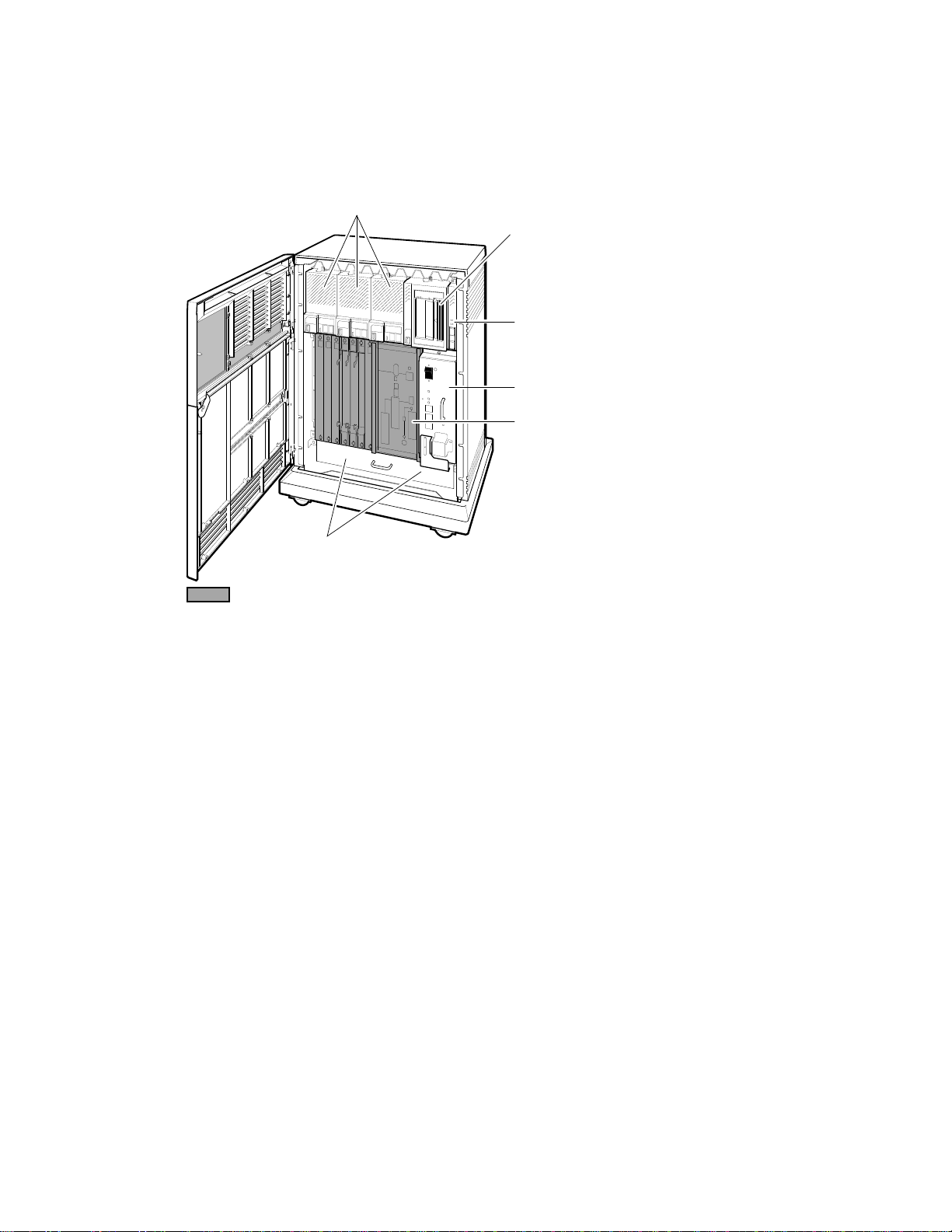
Figure 1–5: Front View of the BA440 Enclosure
System Control
Power Supply
Integrated Storage Elements (ISEs)
Card Cage
MLO-004016
Tape Drive
Panel (SCP)
Console Module
Fans
System Overview 1–7
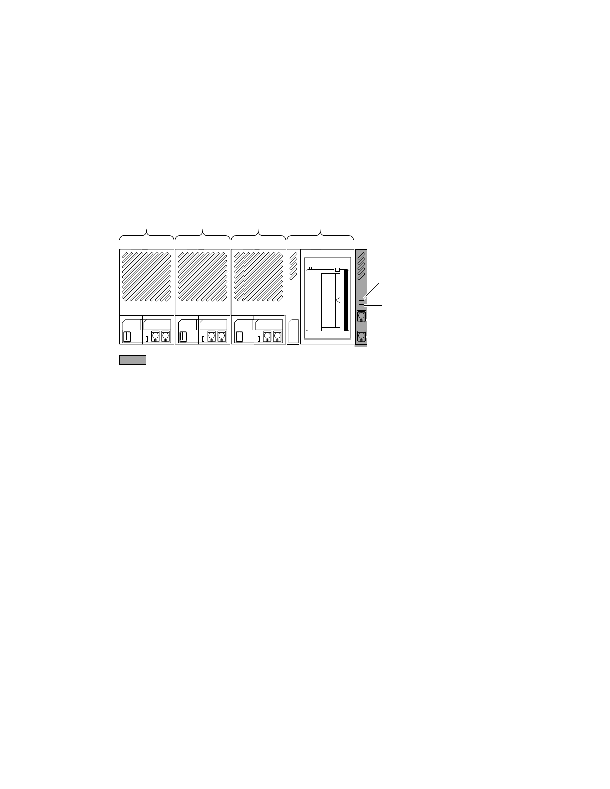
1.1.1.1 Mass Storage Shelf
The mass storage shelf extends across the top of the enclosure. The shelf
contains a system control panel (SCP), tape drive, and up to three RF-series
ISEs (tapeless systems can have up to four RF-series ISEs). Each ISE has
its own panel with controls and indicators. Instructions for using ISEs and
the TF85, TK70, or TLZ04 tape drive are in Chapter 3. The SCP is to the
right of the storage devices. Figure 1–6 shows the mass storage shelf.
Figure 1–6: Mass Storage Shelf
ISE 2 ISE 1 ISE 0 Tape Drive
MLO-005386
System Control Panel (SCP)
DC OK Indicator
Over Temperature
Warning Indicator
Halt Button
Restart Button
The SCP has two indicators: the Over Temperature Warning light and the
DC OK indicator. The red Over Temperature Warning indicator flashes to
indicate that the system’s internal temperature is approaching a level that
may cause system components to overheat. In addition to the flashing Over
Temperature Warning light, an audible alarm also provides warning of a
possible over temperature condition. If the components continue to heat,
the system will automatically shut down to prevent components from being
damaged. Chapter 2 provides instruction for turning on the system after a
preventive shutdown due to overheat conditions.
The green DC OK indicator shows that the power supply voltages are within
the correct operating range. If the DC OK indicator is not lit when the
system power is on, refer to the VAX 4000 Troubleshooting and Diagnostics
manual included in the Customer Hardware Information Kit.
Below the indicators are the Halt and Restart buttons. The Halt button is
a two-position button. When you press the button, the system halts. A red
indicator on the Halt button lights when the button is set to the in position.
Before you can enter console commands, press the Halt button again to
1–8 VAX 4000 Model 300 Operation

return it to the out position. When the Halt button is returned to the out
position, the console mode prompt >>> is displayed on the console terminal
screen. Now you can enter console commands. If you inadvertently press
the Halt button, type ‘‘c Return ’’ to continue. Chapter 2 describes halting the
system in more detail.
CAUTION: Pressing the Halt button halts the system regardless of the
setting of the Break Enable/Disable switch on the console module.
Below the Halt button is the Restart button. The Restart button has a
green indicator. When you press the Restart button, the system returns to
a power-up condition and self-tests are run. If you have specified a device
as the boot device and if the Break/Enable Disable switch is set to disable,
the system will reboot system software. Further instructions on restarting
your system are in Chapter 2.
NOTE: The Halt and Restart buttons can be disabled to prevent accidental
activation. Contact your Digital service representative if you want to disable
the controls on the SCP.
System Overview 1–9
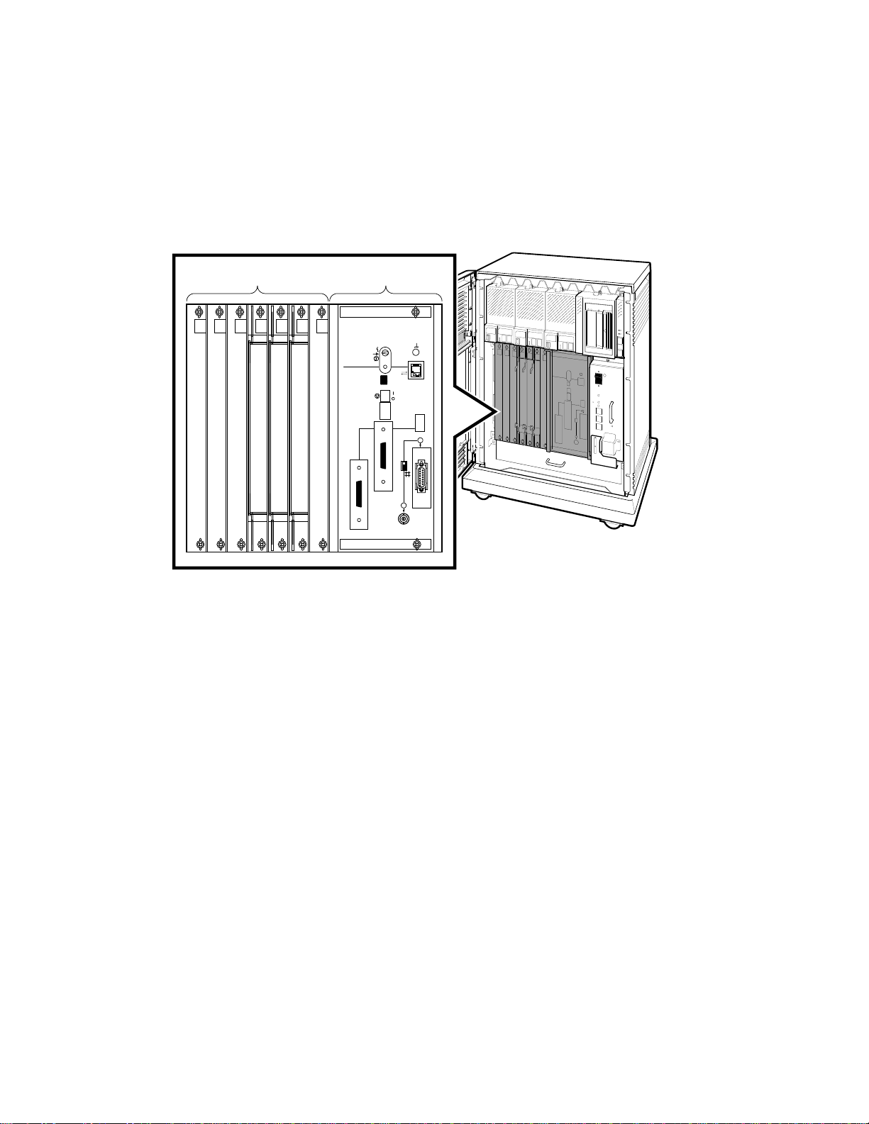
1.1.1.2 Card Cage
The modules in your system are mounted in a 12-slot card cage under the
mass storage shelf, as shown in Figure 1–7.
Figure 1–7: Card Cage
MLO-004037
Baud
300___________0
600___________1
1200__________2
2400__________3
4800__________4
9600__________5
19200_________6
38400_________7
Bus 1
Bus 0
Y
X
Slots 5 - 1Slots 12 - 6
The first four slots are reserved for memory modules. The fifth slot is
reserved for the central processing unit (CPU). A console module with
system controls and connectors covers these first five slots. Slots 6 through
12 are available for Q-bus option modules.
The number and type of modules installed in your system depend on your
configuration. Each Q-bus slot, even an empty one, is protected by a module
cover. Together the covers form a shield with a three-fold purpose:
• To protect external devices from electrical interference generated by the
system
• To protect the system from electrical interference generated by external
devices
1–10 VAX 4000 Model 300 Operation
Table of contents
Other DEC Server manuals

DEC
DEC DECNIS 600 Manual

DEC
DEC 4000 AXP User manual

DEC
DEC Digital AlphaServer 400 series Operation manual

DEC
DEC 4000 Model 200 User manual

DEC
DEC Rackmount 7000 AXP Instruction Manual

DEC
DEC DECstation 5000 Model 100 Series Operating manual

DEC
DEC 3000 Model 400S Operating instructions

DEC
DEC Rackmount 7000 AXP User manual

DEC
DEC 4000 600 series User manual

DEC
DEC AlphaServer 2100 User manual


