DEC LA 120 User manual


EK-LA120-
TM-001
LA120
TECH
N
ICAl
MAN
UAl
digital equipment corporation • maynard, massachusetts

Copyright © 1980
by
Digital Equipment Corporation
All
Rights Reserved
The
material
in
this
manual
is
for informational
purposes
and
is
subject
to
change
without
notice.
Digital
Equipment
Corporation
assumes no re-
sponsibility for
any
errors
which may
appear
in
this
manual.
Printed
in
U.S.A.
This document was
set
on
DIGITAL's
DECset-8000
computerized typesetting system.
First Edition, January 1980
The
following
are
trademarks
of
Digital
Equipment
Corporation,
Maynard,
Massachusetts:
DIGITAL
DEC
PDP
DECUS
UNIBUS
oECsystem-l0
DECSYSTEM-20
DIBOL
EDUSYSTEM
VAX
VMS
MASSBUS
OMNIBUS
OS/8
RSTS
RSX
lAS

CHAPTER
t
1.1
1.2
1.2.1
1.2.2
1.2.3
1.2.4
1.2.5
1.2.6
1.2.7
1.2.8
1.2.9
1.2.10
1.2.11
1.3
1.4
CHAPTER
2
2.1
2.1.1
2.1.2
2.1.3
2.1.4
2.2
2.2.1
2.2.1.1
2.2.1.2
2.2.1.3
2.2.1.4
2.2.1.5
2.2.1.6
2.2.1.7
2.2.1.8
2.2.1.9
2.2.1.10
2.2.1.11
2.2.1.12
2.2.1.13
2.2.1.14
2.2.2
2.2.2.1
2.2.2.2
2.2.3
2.2.4
2.2.5
2.3
CONTENTS
Page
OPERATORS
INFORMATION
INTRODUCTION
..............................................................................................
1-1
OPERATOR'S
CONSOLE
..................................................................................
1-2
Lights...........................................................................................................
1-2
Local
Control
Keys ......................................................................................
1-4
SET-UP
Keys...............................................................................................
1-4
Control
Character
Keys................................................................................
1-5
Other
Keys ...................................................................................................
1-6
Optional
Numeric
Keypad
...........................................................................
1-6
Power
ON
/OFF
Switch
and
Voltage Selector Switch....................................
1-6
Cover
Interlock Switch .................................................................................
1-8
Paper
Adjust
Knob
.......................................................................................
1-8
Tractor
Adjust
Knobs
..................................................................................
1-9
Carriage
Adjustment
Lever...........................................................................
1-9
ALARM
INDICATORS
...................................................................................1-10
OPERATOR
TESTING
AND
TROU
BLESHOOTING
...................................
1-11
INSTALLATION,
INTERFACE,
AND
SPECIFICATIONS
INSTALLATION
AND
CONFIGURATION
....................................................
2-1
Unpacking
and
Inspection............................................................................2-2
Packing Procedures ......................................................................................2-2
Checkout
Procedure.....................................................................................2-5
Answerback
Jumper
.....................................................................................2-6
INTERFACE
INFORMATION
.........................................................................2-8
Interface Signals...........................................................................................2-8
Protective
Ground
................................................................................2-8
Transmitted
Data
(TDX)
......................................................................2-8
Received
Data
(RDX)
..........................................................................2-8
Request to Send
(RTS)
.........................................................................2-9
Clear
to
Send (CTS)..............................................................................2-9
Data
Set
Ready
....................................................................................2-9
Signal
Ground
......................................................................................2-9
Carrier
Detect
(RLSD)
..........................................................................2-9
Secondary Request
to
Send (SRTS) ......................................................2-9
Speed
Indicator
(SPDI)
........................................................................2-9
Secondary
Carrier
Detect
(SRLSD)
......................................................2-9
Data
Terminal
Ready
(DTR)
................................................................2-9
Ring
Indicator
(RI)
..............................................................................2-9
Speed Select (SPDS) .............................................................................2-9
EIA Interface Cables ....................................................................................2-9
BC22A-I0, -25 ....................................................................................2-10
BC22B-I0, -25 ....................................................................................
2-1
0
Impedance
of
Terminator
...........................................................................2-10
Rise
and
Fall Times ....................................................................................
2-1
0
Open
Circuit Voltage..................................................................................2-10
LA120
SPECIFICATIONS
................................................................................2-10
iii

CHAPTER 3
3.1
3.2
3.2.1
3.2.2
3.2.2.1
3.2.2.2
3.2.2.3
3.2.2.4
3.2.2.S
3.2.2.6
3.2.2.7
3.2.2.8
3.2.2.9
3.2.2.10
3.2.2.11
3.2.2.12
3.3
3.3.1
3.3.2
3.3.3
3.3.4
3.3.S
3.3.6
3.3.7
3.3.8
3.3.9
3.3.10
3.3.11
3.3.12
3.3.13
3.3.14
3.3.15
3.3.16
3.3.17
3.4
3.5
3.6
3.6.1
3.6.2
3.6.2.1
3.6.2.2
3.7
3.7.1
3.7.2
3.7.3
3.7.4
CONTENTS (Coot)
Page
PROGRAMMER'S INFORMATION
GENERAL..........................................................................................................
3-1
ESCAPE SEQUENCES.......................................................................................
3-2
Parser Program ............................................................................................
3-2
Sequence Descriptions..................................................................................
3-2
Printer Character Sets...........................................................................
3-S
Active Position .....................................................................................
3-6
Linefeed-Newline Mode .......................................................................
3-7
Horizontal Pitch...................................................................................
3-7
Horizontal Margins..............................................................................
3-8
Horizontal Tabs ...................................................................................
3-8
Vertical Pitch........................................................................................
3-8
Form Length ........................................................................................
3-8
Vertical Margins...................................................................................
3-8
Vertical Tabs ........................................................................................
3-9
Product Identification ..........................................................................
3-9
Alternate Keypad Mode .......................................................................
3-9
CONTROL CHARACTERS.............................................................................
3-10
Null or Delete (NULL or DEL) ..................................................................
3-10
End
of
Text (ETX)......................................................................................3-10
End
of
Transmission
(EaT)
........................................................................
3-1
0
Enquiry (ENQ)...........................................................................................
3-10
Bell
(BEL) ..................................................................................................
3-11
Backspace (BS) ...........................................................................................
3-11
Horizontal Tab (HT) ..................................................................................
3-11
Line Feed (LF) ...........................................................................................
3-\\
Vertical Tab (VT) .......................................................................................
3-\\
Form Feed (FF)..........................................................................................3-\1
Carriage Return (CR).................................................................................3-\1
Shift
In
(SI).................................................................................................
3-\\
Shift Out
(Sa)
.............................................................................................
3-\\
Data Link Escape (OLE) ............................................................................3-\1
Cancel (CAN).............................................................................................3-1\
Substitute
(SU
B)
.........................................................................................3-\1
Escape (ESC)..............................................................................................3-\2
APL CHARACTER SET...................................................................................
3-12
SAMPLE FORM SETUP USING ESCAPE SEQUENCES ..............................
3-13
SYNCHRON IZATION ....................................................................................3-\3
Synchronization Limits....................................................:..........................3-\5
Fill Time Formulas.....................................................................................
3-15
Horizontal Movement ........................................................................3-\S
Vertical Movement .............................................................................3-\5
KEYBOARD OPERATION .............................................................................3-\6
Auto Repeat ...............................................................................................3-\6
Printable Character Keys............................................................................3-\6
Control Character Keys ..............................................................................
3-17
CTRL (Control)
Key
..................................................................................3-\7
iv

3.7.5
3.7.6
3.7.7
CHAPTER
4
4.1
4.1.1
4.1.2
4.1.2.1
4.1.2.2
4.1.3
4.1.4
4.1.5
4.1.6
4.1.6.1
4.1.6.2
4.1.6.3
4.1.7
4.1.7.1
4.1.7.2
4.1.8
4.1.9
4.1.10
4.1.11
4.2
4.2.1
4.2.2
4.2.3
4.2.4
4.2.5
4.2.6
4.2.7
4.2.8
4.3
4.3.1
4.3.2
4.3.3
4.4
4.4.1
4.4.2
4.4.3
4.5
4.5.1
4.5.2
4.5.3
4.5.4
4.6
4.6.1
CONTENTS (Cont)
Page
Optional Auxiliary Keypad.........................................................................3-18
BREAK
Key ...........:..................................................................................3-18
VIEW Key..................................................................................................3-18
LA120
THEORY
OF
OPERATION
BASIC SYSTEM
CONFIGURATION
...............................................................
4-1
Microprocessor ............................................................................................
4-1
Device Addressing........................................................................................
4-1
Memory Space .....................................................................................
4-3
I/O
Space.............................................................................................
4-3
Interrupts.....................................................................................................
4-3
ROM
...........................................................................................................4-4
RAM
...........................................................................................................
4-5
Keyboard.....................................................................................................4-5
Keyboard Addressing...........................................................................4-5
Switch Matrix.......................................................................................4-7
Separately Decoded Keys .....................................................................4-7
Display.........................................................................................................4-7
LEDs
...................................................................................................4-7
Seven Segment Display.........................................................................4-7
Non-Volatile Memory..................................................................................4-8
DC305 Printer Controller.............................................................................4-9
8251A
USART
.............................................................................................4-9
Utility
I/O
Ports.........................................................................................4-10
DC305
PRINTER
CONTROLLER
...................................................................4-10
Dot
Print Control.......................................................................................
4-1
0
Carriage Position
Count
.............................................................................
4-11
Carriage Speed Control ..............................................................................
4-11
Line Feed Control ......................................................................................
4-11
Bell
Control
................................................................................................
4-11
Frequency Generation................................................................................
4-11
Tick Alarm.................................................................................................
4-11
Interrupt
Vectors........................................................................................4-12
LA
120
FIRMWARE
OVERViEW
....................................................................4-12
Scheduling..................................................................................................4-12
ROM
Layout..............................................................................................4-12
RAM
Layout..............................................................................................4-13
PRINT
CONTROL
FIRMW
ARE
.....................................................................4-13
Starting the Printing Operation...................................................................4-13
Flight Time Compensation .........................................................................4-15
Dot
Rate
Limiting ......................................................................................4-15
CARRIAG
E SERVO
FIRMWARE
..................................................................4-16
Transitions .................................................................................................4-16
Reading the Position
Counter
.....................................................................4-16
Carriage Speed
Command
..........................................................................4-16
Error
Conditions........................................................................................4-16
COMMUNICATION
FIRMWARE
.................................................................4-17
Communication Modes ..............................................................................4-17
v

4.6.2
4.6.3
4.6.4
4.6.5
4.6.5.1
4.6.5.2
4.6.5.3
4.6.5.4
4.6.6
4.6.6.1
4.6.6.2
4.6.6.3
4.6.6.4
4.6.6.5
4.6.6.6
4.6.7
, 4.6.7.1
4.6.7.2
4.6.8
4.6.8.1
4.6.8.2
4.6.8.3
4.6.9
4.7
4.7.1
4.7.1.1
4.7.1.2
4.7.1.3
4.7.1.4
4.7.1.5
4.7.1.6
4.7.1.7
4.7.2
4.7.3
4.7.3.1
4.7.3.2
4.7.3.3
4.7.4
4.7.5
4.7.6
4.8
4.8.1
4.8.1.1
4.8.1.2
4.8.2
4.8.3
4.9
4.9.1
4.9.2
4.9.3
4.9.4
CONTENTS (Cont)
Page
Local
Mode
................................................................................................4-17
Disconnects................................................................................................4-17
Full Duplex
Without
EIA Controls.............................................................4-17
Full Duplex with EIA Controls...................................................................4-17
Full-Duplex Break..............................................................................4-18
Full-Duplex Disconnect......................................................................4-18
Restraint
Mode
..................................................................................4-19
Speed
Control
Mode
...........................................................................4-19
Half
Duplex................................................................................................4-19
Initial Direction Determination ..........................................................4-19
Reverse Channel.................................................................................4-19
Request to Send Delay........................................................................4-19
Turnaround
Characters ......................................................................4-20
Half-Duplex Break .............................................................................4-20
Half-Duplex Disconnect.....................................................................4-20
Communication State
Control
...................................................................
.4-21
Communication State Table .........................................,....................
.4-21
Communication Handler....................................................................
4-21
Control
Code
Generation
and
Detection.....................................................4-23
Input
Scanning ...................................................................................4-23
Transmit
Scanning..............................................................................4-23
Control
Code
Generation ...................................................................4-23
Functional State Diagrams .........................................................................4-23
ESCAPE
SEQUENCE
PROCESSING
..............................................................4-28
Escape Sequence StateTransition Table......................................................4-28
Element
No.
1.....................................................................................4-29
Element
No.
2.....................................................................................4-30
Element
No.
3.....................................................................................4-30
Element
No.
4.....................................................................................4-30
Element
No.
5.....................................................................................4-30
Element No. 6.....................................................................................
4-31
Element No. 7.....................................................................................
4-31
Escape Sequence
Jump
Table......................................................................
4-31
Escape Sequence Parser ..............................................................................
4-31
Begin Parsing......................................................................................
4-31
Initialize Parser...................................................................................4-32
Flow Controller..................................................................................4-32
CSI Parameters...........................................................................................4-33
Control Strings...........................................................................................4-33
Final
Character
Perform-Function Routines...............................................4-33
SET-UP
COMMAND
PROCESSING
..............................................................4-33
SET-UP
Command
Implementation...........................................................4-34
Multiple Choice
SET-UP
Commands
.................................................4-34
Immediate Action
SET-UP
Commands
..............................................4-34
SET-UP
Handler
........................................................................................4-35
SET-UP/Keyboard
Handler
Relationship..................................................4-36
CHARACTER
PROCESSING
.........................................................................4-36
Character
Reception...................................................................................4-36
Background Executive................................................................................4-36
Print Line Builder.......................................................................................4-37
Answerback Entry Handler ........................................................................4-38
vi

CHAPTERS
5.1
5.2
5.3
5.4
5.5
5.6
5.7
5.8
5.9
5.10
CHAPTER
6
6.1
6.2
6.2.1
6.2.2
6.3
6.3.1
6.3.2
6.4
6.4.1
6.4.2
6.5
6.5.1
6.5.2
6.6
6.6.1
6.6.2
6.7
6.7.1
6.7.2
6.8
6.8.1
6.8.2
6.9
6.9.1
6.9.2
6.10
6.10.1
6.10.2
6.11
6.11.1
6.11.2
6.12
6.12.1
6.12.2
6.13
6.13.1
CONTENTS (Coot)
Page
TROUBLESHOOTING
THE
LA120
GENERAL
..........................................................................................................
5-1
DC
SERVO
TEST
...............................................................................................
5-8
ENCODER
DUTY
CYCLE
CHECK/ADJUSTMENT
.....................................5-9
CLOCK
TEST
...................................................................................................5-12
WAKE
UP
TEST
...............................................................................................5-12
PRINT
CHARACTER
TEST
............................................................................5-14
USART
TEST
....................................................................................................5-17
KEYBOARD
TEST
...........................................................................................
5-21
LINE
FEED
TEST
............................................................................................5-24
BELL
TEST
.......................................................................................................5-27
LA120 SUBASSEMBLY REMOVAL AND INSTALLATION
GENERAL
..........................................................................................................
6-1
PRINTER
HOUSING
........................................................................................
6-1
Printer Housing Removal.............................................................................
6-1
Printer Housing Installation .........................................................................
6-3
PRINT
HEAD
ASSEMBLY ...............................................................................
6-3
Print
Head
Assembly Removal .....................................................................6-4
Print
Head
Assembly Installation .................................................................6-4
PRINT
HEAD
CABLE
.......................................................................................
6-5
Print
Head
Cable Removal ...........................................................................
6-5
Print
Head
Cable Installation .......................................................................
6-5
TIMING
BELT...................................................................................................6-6
Timing Belt RemovaL...................................................................................6-6
Timing Belt Installation................................................................................6-6
PRINT
BAR
........................................................................................................
6-8
Print
Bar RemovaL.......................................................................................
6-8
Print
Bar Installation....................................................................................
6-8
CARRIAGE
ASSEMBLY
AND
FRONT
CARRIAGE
SHAFT
........................6-9
Carriage Assembly
and
Front
Carriage Shaft Removal .................................6-9
Carriage Assembly
and
Front
Carriage Shaft Installation ...........................
6-11
CARRIAGE
ECCENTRIC
BEARING
AND
LEVER
.....................................
6-11
Carriage Eccentric Bearing
and
Lever Removal ..........................................
6-11
Carriage Eccentric Bearing
and
Lever Installation.......................................
6-11
REAR
CARRIAGE
SHAFT
AND
PLAIN
BUSHING
....................................6-13
Rear
Carriage Shaft
and
Plain Bushing Removal ........................................6-13
Rear
Carriage Shaft and Plain Bushing Installation.....................................6-14
RIBBON
DRIVE
PULLEY
...............................................................................6-14
Ribbon
Drive Pulley Removal ....................................................................6-14
Ribbon
Drive Pulley Installation ................................................................6-14
RIBBON
DRIVE
ASSEMBLy
..........................................................................6-15
Ribbon
Drive Assembly Removal...............................................................6-15
Ribbon
Drive Assembly Installation...........................................................6-17
RIBBON
DRIVE
FAFNIR
BEARING
.............................................................6-18
Ribbon
Drive Fafnir Bearing Removal .......................................................6-18
Ribbon
Drive Fafnir Bearing Installation ...................................................6-18
RIBBON
ECCENTRIC
AND
BACKSTOP
SPRING
.......................................6-19
Ribbon
Eccentric
and
Backstop Spring Removal ........................................6-19
vii

6.13.2
6.14
6.14.1
6.14.2
6.15
6.15.1
6.15.2
6.16
6.16.1
6.16.2
6.17
6.17.1
6.17.2
6.18
6.18.1
6.18.2
6.19
6.19.1
6.19.2
6.20
6.20.1
6.20.2
6.21
6.21.1
6.21.2
6.22
6.22.1
6.22.2
6.23
6.23.1
6.23.2
6.24
6.24.1
6.24.2
6.25
6.25.1
6.25.2
6.26
6.26.1
6.26.2
CHAPTER 7
7.1
7.2
7.3
7.4
7.5
7.6
CONTENTS (Cont)
Page
Ribbon Eccentric and Backstop Spring Installation ....................................
6-20
DC MOTOR AND ENCODER ASSEMBLY ...................................................
6-20
DC Motor and Encoder Assembly Removal ...............................................
6-20
DC Motor and Encoder Assembly Installation ...........................................
6-21
TRACTOR DRIVE SHAFTS AND TRACTOR ASSEMBLIES ......................
6-22
Tractor Drive Shaft and Tractor Assembly Removal...................................
6-22
Tractor Drive Shaft and Tractor Assembly Installation...............................
6-23
IDLER GEAR ASSEMBLy..............................................................................
6-24
Idler Gear Assembly Removal ....................................................................
6-24
Idler Gear Assembly Installation ................................................................
6-24
STEPPING MOTOR ASSEMBLY....................................................................
6-25
Stepping Motor Assembly Removal............................................................
6-25
Stepping Motor Assembly Installation........................................................
6-26
RIBBON CHASSIS ASSEMBLY ......................................................................
6-27
Ribbon Chassis Assembly Removal ............................................................
6-27
Ribbon Chassis Assembly Installation ........................................................
6-28
RIBBON SPOOL RATCHET WHEELS AND FRICTION DISKS..................
6-29
Ribbon Spool Ratchet Wheel(s) and Friction Disk Removal.......................
6-29
Ribbon Spool Ratchet Wheel(s) and Friction Disk Installation ...................
6-30
KEYBOARD/NUMERIC PAD ASSEMBLY ..................................................
6-30
Keyboard/Numeric Pad Assembly Removal ..............................................
6-30
Keyboard/Numeric Pad Assembly Installation...........................................
6-31
POWER SUPPLY ASSEMBLY ........................................................................
6-32
Power Supply Assembly Removal ...............................................................
6-33
Power Supply Assembly Installation ...........................................................
6-34
PRINTER MECHANISM ASSEMBLY ...........................................................
6-35
Printer Mechanism Assembly Removal.......................................................
6-35
Printer Mechanism Assembly Installation...................................................
6-35
CVT POWER SUPPLY MODULE...................................................................
6-38
CVT
Power Supply Module Removal .........................................................
6-38
CVT
Power Supply Module Installation .....................................................
6-39
POWER ENTRY BRACKET ASSEM'BLY ......................................................
6-39
Power Entry Bracket Assembly Removal ....................................................
6-40
Power Entry Bracket Assembly Installation ................................................
6-40
FAN ..................................................................................................................
6-40
Fan Removal..............................................................................................
6-40
Fan Installation..........................................................................................
6-40
LOGIC/POWER BOARD ...................................................
~
............................
6-41
Logic/Power Board Removal .....................................................................
6-41
Logic/Power Board Installation .................................................................
6-42
ADJUSTMENT PROCEDURES
AND
LUBRICATION
PRINT HEAD ADJUSTMENT..........................................................................
7-1
PRINTER MECHANISM ADJUSTMENT .......................................................
7-1
PAPER GUIDE ADJUSTMENT .......................................................................
7-4
PAPER OUT SWITCH ADJUSTMENT ............................................................
7-5
RIBBON TENSION ADJUSTMENT.................................................................
7-6
RIBBON DRIVE ASSEMBLY ADJUSTMENT ................................................
7-8
viii

7.7
7.8
7.9
7.10
CHAPTERS
8.1
8.2
8.3
8.4
8.4.1
8.4.2
8.4.3
CHAPTER
9
CHAPTER
10
10.1
10.2
CHAPTER
11
11.1
11.2
11.3
CHAPTER
12
12.1
12.2
12.3
12.3.1
12.3.2
12.3.3
12.3.4
12.3.5
12.3.6
12.3.7
12.3.8
12.3.9
12.3.10
12.3.11
APPENDIX
A
APPENDIX
B
CONTENTS (Coot)
Page
IDLER
GEAR
ASSEMBLY
ADJUSTMENT
...................................................
7-11
BUMPER
ASSEMBLY
ADJUSTMENT
..........................................................7-12
PRINT
BAR
ADJUSTMENT
...........................................................................7-13
LUBRICATION
................................................................................................7-15
20
rnA
LAI2X-AL
OPTION
GENERAL
..........................................................................................................
8-1
INSTALLATION
................................................................................................
8-1
TEST
AFTER
INSTALLATION
........................................................................
8-3
ELECTRICAL
CHARACTERISTICS
...............................................................
8-3
Transmitter
..................................................................................................
8-3
Receiver .......................................................................................................8-3
Pin Assignments...........................................................................................8-3
EXPANDED
BUFFER
OPTION
LAI2X-DL
LAI20-RE
INTRODUCTION
............................................................................................
10-1
INSTALLATION
..............................................................................................
10-1
LAI2X-HL
KEYBOARD
OPTION
INTRODUCTION
............................................................................................
11-1
INSTALLATION
..............................................................................................
11-1
OPERATOR'S
INFORMATION
.....................................................................11-6
LAI2X-YL
OPTION
INTRODUCTION
............................................................................................
12-1
INSTALLATION
..............................................................................................
12-1
OPERATOR'S
INFORMATION
.....................................................................
12-7
Indicator
Lights..........................................................................................
12-7
Control
Keys..............................................................................................
12-7
SET-UP
Mode
............................................................................................
12-9
Baud
Rate
(Speed) ....................................................................................
12-1
0
Parity and
Data
Bits..................................................................................
12-1
0
Setting
Form
Length.................................................................................
12-11
Printer New Line
Character
......................................................................12-12
Modem
.....................................................................................................
12-13
Secondary Channel...................................................................................12-14
Status
.......................................................................................................
12-15
Store/Recall
.............................................................................................12-16
LA120
OPERATOR
REFERENCE
CARD
FACTORY
PARAMETER
SETTINGS
ix

Figure
1-1
1-2
1-3
1-4
1-5
1-6
1-7
2-1
2-2
2-3
2-4
2-5
2-6
3-1
3-2
3-3
4-1
4-2
4-3
4-4
4-5
4-6
4-7
4-8
4-9
4-10
4-11
5-1
5-2
5-3
5-4
5-5
5-6
5-7
5-8
5-9
5-10
5-11
5-12
5-13
5-14
5-15
5-16
5-17
5-18
5-19
5-20
5-21
FIGURES
Title Page
Operator's
Console ..............................................................................................
1-3
Basic System Using LA120...................................................................................
1-3
Location
of
Power
ON/OFF
Switch
and
Voltage Selector Switch.........................
1-7
Location
of
Cover Interlock Switch......................................................................
1-8
Paper Adjust
Knob
..............................................................................................
1-8
Tractor
Adjust Knobs ..........................................................................................
1-9
Carriage Adjustment Lever ..................................................................................
1-9
LA120 Site Considerations...................................................................................
2-1
Unpacking/Packing.............................................................................................
2-3
Location
of
Nylon Cable Tie ................................................................................2-4
Location ofLA120 SET-UP Label .......................................................................2-4
Self-Test Printout.................................................................................................2-6
Location
of
Answerback Jumper..........................................................................2-7
Sample Form SET-UP........................................................................................3-14
Octal Codes Generated by Keyboard..................................................................3-16
Characters Generated by Keyboard with
CTRL
Key Held Down.........................3-8
LA120 Block Diagram .........................................................................................4-2
ROM
Placement ..................................................................................................4-4
RAM
Address
Map
..............................................................................................4-5
Forward Print Start............................................................................................4-14
Reverse Print Start .............................................................................................4-15
Note
A Branch
Form
..........................................................................................4-23
Full Duplex........................................................................................................4-24
Supervisory Control...........................................................................................4-25
Coded Control with Reverse Channel.................................................................4-26
Coded Control Without Reverse ChanneL..........................................................4-29
Entry Organization Within a Table Element .......................................................4-29
Logic/Power Board Connectors...........................................................................5-7
DC
Servo Signals ..................................................................................................5-9
Encoder
Output
Waveform ................................................................................
5-1
0
Encoder Circuit Board........................................................................................
5-11
c/>
1
and
c/>2
Clock Signals .....................................................................................5-12
8080A Addressing
Output
..................................................................................5-13
DC
Wake Up Waveform ....................................................................................5-13
Solenoid Signal
Output
of
DC305.......................................................................5-15
Drive Signal
to
Print Solenoid ............................................................................5-16
Head Enable
vs
Drive SignaL..............................................................................5-17
LA120 Baud
Rate
Clocks ...................................................................................5-18
USART
I/O
Signals...........................................................................................5-20
Keyboard Scan Waveform..................................................................................
5-21
Keyboard Scan Waveform with Key Pressed ......................................................5-22
Key Circuit Waveform .......................................................................................5-23
Keyboard Scan for Chip E8 ................................................................................5-23
Line Feed Signal
Output
of
DC305.....................................................................5-24
Line Feed Amplifier
Input
vs
Output
..................................................................5-25
Line Feed Run Signal .........................................................................................5-26
Bell Amplifier
Input
...........................................................................................5-27
Bell Amplifier
Output
.........................................................................................5-28
x

Figure No.
6-1
6-2
6-3
6-4
6-5
6-6
6-7
6-8
6-9
6-10
6-11
6-12
6-13
6-14
6-15
6-16
6-17
6-18
6-19
6-20
6-21
6-22
6-23
6-24
6-25
6-26
6-27
6-28
6-29
6-30
6-31
7-1
7-2
7-3
7-4
7-5
7-6
7-7
7-8
'7-9
7-10
7-11
7-12
7-13
8-1
8-2
10-1
10-2
FIGURES (Cont)
Title Page
Assembly Removal Sequence ...............................................................................6-2
Printer Housing Removal
and
Installation............................................................
6-3
Print
Head
Removal and Installation ...................................................................6-4
Print Head Cable...................................................................................................6-6
Belt Tension Spring Location ...............................................................................
6-7
Belt Tension Spring (Detailed View) .....................................................................
6-8
Carriage Assembly
and
Front
Carriage Shaft Removal
and
Installation................
6-9
Carriage Eccentric Bearing
and
Lever Removal
and
Installation.........................6-12
Rear
Carriage Shaft and Plain Bushing Removal
and
Installation.......................
6-13
Ribbon
Drive Pulley Removal
and
Installation...................................................
6-15
Ribbon
Drive Assembly Removal
and
Installation .............................................6-16
Ribbon
Drive Assembly (Detailed View) ............................................................6-17
Fafnir Bearing and Ribbon Eccentric Removal
and
Installation..........................6-19
DC
Motor/Encoder
Assembly Removal
and
Installation ...................................
6-21
Tractor
Drive Shaft and
Tractor
Assembly Removal
and
Installation .................6-22
Tractor
Phasing Adjustment...............................................................................
6-23
Idler
Gear
Assembly Removal
and
Installation...................................................6-24
Stepping
Motor
Assembly Removal
and
Installation ..........................................6-25
Stepping
Motor
Mounted
on
Side Plate..............................................................6-26
Ribbon Chassis Assembly Removal
and
Installation...........................................6-27
Cover Interlock'Switch
..
~
.....................................................................................6-28
Ribbon Spool RatchetWheel
and
Friction Disk Replacement ...............:............6-29
Keyboard/Numeric
Pad Removal
and
Installation.............................................
6-31
Power Supply Assembly Removal
and
Installation .............................................6-32
Power Supply Assembly in Position ....................................................................6-34
PrinterMechanism
Assembly Removal and Installation .....................................6-36
Cabinet Reference Holes ....................................................................................6-37
.CVT Power Supply Module Removal
and
Installation........................................6-38
Power Entry Bracket Assembly Removal and Installation...................................6-39
Fan
Removal
and
Installation ............................................................................
6-41
Logic/Power Board Removal
and
Installation....................................................6-42
Print
Head
Adjustment ........................................................................................7-2
Printer Mechanism Alignment..............................................................................
7-3
Paper
Guide
Adjustment......................................................................................7-4
Paper
Out
Switch Adjustment ..............................................................................
7-5
Ribbon
Spool Tension Adjustment.......................................................................7-6
Ribbon
Threading/Drag
Test...............................................................................
7-7
Ribbon Drive Adjustment....................................................................................7-9
Ribbon Drive Assembly .....................................................................................7-10
Idler
Gear
Assembly...........................................................................................
7-11
Bumper Assembly Adjustment ...........................................................................7-12
Print Bar Adjustment .........................................................................................7-14
Carriage Shaft Lubrication.................................................................................7-15
Ribbon Drive Assembly Lubrication ..................................................................7-16
Installation
of
20 rnA LA12X-AL Option.............................................................8-2
20 rnA
Current
Loop Connector...........................................................................
8-3
LAI2X-HL
Keyboard........................................................................................
10-2
LAI2X-YL
Keypad............................................................................................
10-3
xi

Figure No.
11-1
11-2
11-3
11-4
11-5
12-1
12-2
12-3
12-4
12-5
12-6
Table
1-1
1-2
1-3
1-4
1-5
1-6
1-7
1-8
1-9
2-1
2-2
2-3
2-4
2-5
2-6
3-1.
3-2
3-3
3-4
3-5
3-6
3-7
3-8
3-9
3-10
4-1
4-2
4-3
4-4
FIGURES (Coot)
Title Page
Printer Housing Removal
and
Installation..........................................................11-2
Terminator
Card
Removal .................................................................................11-3
Keyboard
Cable Installation...............................................................................11-4
Keyboard
Installation .........................................................................................11-5
Label Installation ...............................................................................................11-6
Printer Housing Removal
and
Installation..........................................................12-2
Terminator
Card
Removal .................................................................................12-3
Keyboard
Cable Installation...............................................................................12-4
Keypad Installation.............................................................................................
12-5
Self-Test
Printout
.....................................................
~
.........................................12-6
Form
Length ....................................................................................................
12-11
TABLES
Title Page
Related
Documentation
.......................................................................................
1-1
LA120 Console Indicators.....................................................................................
1-2
LA
120
Console Local
Control
Keys .....................................................................
1-4
LA120 Console
SET-UP
Keys..............................................;...............................
1-4
LA
120
Console
Control
Character
Keys...............................................................
1-5
LA
120
Console Miscellaneous Keys .....................................................................
1-6
Alarm Indicators................................................................................................1-10
LA120 Internal Tests..........................................................................................
1-11
Operator
Troubleshooting..................................................................................
1-11
Summary
of
LA120 EIA Interface Signals ............................................................2-8
Printer Specifications..........................................................................................
2-1
0
Keyboard
Specifications.....................................................................................2-12
Communications Specifications..........................................................................2-13
Physical Specifications........................................................................................2-14
Paper Specifications ...........................................................................................2-15
LA120 Escape Sequences.......................................................................................
3-3
United States ASCII
Character
Set.......................................................................3-6
Code
Differences
Among
National
Character
Sets................................................3-7
Escape Sequences Transmitted in Alternate Keypad
Mode
...................................3-9
LA
120
Control Characters .................................................................................
3-1
0
APL
Character
Set .....
~
.......................................................................................3-12
Escape Sequences for Sample
Form
.............................
~
......................................3-13
Synchronization Limits ......................................................................................3-15
Control
Character Keys...........................................................
~
..........................3-17
Variations in
Control
Character
Locations .........................................................3-17
LA120 Memory
Read/Write
Decoding ................................................................4-3
I/O
Space Allocation ...........................................................................................4-3
Interrupt
Vectors..................................................................................................4-4
Keyboard
Addressing...........................................................................................4-6
xii
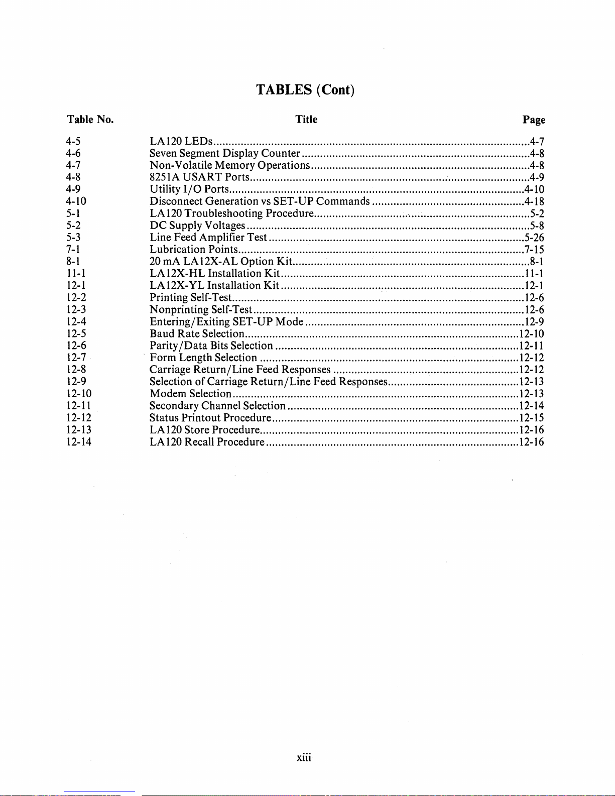
TABLES (Coot)
Table No. Title Page
4-5
LAI20LEDs
........................................................................................................
4-7
4-6 Seven Segment Display Counter...........................................................................
4-8
4-7 Non-Volatile Memory Operations........................................................................4-8
4-8 8251A
USART
Ports............................................................................................4-9
4-9 Utility
I/O
Ports.................................................................................................4-10
4-10 Disconnect Generation
vs
SET-UP Commands ..................................................4-18
5-1
LA
120
Troubleshooting Procedure.......................................................................
5-2
5-2
DC
Supply Voltages.............................................................................................
5-8
5-3
Line Feed Amplifier Test....................................................................................5-26
7-1
Lubrication Points..............................................................................................
7-15
8-1
20 rnA
LAI2X-AL
Option
Kit
..............................................................................
8-1
11-1
LAI2X-HL
Installation
Kit
................................................................................
ll-l
12-1
LAI2X-YL
Installation
Kit
................................................................................
12-1
12-
2 Printing Self-Test................................................................................................
12-6
12-3
Nonprinting Self-Test.........................................................................................
12-6
12-4 Entering/Exiting SET-UP
Mode
........................................................................
12-9
12-5
Baud
Rate
Selection..........................................................................................
12-10
12-6
Parity/Data
Bits Selection ................................................................................
12-11
12-7
.
Form
Length Selection .....................................................................................
12-12
12-8
Carriage
Return/Line
Feed Responses .............................................................12-12
12-9
Selection
of
Carriage
Return/Line
Feed Responses...........................................12-13
12-10 Modem Selection..............................................................................................
12-13
12-11
Secondary Channel Selection ............................................................................12-14
12-12 Status Printout Procedure.................................................................................
12-1
5
12-13 LA120 Store Procedure.....................................................................................
12-16
12-14 LA120 Recall Procedure...................................................................................
12-
16
xiii

MA-2313A
LA120 DECwriter
III
xiv

1.1
INTRODUCTION
CHAPTER 1
OPERATORS INFORMATION
The
LAl20
DECwriter III terminal is basically a typewriter, with a wide range
of
features,
that
com-
municates with a computer.
The
LAl20
is
easily integrated into most systems.
It
is
compatible with both EIA
and ANSI
standards.
Besides the many standard features built into the basic LA
120
DECwriter III, there are a number
of
options and accessories
that
may be added to the terminal to make it useful in an even wider range
of
applications.
Operator information contained in Chapter 1
is
for the general user
or
user already familiar with the
features
of
a terminal.
It
contains the following information:
• Description
of
operator's console
• Description
of
alarm indicators
• Operator Testing
and
troubleshooting.
Operator information
is
summarized on the
LAl20
Operator Reference
Card
(Appendix A). Table
1-1
is
a list
of
related LA
120
documents.
Tablel-l
Related Documentation
Title
LAl20
User Guide
LA
120
Pocket Service Guide
LAl20
DECwriter III
Illustrated Parts Breakdown
*Available
on
hard copy only.
**
Available
on
hard
copy
and
microfiche.
For
information
on
microfiche libraries, contact:
Digital Equipment
Corporation
Micropublishing
Group
12
Crosby Drive
Bedford,
MA
01730
Hardcopy documents can be ordered from:
Digital Equipment
Corporation
444 Whitney Street
Northboro,
MA
01532
Document Number
EK-LAI20-UG*
EK-LAI20-SV*
EK-LA
120-IP**
Attention: Communication Services
(NR2jM
15)
Customer Services Section
1-1

1.2 OPERATOR'S CONSOLE (Figure 1-1)
The
LA120 operator's console contains an office typewriter-style keyboard. The keyboard contains a
four-digit numeric display and seven indicators. There
is
provision for an optional, field installable
numeric keypad.
To
better understand the LA120 keyboard, think
of
the LA120 as two things. First, it
is
an input device
to
a computer; that is, pressing a key sends information (a code) to a computer. Second, it
is
a printer;
information is sent from the computer to the printing portion
of
the LA120. However, you can set up
your system to send information from the keyboard to the printer and computer
at
the same time.
Figure
1-2
illustrates a basic system using an LA120.
1.2.1 Lights
The console indicator lights are listed in Table
1-2.
Indicator Light
ON
tJNE
LOCAL
ALT
CHAR
SET
CTS
DSR
SET-UP
PAPER
OUT
NUMERIC
DISPLAY
Table 1-2 LA120 Console Indicators
Meaning
The LA120
is
on-line.
Data
is
transmitted and received only while on-line.
The LA120
is
in local mode. In local, LA120 operates as a typewriter and
does not transmit or receive data.
An optional alternate character set such as APL
is
in use.
Transmission
of
data
is
enabled (clear to send).
The modem
is
in data mode (data set ready).
Flashes to indicate that LA120
is
in SET-UP mode.
Flashes to indicate that printer
is
not ready due to any
of
the following
conditions.
• Paper out
• Cover open
• Print head jam
The numeric display indicates the next column number during normal
operation. In SET-UP mode the numeric display may also indicate line
number, baud rate, form length, etc.
1-2

-
I
W
SHIFT
NUMERIC
DISPLAY
/
ALTCHAR
c=J
ON
LINE LOCAL SET
o 0 0 0
TAB
CLEAR TOP R BOT
SET CLEAR
ALL
TOF LEFT
MA
RT
CTS DSR SETUP PAPER
OUT
o
O·
0 0
MAR
STORE
CLEAR
STATUS
RECALL
BAUD
Figure
1-1
Operator's Console
CODE TO
BE
PRINTED
COMPUTER
CODE
(GENERATED
WHEN A
KEY
IS PRESSED)
MA-2306
Figure
1-2
Basic System Using LA120
456
1 2 3

1.2.2 Local Control Keys
The console local
control
keys
and
their functions are listed in Table 1-3.
Table 1-3 LA120 Console Local Control Keys
Key
Function
LINE/LOCAL
Switches the LA
120
from line to local
and
vice versa as indicated by
ON
LINE
and
LOCAL
lights.
HERE
IS Transmits answerback message. This key
is
not
active in
SET-UP
mode.
LOCAL
FORM
FEED
Performs a form feed without transmitting a code to the host computer.
LOCAL
LINE
FEED
Advances
paper
one line
at
a time without transmitting a code to host
computer.
1.2.3
SET-UP
Keys
When in
SET-UP
mode, most keys
on
the console keyboard perform a
SET-UP
command
function.
SET-UP
command
functions for the
top
row
of
keys are discussed briefly in Table 1-4.
Key
SET-UP
1
"
6
@
2
#£
3
$
4
&
7
Label
SET
TAB
BOT/RT
MAR
CLEAR
TAB
CLEAR
ALL
TOF
MAR
CLEAR
Tabie 1-4 LA120 Console Set-Up Keys
Function
Places LA120 in
SET-UP
mode where LA120 features can be
examined
or
changed. In
SET-UP
mode, the numeric display
indicates line number,
baud
rate,
or
form length, etc.
Sets a horizontal
tab
stop
at
the current column. When used
with
SHIFT,
sets a vertical tab
stop
at
current
line.
Sets right margin
at
current column. When used with
SHIFT,
sets
bottom
margin
at
current line.
Clears horizontal
tab
stop
at
current column. When used with
SHIFT,
clears vertical tab stop
at
current line.
Clears all horizontal and vertical
tab
stops.
Shifted
or
unshifted designates current
paper
position as top
of
form.
If
top
of
form
is
not the same as the
top
margin,
paper
will move
to
the
top
margin (first printable line).
Clears left
and
right margins. When used with
SHIFT,
clears
top
and
bottom
margins. Left
or
top
margin becomes
J.
Right
or
bottom
margin becomes maximum allowable in the current
characters per inch (pitch) or.form length.
1-4

Key
*
8
(
9
%
5
)
o
Table 1-4 LA120 Console Set-Up Keys (Cont)
Label
STATUS
STORE/RECALL
TOP/LEFT
MAR
BAUD
Function
Prints a status message containing currently selected values
of
SET-
UP
features.
Recalls stored SET-UP parameters. When used with
SHIFT,
stores the current SET-UP parameters.
Sets left margin
at
current column. When used with
SHIFT,
sets top margin
at
current line.
Selects receive and transmit
baud
rates. When used with
SHIFT,
selects split transmit baud rates.
1.2.4 Control Character Keys
The
console control character keys
and
their functions are listed in Table
1-5.
Key
ESC
TAB
SPACE BAR
BACK
SPACE
DELETE
RETURN
LINE
FEED
CTRL
BELL
G
VT
K
FF
L
Table 1-5 LA120 Console Control Character Keys
Function
Generates code for escape (Chapter 3).
Generates code for horizontal tab.
Generates code for space.
Generates code for backspace.
Generates code for delete.
Generates code for carriage return
or
the codes for a carriage return and line feed
sequence (in
auto
line feed mode). In half duplex, the
RETURN
key can also
generate a
turnaround
character in addition to its normal code
or
codes. The turn-
around
character tells
the
computer that it
is
the computer's turn to send data.
Generates code for line feed.
When held down, modifies function or codes generated by other keys.
Hold
CTRL
down
and
press G to generate code for the bell. G
is
also used in SET-
UP
mode to change bell volume.
Hold
CTRL
down
and
press K
to
generate code for vertical tab. K
is
also used in
SET-UP mode to turn keyclick on
or
off.
Hold
CTRL
down
and
press L to generate code for form feed. L
is
also used in
SET-UP
mode
to
select
auto
line feed.
1-5
Table of contents
Other DEC Touch Terminal manuals


