Vi ringraziamo per la scelta fatta, sicuri che sarete soddisfatti del vostro acquisto.
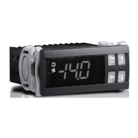
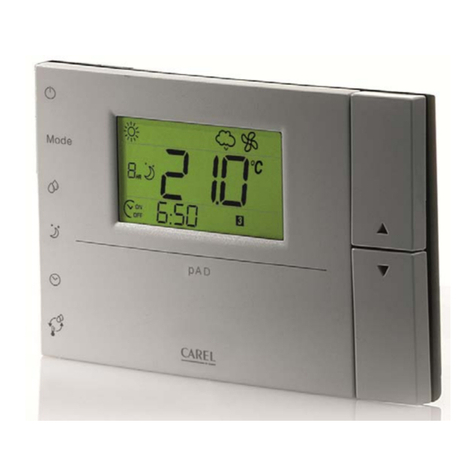
I terminali elettronici MTST sono stati progettati per essere utilizzati con i controlli MTSB Carel mettendo
a disposizione le funzioni di interfaccia operatore. Tali funzioni sono: visualizzazione numerica,
interfaccia utente con tastiera e dispositivo per programmazione con telecomando.
Inoltre, sono provvisti di: ingresso sonda di temperatura, 2 ingressi digitali e buzzer.
Installazione e collegamenti
Avvertenze generali - ambienti di destinazione e collegamenti
Le seguenti condizioni soddisfano una corretta installazione:
1. evitare il montaggio dello strumento negli ambienti che presentano: ampie e rapide fluttuazioni
della temperatura ambiente, umidità relativa maggiore dell’80%, esposizione a getti d’acqua diretti
sotto pressione, alte interferenze elettromagnetiche e/o radiofrequenze (per es. di antenne trasmittenti);
2. utilizzare capicorda adatti ai morsetti in uso. Allentare ciascuna vite ed inserirvi i capicorda, quindi
serrare le viti.
Ad operazione ultimata tirare leggermente i cavi per verificarne il corretto serraggio;
3. separare quanto più possibile i cavi delle sonde e degli ingressi digitali dai cavi dei carichi induttivi
e di potenza per evitare possibili disturbi elettromagnetici. Non inserire mai nelle stesse canaline
(comprese quelle dei cavi elettrici) cavi di potenza e cavi delle sonde. Evitare che i cavi delle
sonde siano installati nelle immediate vicinanze di dispositivi di potenza (contattori, interruttori
magnetotermici o simili);
4. ridurre il più possibile il percorso dei cavi dei sensori ed evitare che compiano percorsi a spirale
che racchiudano dispositivi di potenza. Per prolungare i cavi delle sonde, usare cavi con sezione
minima di almeno 0,5 mm2;
5. i cavi di collegamento devono garantire l’isolamento fino a 90 °C;
Sicurezza per gli operatori e precauzioni nel maneggiare la/e scheda/e.
Per tutelare la sicurezza degli operatori e la salvaguardia della scheda, prima di effettuare qualsiasi
intervento sulla scheda togliere l’alimentazione dalla stessa. I danneggiamenti elettrici che si verificano
sui componenti elettronici avvengono quasi sempre a causa delle scariche elettrostatiche indotte
dall’operatore. È quindi necessario prendere adeguati accorgimenti per queste categorie di componenti,
ed in particolare:
• prima di maneggiare qualsiasi componente elettronico o scheda, toccare una messa a terra (il
fatto stesso di evitare di toccare non è sufficiente in quanto una scarica di 10.000 V, tensione
molto facile da raggiungere con l’elettricità statica, innesca un arco di circa 1 cm);
• i materiali devono rimanere per quanto possibile all’interno delle loro confezioni originali. Se è
necessario prelevare la scheda base da una confezione trasferire il prodotto in un imballo antistatico
senza toccare il resto della scheda con le mani;
• evitare nel modo più assoluto di utilizzare sacchetti di plastica, polistirolo o spugne non antistatiche;
• evitare nel modo più assoluto il passaggio diretto tra operatori (per evitare fenomeni di induzione
elettrostatica e conseguenti scariche).
Installazione a pannello
Con riferimento alle Fig. 1 e 2 e relativi particolari:
1. praticare nel pannello un foro di dimensioni 182x153 mm;
2. svitare le due viti frontali (partt. a, b di Fig. 1) ed estrarre la portina centrale (part. c);
3. svitare le due viti (partt. d, e), che tengono uniti coperchio inferiore e frontale del terminale MTST
e quindi separare le due parti;
4. inserire sul frontale la guarnizione a pannello sovrapposta a quella interna;
5. praticare nella parte posteriore due fori (Fig. 2 partt. f, g);
6. unire la parte posteriore e il frontale, con il pannello nel mezzo, fissando il tutto con le due viti
(dimensioni 4x20* mm) contenute nel kit.
* lunghezza max 20 mm.
Avvertenza: è necessario rimuovere i due denti superiori di fissaggio (part. h) della parte frontale
prima dell’inserimento a pannello. Praticare il foro sulla parte superiore (part. i) o inferiore (part. l) del
retro per il passaggio dei cavi. Il passo delle filettature previste varia da PG9 (diametro 16 mm) a
PG21 (diametro 29 mm).
Thank you for your choice. We trust you will be satisfied with your purchase.
The electronic MTST terminals have been designed to be used with MTSB Carel’s controllers putting
at your disposal the operator interface functions. These functions are: numerical display, user
interface with keypad and a device for programming with remote control.
Moreover, they are supplied with: temperature probe input, 2 digital inputs and buzzer.
Installation and connections
General warnings – installation and connection environments
The following conditions represent the correct installation:
1. avoid installing the instrument in environments featuring: wide and rapid fluctuations in ambient
temperature, relative humidity over 80%, exposure to direct jets of pressurised water, high levels
of electromagnetic and/or radio-frequency interference (e.g. transmitting antennae);
2. use cable terminals that are suitable for the terminals being used. Loosen each screw and insert
the cable ends, then tighten the screws. Once this operation has been completed, lightly tug the
cables to check that they are sufficiently tight;
3. separate as much as possible the probe and digital input cables from cables carrying inductive
loads and power cables, to avoid any electromagnetic disturbance. Never lay power cables and
probe cables in the same channels (including those for the electrical cables). Do not install the
probe cables in the immediate vicinity of power devices (contactors, thermal overload switches or
the like);
4. reduce the path of the sensor cables as much as possible and avoid laying spiral paths around
power devices. To extend the probe cables, use cables with a minimum cross-section of at least
0.5 mm2;
5. connection cables should be suitable for 90°C operation;
Advertency. Safety information.
Before any servicing on the card disconnect power supply from the card in order to safeguard the
personnel against injury and the card itself against damages.
Electrical damage on electronic components usually occurs because of electrostatic discharges
caused by the operator.
Therefore, when handling these components, you must refer to the following:
• before using any electronic component or card, touch a grounding (it is not sufficient not to touch,
because a 10 000V discharge, a very easy voltage value to reach with static electricity, produces
an electric arc of about 1cm);
• the components must be kept inside their original package as long as possible. If necessary, take
the main board from a package and put it into an antistatic package without touching the back of
the board with your hands;
• absolutely avoid non-antistatic plastic bags or sponge and polystyrene;
• do not hand in the card directly to other among operators (to avoid any electrostatic induction and
discharges).
Panel installation
In reference to Fig. 1 and 2 and the corresponding parts:
1. Make a hole in the panel with the following dimensions: 182x153mm.
2. Unscrew the two frontal screws (Fig. 1, a, b) and take out the central door (part c).
3. Unscrew the two screws (parts d, e) that keep the lower and frontal cover of the MTST terminal
connected and separate the two parts.
4. Insert the panel gasket in the front panel, on top of the internal gasket.
5. Make two holes in the back part (Fig. 2 in the perforated part - parts f, g).
6. Join the back part and the front, with the panel in between, and fix the whole unit with the two
screws (dimensions: 4x20*mm) that are contained in the kit.
* max length 20 mm.
Warning: the two upper fastening teeth (part h) must be removed from the front panel before inserting
the unit in the panel. Make the hole on the upper (part i) or lower part (part l) of the rear for the
passage of the cables. The step of the thread can vary from PG9 (diameter 16 mm) to PG21
(diameter 29 mm).
cod. +050004110 - rel.1.0 del 09.10.01
Terminale MTST/MTST terminal
