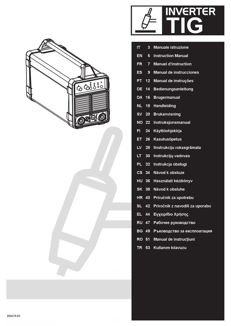
DECA WELD TIG LIFT User manual

1
950652-03 18/07/16
TIGLIFT
IT 4 Manuale istruzione
EN 7 Instruction Manual
FR 9 Manuel d’instruction
ES 12 Manual de instrucciones
PT 15 Manual de instruções
DE 18 Bedienungsanleitung
DA 21 Brugermanual
NL 23 Handleiding
SV 26 Brukanvisning
NO 29 Instruksjonsmanual
FI 32 Käyttöohjekirja
ET 34 Kasutusõpetus
CS 45 Návod k obsluze
HU 48 Használati kézikönyv
SK 50 Návod k obsluhe
HR
AR 73

1
950652-03 18/07/16

2
950652-03 18/07/16
•
(IT)(EN)(FR)(ES) SEÑALES
(PT)(EL)(DE)
(DA) (NL) (SV)
(FI)(ET)(LV)
(LT) (PL)
(CS) (SK)
(HU) (RU) (BG)
(HR)(NO)(SL)
IN PREPOVEDI (RO)(TR))

3
950652-03 18/07/16
•
(IT)
(EN)
(FR)
(ES)
(PT)
(DE)
(DA)
(NL)
(SV)
(NO)
(FI)
(ET)
(LV)
(LT)

4
950652-03 18/07/16
IT
Manuale istruzione
IEC o CLC/TS 62081
Avvertenze di sicurezza
Fig 8 DaDb
Apparecchiatura di Classe A
IEC o CLC/TS 62081
IEC o CLC/TS 62081
(PL)
(CS)
(HU)
(SK)
(HR)
(SL)
(EL)
(RU)
(BG)
(RO)
(TR)

5
950652-03 18/07/16
Messa in funzione
Assemblaggio ed allacciamento elettrico
¾(Fig.5) ** .
¾
Fig.3,1
L
L
Fig.3,4
¾
(2P+ T per 1Ph) (3P+ T per 3Ph) di portata
Fig3,2
Allacciamento a motogeneratori
Preparazione del circuito di saldatura MMA
¾
¾
L
Preparazione del circuito di saldatura TIG
¾
(Mod. 1, 2)
¾
¾
(Mod.3)
¾
¾“Z”
¾Y
Fig.7
L
Fig.3,3
** (Questo componente può non essere incluso su alcuni modelli).
Descrizione della saldatrice
Fig.1.
Organi principali Fig.1
Mod.1
Mod.2
Mod.3
Stand By
Dati tecnici
Fig.2
D1D2 Saldatura
1˜
F1F2
U0V
I2, U2
X
A / V
U1
I1 eff
I1 max
Fig.6
** (Questo componente può non essere incluso su alcuni modelli).
Procedimento di saldatura: descrizione comandi e
segnalazioni
Mod.1
Selettore MMA / TIG “D”
“D”
MMA:
TIG
Regolazione corrente di saldatura “E”
nella Fig.4
L
L
Regolazione “Arc Force”
L
L“D”
¾Arc Force“D1”“AF”
¾Ruota il potenziometro “E”
¾“D”
“A”

950652-03 18/07/16
Spia tensione d’alimentazione e di segnalazione
anomalia “G”
Hi =
Lo =
L“D”
Spia di segnalazione intervento termico “F”
“t”
“X” protettore
termico
Mod.3
¾“D”.
¾ “H”
la manopola “E”
Pulsante Stand By / ON “C”
Premilo per accendere la macchina o per metterla in “Stand By
Stand By
“G”
Selettore MMA / CELLULOSIC / TIG “D”
“D”
MMA:
CELLULOSIC
TIG LIFT
L
L
Saldatura MMA: parametri regolabili “H”
¾“I (Amp)”
¾“ARC FORCE
¾“HOT START”
Antisticking
Saldatura Tig: parametri regolabili “H”
¾“SLOPE-UP”
“I (Amp)”.
L
¾“I (Amp)”
¾“SLOPE-DOWN”
L
¾“POST-GAS”POST-GAS“Aut”
Spia di segnalazione comando remoto (pedale) collegato
“J”
Spia di segnalazione intervento termico “F”
Xprotettore termico
Regolazione “Hot Start”
L
¾“D”
¾Hot Start“D2”“HS”
¾Ruota il potenziometro “E”
¾“D”
“A”
Antisticking
“AS”
Spia tensione d’alimentazione e di segnalazione
anomalia “G”
Hi =
Lo =
L“D”
Spia di segnalazione intervento termico “F”
F”
“t”
“X” protettore
termico
Mod.2
Pulsante Stand By / ON “C”
Premilo per accendere la macchina o per metterla in “Stand By
Stand By
“G”
Selettore MMA / TIG “D”
“D”
MMA:
TIG
Regolazione corrente di saldatura “E”
nella Fig.4
L
L
Regolazione “Arc Force”
L
¾“D”
¾Arc Force“AF”
¾“E”
¾“D”
Regolazione “Hot Start”
L
¾“D”
¾Hot Start“HS”
¾“E”
¾“D”
Antisticking
“AS”
Regolazione “Slope Down”
L
¾“D”
¾“Slope Down“SD”
¾“E”
¾“D”

950652-03 18/07/16
Fig. 8 DaDb
Class A equipment
IEC or CLC/TS 62081
IEC or CLC/TS 62081
Starting up
Assembly and electrical connections
¾(Fig.5) **.
¾
3,1
L
L
Fig.3,4.
¾
3,2
Connection to motor generators
Preparing the welding circuit MMA
¾
¾
L
Consigli per l’uso
LAl primo
Manutenzione
Manutenzione straordinaria
elettromeccanico periodicamente
EN
Instruction Manual
: IEC or CLC/TS 62081.
Safety warnings

8
950652-03 18/07/16
U1
I1 eff
I1 max
Fig.6
** (This component may not be included with some models).
Welding process: description of controls and signals
Mod.1
MMA / TIG Selector “D”
Adjusting the welding current “E”
Fig. 4
L
L
“Arc Force” Adjustment
L
¾“D”
¾Select the “Arc Force”“D1”“AF”
¾“E”
¾“D”
“A”
“Hot Start” Adjustment
L
¾“D”
¾Select the “HOT START“D2”“HS”
¾“E”
¾“D”
“Anti-sticking”
Supply voltage and failure indicator “G”
Hi =
Lo
L“D”
Thermal cutout signal “F”
“F”
“t”
“X”thermal cutout
Mod.2
Stand By / ON button “C”
Stand By
Stand By
“G”
MMA / TIG Selector “D”
“D”
Adjusting the welding current “E”
Preparing the welding circuit TIG
¾
(Mod. 1, 2)
¾
¾
(Mod.3)
¾
¾“Z”
¾Y
Fig. 7
L
Fig. 3,3
** (This component may not be included with some models).
Description of the welding machine
Fig. 1.
Main parts Fig. 1
Mod.1
Mod.2
Mod.3
Technical data
Fig. 2
D1D2:
1˜
3˜
F1: F2:
U0V
I2, U2
X
A/V

950652-03 18/07/16
Fig. 4
L
L
“Arc Force” Adjustment
L
¾“D”
¾Select the “ARC FORCE“AF”
¾ “E”
¾“D”
“Anti-sticking”
“AS”
“Slope Down” Adjustment
“Slope Down”
L
¾“D”
¾Select the “SLOPE DOWN“SD”
¾“E”
¾“D”
Supply voltage and failure indicator “G”
Mains voltage pilot lamp
Hi =
Lo
L“D”
Thermal cutout signal “F”
“t”
“X”thermal cutout
Mod.3
¾“D”
¾“H”
“E”
Stand By / ON button “C”
Stand By
Stand By
“G”
MMA / CELLULOSIC / TIG selector “D”
“D”
L
L
MMA welding: adjustable parameters “H”
¾“I (Amp)
¾“ARC FORCE(led slope up)
¾“HOT START” (led I%)
“Anti-sticking”
Tig welding: adjustable parameters “H”
¾“SLOPE-UP”
I (Amp)
¾“I (Amp)
¾“SLOPE-DOWN
¾“POST-GASPOST-GAS In the “Aut”
Remote (Foot pedal) control connection pilot lamp “J”
Thermal cutout signal “F”
Xthermal cutout
Recommendations for use
L
Maintenance
Extraordinary maintenance
FR
Manuel d’instruction
,
IEC ou CLC/TS 62081.
Avertissements de sécurité

950652-03 18/07/16
Fig 8 DaDb
Appareillage de Classe A
IEC ou CLC/TS 62081
IEC ou
CLC/TS 62081
Mise en service
Montage et raccordement électrique
¾ (Fig. 5) ** .
¾
Fig3,1
L
L
Fig.3,4
¾
Fig3,2
Raccordement aux moto-générateurs
Préparation du circuit de soudage MMA
¾
¾
L
Préparation du circuit de soudage TIG
¾
(Mod. 1, 2)
¾
¾
(Mod.3)
¾
¾«Z»
¾« Y»
Fig.7
L
Fig.3,3
** (Ce composant peut ne pas être inclus pour certains modèles).
Description de la soudeuse
Fig. 1.
Principaux organes Fig.1
Mod.1
Mod.2

11
950652-03 18/07/16
Réglage de l’”Arc Force”
L
¾“D”
¾“Arc Force”“D1”“AF”
¾“E”
¾“D”
“A”
Réglage du “Hot Start”
¾“D”
¾“Hot Start”“D2”“HS”
¾“E”
¾“D”
“A”
Anti-collage
“AS”
Témoin de tension d’alimentation et de signalisation
d’anomalie “G”
“G”
“G”
Hi =
Lo
L“d”
Témoin de signalisation de l’intervention thermique
«F»
“t”
“X”
un protecteur thermique
Mod.2
Bouton Stand By / ON “C”
Stand
ByStand By
«G»
Sélecteur MMA / TIG “D”
“D”
Réglage du courant de soudage «E»
Fig.4
L
L
Réglage de l’ ”Arc Force”
L
¾“D”
¾“Arc Force”“AF”
¾“E”
¾“D”
Réglage du “Hot Start”
L
¾“D”
¾“Hot Start”“HS”
¾“E”
¾“D”
Anti-collage
“AS”
Mod.3
Caractéristiques techniques
Fig.2
D1:D2:
1˜
3˜
F1F2:
U0V
I2, U2
X
A / V
U1
I1 eff
I1 max
Fig.6
** (Ce composant peut ne pas être inclus pour certains modèles).
Procédé de soudage: description des commandes et
signalisations
Mod.1
Sélecteur MMA / TIG “D”
“D”
Réglage du courant de soudage «E»
Fig.4
L
L

12
950652-03 18/07/16
Réglage du “Slope Down”
“Slope Down”
L
¾“D”
¾“Slope Down” SD”
¾“E”
¾“D”
Témoin de tension d’alimentation et de signalisation
d’anomalie “G”
Sur le
Hi =
Lo
L“D”
L
Témoin de signalisation de l’intervention thermique «F»
“F”
“t”
“X”
un protecteur thermique
Mod.3
¾ “D”
¾“H”
“E”
Bouton Stand By / ON “C”
Stand
ByStand By
“G”
Sélecteur MMA / CELLULOSIC / TIG «D»
TIG LIFT
L
L
Soudage MMA : paramètres réglables “H”
¾“I (Amp)”
¾“ARC FORCE” (led slope up)
¾“HOT START” (led I%)
Anti-collage
Soudage Tig : paramètres réglables “H”
¾“SLOPE-UP
I (Amp)
L
¾“I (Amp)
¾“SLOPE-DOWN”
L
¾“POST-GAS“Aut”
Témoin de signalisation commande à distance (pédale)
connecté "J"
Témoin de signalisation de l’intervention thermique «F»
X
protecteur thermique
Conseils d’utilisation
L
Entretien
Entretien extraordinaire ,
ES
Manual de instrucciones
,
IEC o CLC/TS 62081
Advertencias de seguridad

13
950652-03 18/07/16
Fig 8 Da = cm
Db
Equipo de Clase A
riesgo, con el peligro adicional de
,
IEC o CLC/TS 62081
IEC o CLC/TS 62081
Puesta en funcionamiento
Ensamblaje y conexión eléctrica
¾(Fig. 5) ** .
¾
Fig.3,1
L
L
Fig.3,4.
¾
la capacidad adecuada Fig.3,2
Conexión a motogeneradores
Preparación del circuito de soldadura MMA
¾
¾
L
Preparación del circuito de soldadura TIG
¾
(Mod. 1, 2)
¾
(Mod.3)
¾
¾“Z”
¾“Y”
Fig.7.
L
Fig.3,3.
** (Este componente puede no estar incluido en algunos modelos).
Descripción de la soldadora
Fig. 1.
Piezas principales Fig.1
Mod.1
Mod.2
E
Mod.3
Interruptor principal

14
950652-03 18/07/16
Datos técnicos
Fig.2
D1D2
F1F2
U0V
I2, U2
X
A / V
U1
I1 eff
I1 max
Fig.6
** (Este componente puede no estar incluido en algunos modelos).
Procedimiento de soldadura: descripción mandos y
señalaciones
Mod.1
Selector MMA / TIG “D”
“D”
Regulación de corriente de soldadura “E”
indican en la Fig.4
L
L
Regulación “Arc Force”
L
¾“D”
¾Seleccionar el modo “Arc Force”“D1”“AF”
¾Girar el potenciómetro “E”
¾“D”
“A”
Regulación “Hot Start”
L
¾“D”
¾Seleccionar el modo “Hot Start”“D2”“HS”
¾Girar el potenciómetro “E”
¾“D”
“A”
Antisticking
“AS”
Testigo de tensión de alimentación y de señalización
de anomalía “G”
“G”
“G”
Hi =
Lo
L“D”
Dispositivo luminoso que indica un accionamiento
térmico “F”
“F”
“t”
“X”
un protector térmico
Mod.2
Botón Stand By/ON “C”
Stand By
Stand By
“G”
Selector MMA / TIG “D”
“D”
Regulación de corriente de soldadura “E”
indican en la Fig.4
L
L
Regulación “Arc Force”
L
¾“D”
¾Seleccionar el modo “Arc Force”“AF”
¾“E”
¾“D”
Regulación “Hot Start”
L
¾“D”
¾Seleccionar el modo “Hot Start”“HS”
¾“E”
¾“D”
Antisticking
“AS”
Regulación “Slope Down”
L
¾“D”
¾Seleccionar el modo “Slope Down” SD”
¾“E”
¾“D”
Testigo de tensión de alimentación y de señalización
de anomalía “G”
Hi =
Lo
L“D”

15
950652-03 18/07/16
Dispositivo luminoso que indica un accionamiento
térmico “F”
“F”
“t”
“X”
un protector térmico
Mod.3
¾“D”
¾“H”
“E”
L
indican en la Tabla 1
Botón Stand By/ON “C”
Stand By
Stand By
“G”
Selector MMA / CELLULOSIC / TIG “D”
Soldadura MMA: parámetros ajustables “H”
“I (Amp)”
¾“ARC FORCE”
¾“HOT START”
Soldadura TIG: parámetros ajustables “H”
¾“SLOPE-UP”
I (Amp)
L
¾“I (Amp)”
¾“SLOPE-DOWN”
L
¾“POST-GAS”“Aut”
Dispositivo luminoso que indica la conexión del
mando a distancia (pedal) “J”
Dispositivo luminoso que indica un accionamiento
térmico “F”
X
un protector térmico
Recomendaciones para el uso
LLa
Mantenimiento
Mantenimiento extraordinario
, en
PT
Manual de instruções
em
ncia
: IEC ou CLC/TS 62081.
Advertências de segurança

950652-03 18/07/16
Fig. 8 Da =
Db
Aparelhagem de Classe A
IEC ou CLC/TS 62081
IEC ou CLC/TS 62081
Pôr a funcionar
Montagem e ligação eléctrica
¾(Fig.5) ** .
¾
Fig.3,1
L
L
Fig.3,4.
¾
Fig.3,2
Ligação em motogeradores
Preparação do circuito de soldadura MMA
¾
¾
L
Preparação do circuito de soldadura TIG
¾
(Mod. 1, 2)
¾
¾
(Mod. 3)
¾
¾
¾“Z”
¾“Y”
Fig.7
L
Fig.3,3.
** (Este componente pode não estar incluído em alguns modelos).
Descrição da soldadora
Fig. 1.
Órgãos principais Fig.1
Mod.1
Mod.2
Mod.3
Dados técnicos
Fig.2
D1D2
1˜
3˜
F1F2
3˜
U0V
I2, U2

950652-03 18/07/16
X
A / V
U1
I1 eff
I1 máx
Fig.6
** (Este componente pode não estar incluído em alguns modelos).
Procedimento de soldadura: descrição comandos e
sinalizações
Mod.1
Seletor MMA / TIG “D”
“D”
Regulação da corrente de soldadura “E”
Fig.4
L
L
Regulagem “Arc Force”
L
¾“D”
¾Seleccione a modalidade “Arc Force”“D1”“AF”
¾“E”
¾“D”
“A”
Regulagem “Hot Start”
L
¾“D”
¾Selecione a modalidade “Hot Start”“D2”“HS”
¾“E”
¾“D”
“A”
Antisticking
“AS”
Sinalizador tensão de alimentação e de indicação
anomalia “G”
Sinalizador “G”
Sinalizador “G”
Hi =
Lo =
L“D”
Luz piloto de sinalização da intervenção térmica “F”
A luz piloto “F”
“t”
“X”protector térmico
Mod.2
Botão Stand By / ON “C”
Stand By
Stand By
G”
Seletor MMA / TIG “D”
“D”
Regulação da corrente de soldadura “E”
Fig.4
L
L
Regulagem “Arc Force”
L
¾“D”
¾Seleccione a modalidade “Arc Force”“AF”
¾“E”
¾“D”
Regulagem “Hot Start”
L
¾“D”
¾Selecione a modalidade “Hot Start”“HS”
¾“E”
¾“D”
Antisticking
“AS”
Regulagem “Slope Down”
L
¾“D”
¾Seleccione a modalidade “Slope Down” “SD”
¾“E”
¾“D”
Sinalizador tensão de alimentação e de indicação
anomalia “G”
Led intermitente
Hi =
Lo =
L“D”
Luz piloto de sinalização da intervenção térmica “F”
A luz piloto “F”
“t”
“X”protector térmico
Mod.3
¾“D”
¾“H”
“E”
L
Tab.1
Botão Stand By / ON “C”
Stand By
Stand By
“G”
Selector MMA / CELLULOSIC / TIG “D”

18
950652-03 18/07/16
Fig 8 DaDb
Gerät der Klasse A
IEC oder CLC/TS 62081
Soldadura MMA: parâmetros reguláveis “H”
¾“I (Amp)”
¾“ARC FORCE”
¾“HOT START” (
Soldadura Tig: parâmetros reguláveis “H”
¾“SLOPE-UP”
I (Amp)
L
¾“I (Amp)”:
¾“SLOPE-DOWN”
L
¾“POST-GAS” “Aut”
Indicador luminoso de sinalização comando remoto (pedal)
ligado “J”
Luz piloto de sinalização da intervenção térmica “F”
Xprotector térmico
Conselhos para o uso
LNa primeira
utilizaçã
Manutenção
Manutenção extraordinária
DE
Bedienungsanleitung
: IEC oder CLC/TS 62081 .
Sicherheitshinweise

950652-03 18/07/16
IEC oder CLC/
TS 62081
Inbetriebnahme
Zusammenbau und Stromanschluss
(Abb. 5) ** .
¾
Abb3,1
L
L
Abb.3,4
¾
Abb.3,2
Anschluss an Motorgeneratoren
Vorbereitung des Schweißkreises MMA
¾
¾
L
Vorbereitung des Schweißkreises TIG
¾
(Mod. 1, 2)
¾
¾
¾
(Mod. 3)
¾
¾ “Z
¾“Y”
Abb.7
L
Abb.3,3
** (Dieses Teil kann bei einigen Modellen fehlen).
Beschreibung der Schweißmaschine
Abb.1
Hauptbauteile Abb.1
Mod.1
Mod.2
Mod.3
Technische Daten
Abb. 2
D1D2
1˜
F1F2
U0V
I2,U2
X
A / V
U1
I1 eff
I1 max
Abb.6
** (Dieses Teil kann bei einigen Modellen fehlen).
Schweißverfahren: Beschreibung der
Bedienvorrichtungen und Anzeigen
Mod.1
Wählschalter MMA / TIG “D”
“D”
This manual suits for next models
1
Table of contents
Languages:
Other DECA WELD Inverter manuals
Popular Inverter manuals by other brands
Audiovox
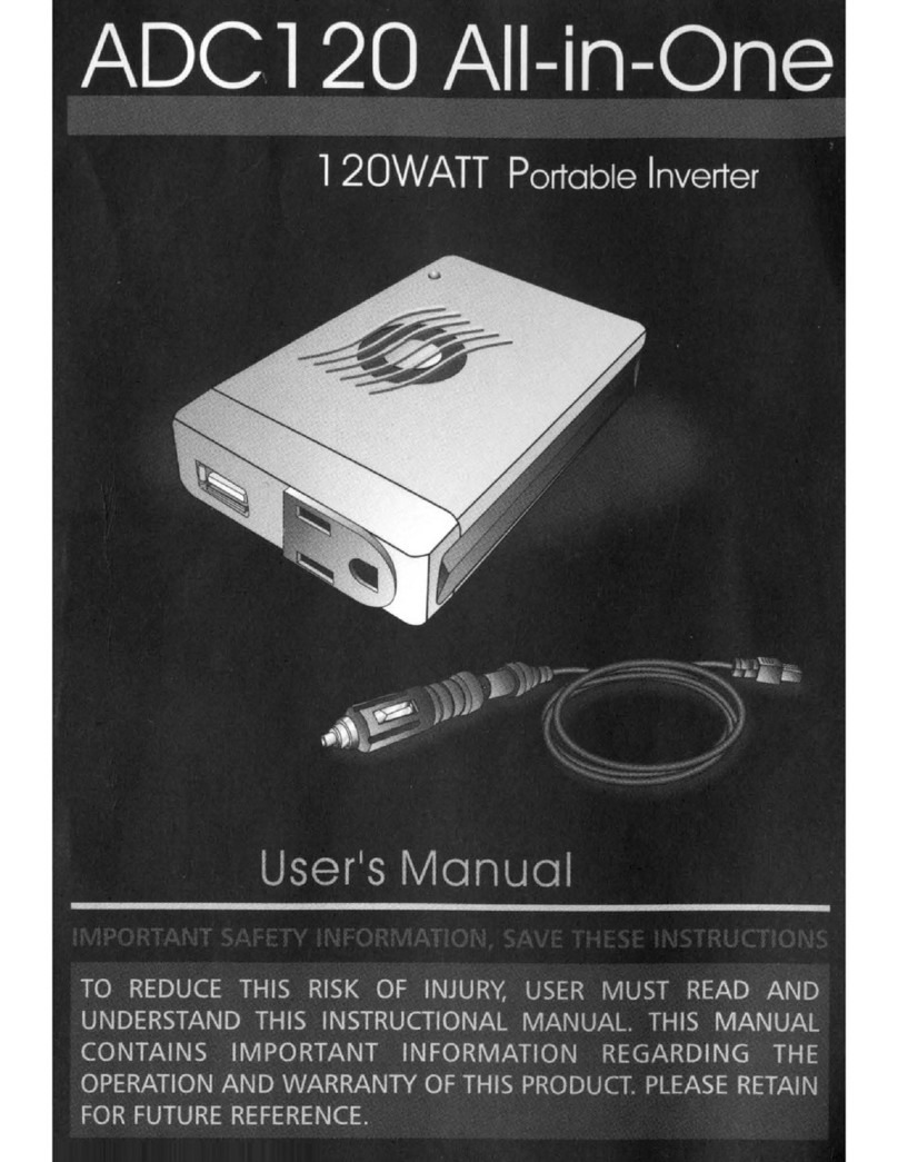
Audiovox ADC120 - DC to AC Power Inverter user manual
SolarCity
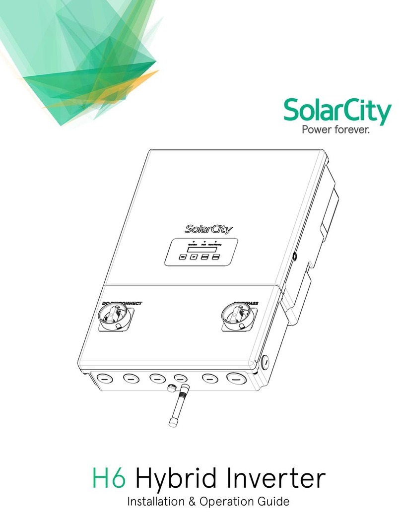
SolarCity H6 Installation & operation guide

Sunforce
Sunforce Pro Series user manual

Samil Power
Samil Power SolarLake 12000TL-PM installation guide

Fusion
Fusion 25512 Use and care guide
CHNT Power
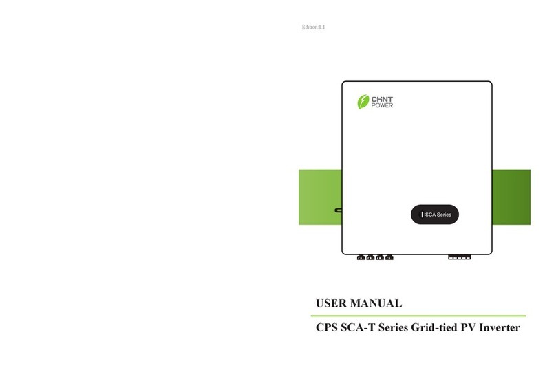
CHNT Power CPS SCA-T Series user manual
