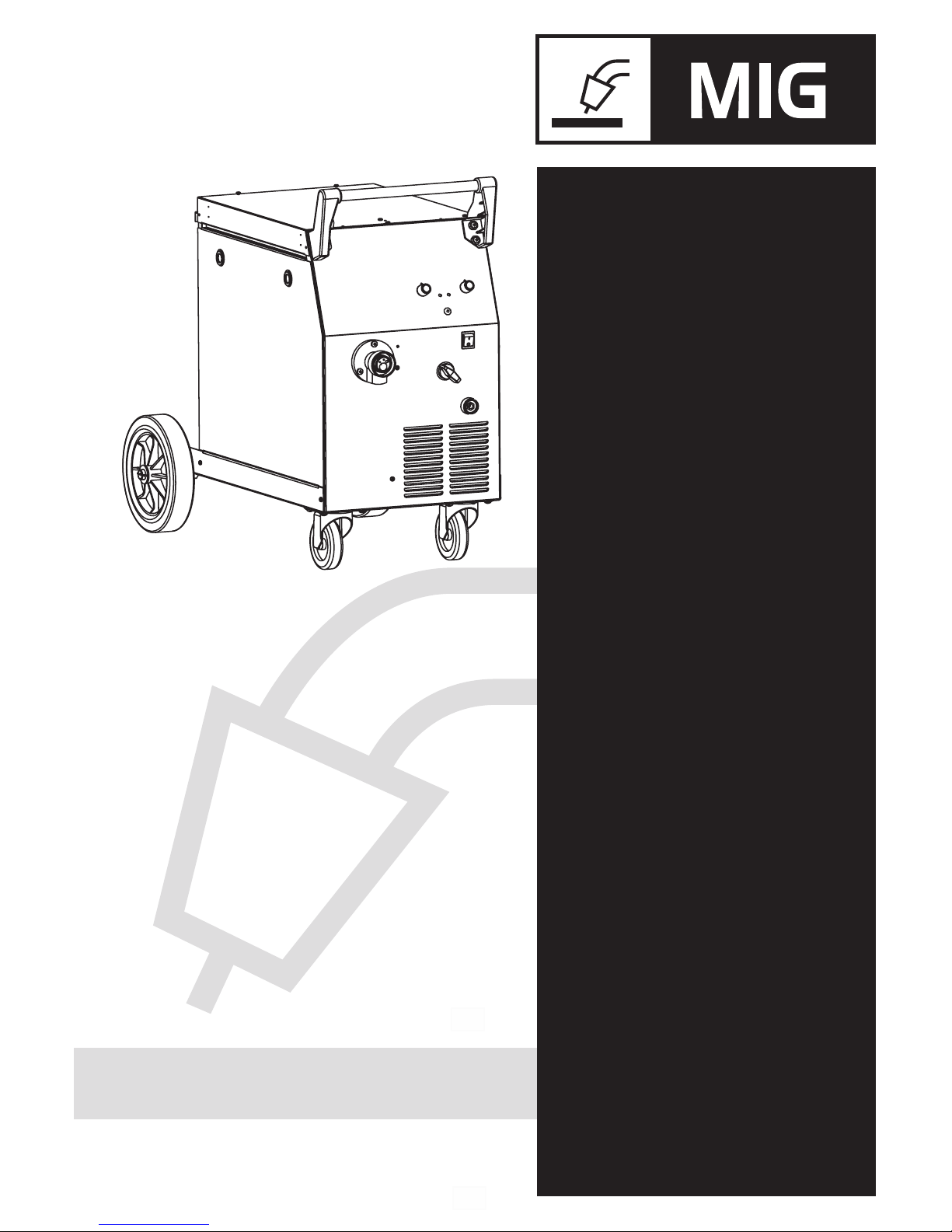
Deca D-MIG500 User manual
1
950568-03 22/08/16
IT 4 Manuale istruzione
EN 6 Instruction Manual
FR 7 Manuel d’instruction
ES 9 Manual de instrucciones
PT 11 Manual de instruções
DE 13 Bedienungsanleitung
DA 15 Brugermanual
NL 17 Handleiding
SV 19 Brukanvisning
NO 20 Instruksjonsmanual
FI 22 Käyttöohjekirja
ET 24 Kasutusõpetus
CS 31 Návod k obsluze
HU 33 Használati kézikönyv
SK 35 Návod k obsluhe
HR
AR 50

1
950568-03 22/08/16
I1max= x,xA
xx% xxx%
EN 60 974/1
U1= xxxV
Xxx%
IP 21
S
TYPE: xxxxxxxxxxxxxxx
I2xxxA xxxA xxA
U2xx x,V xx,xV xx,xV
xx A/xxV-xxx A/xxV(max xxxA/xxV)
x~xx/xxHz
I1eff= x,xA
UV
0
Xx,x-xx,x
Xxxxxxxxxxxxxx
SN: xxxxxxxxxxxxxxx
T2
T2
Fig.5
Fig.3
220 V 230 V 240 V
380 V 400 V 415 V
A
B
I
J
C
D
E
H
F
G
Fig.2
K
Kg LM
Fig.1
Fig.4
I
max
(A)
2
180
190
220
10A”C”
10A”D”
16A”C”
16A”D”
16A16A
16A32A
16
16
240V
230V
220V
16A”D”
415V
16A
mm
16
1~3~
2
Steel-Fe
IMax
(A)
2
0,8-1,0
Inox-Ss
180
-
220
0,8-1,0
Aluminium
Al
Ar/He/Co2
Ar/O2
Ar/Co2
Ar/Co2
Co2
Ar
Ø mm.
0,6-0,8-1,0
x
400V
CT
CT
M2
400V
230V
230V
M2
!
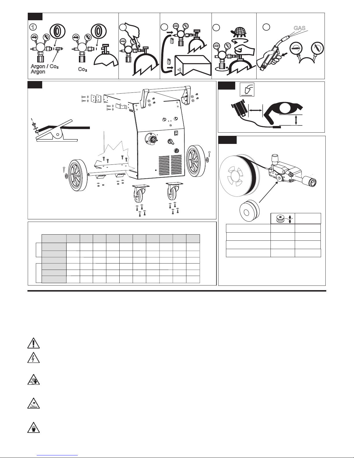
6-2 Kg 5Ø200 Kg 15 Ø 300
6-1
Fig.6
6-6
6-10
b
6-9
6-8
6-7
a
c
OK
6-3
6-4
6-5
6-11
6-12
5-10 cm
OK
!
6-13 6-15
6-14
4,1 4,2 4,3
1
2
F
I
6
3
240 32A”C” 32A 16
400V
380V
240V
230V
220V
415V
400V
380V
1,5-18
1,5-18
1,5-18
1,5-18
4,4
SPEED
m/min
m/min
ML
E
D
B
C
H
A
45
2
950568-03 22/08/16
Fig.8
1
Argon/Co
Argon
2
Co2
345
GAS
6-8Lt/min
2
Fig.7
db
da
Fig.9
Fig.10
Steel-Fe0,6-0,8
0,8-1,0
Aluminium -Al
Ø mm.
Ref.
010647
Steel-Fe1,0-1,2 010628
Flux 0,9 010627
010629
1
30
25
20
20
20
2
50
50
34
40
28
3
70
80
48
65
35
4
90
110
63
85
45
56
150
170
90
8
115
Conventional output current EN /IEC 60974-1:2012
1~
I max (A)
2
3~
180A
240A
190A
220A
220A
9
140
10
160
7
115
150
90
115
60
140
200
120
140
75
•
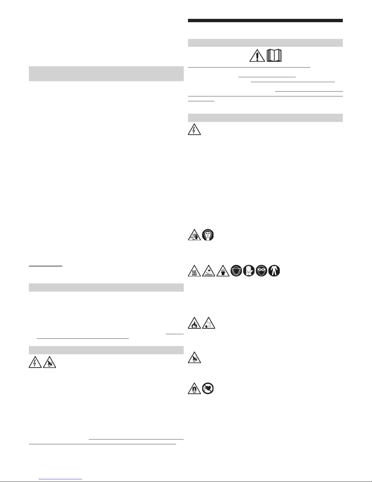
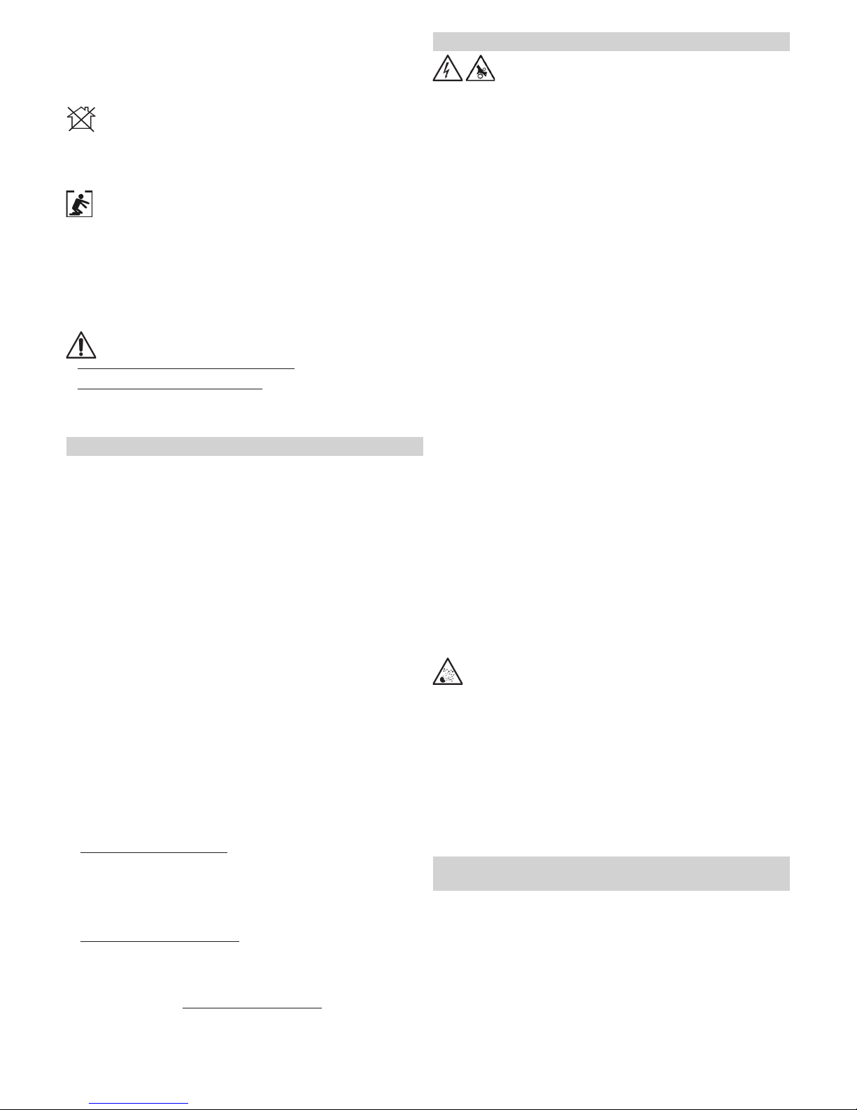
(IT)(EN)(FR)(ES) SEÑALES
(PT)(EL)(DE)
(DA)(NL)(SV)
(FI)(ET)(LV)
(LT)(PL)
(CS) (SK)
(HU)(RU) (BG)
(HR)(NO)(SL)
IN PREPOVEDI (RO)(TR))

3
950568-03 22/08/16
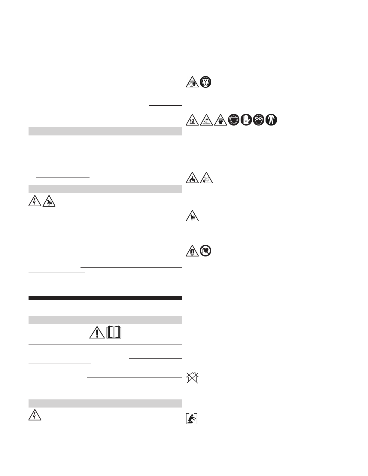
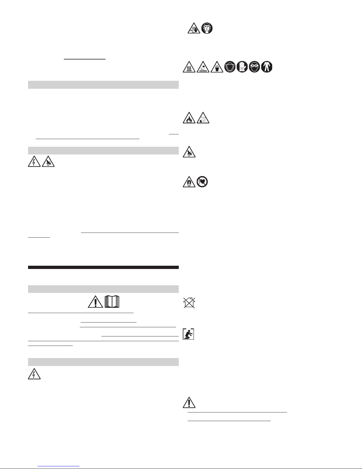
•
(IT)
(EN)
(FR) Elimination
(ES) Eliminación de
(PT) Eliminação de
(DE)
(DA)
(NL)
(SV)
(NO)
(FI)
(ET)
(LV)
(LT)
(PL)

4
950568-03 22/08/16
IT
Manuale istruzione
: IEC o CLC/TS 62081.
Avvertenze di sicurezza
Fig 9 DaDb
Apparecchiatura di Classe A
Saldatura in condizioni a rischio
scariche elettriche, soffocamento, in
Avvertenze supplementari
Descrizione della saldatrice
(CS)
(HU)
(SK)
(HR)
(SL)
(EL)
(RU)
(BG)
(RO)
(TR)

5
950568-03 22/08/16
Fig. 1.
Organi principali Fig.1
**
** (Questo componente può non essere incluso su alcuni modelli).
Dati tecnici
Fig.2
U0V
I2, U2
X
A / V
U1
I1 eff
I1 max
Fig.3
Messa in funzione
Assemblaggio ed allacciamento elettrico
¾Fig.8.
¾
Fig.4,1.
L Se
¾Spina d’alimentazione
(2P+T per 1Ph e 3P+T per 3Ph) di portata
Fig.4,2.
¾
Fig.5.
L
Preparazione del circuito di saldatura
¾
L
Fig.4,3
Fig.6
Fig.6,5,a,
Fig.6,9,b
LFig.6,5,c
L
Installazione della bombola del gas di protezione** e del
riduttore di pressione**
Fig.7
Gas Applicazione
L
L
** (Questo componente può non essere incluso su alcuni modelli).
Procedimento di saldatura: descrizione comandi e
segnalazioni
Fig.1 (#1)
1) Regolazione corrente di saldatura
L
Fig.4,4
3) Timer del tempo di saldatura
4) Burn back
5) Rampa
6) Spia di segnalazione intervento termico
X protettore
termico
Consigli per l’uso
L
Manutenzione
Manutenzione ordinaria

950568-03 22/08/16
Fig 9 DaDb
Class A equipment
Welding in conditions of risk
(electric discharges, suffocation, the
Additional warnings
Description of the welding machine
Fig. 1.
Main parts Fig. 1
** (This component may not be included on some models).
Technical data
Fig. 2
U0V
I2, U2
X
A / V
U1
I1 eff
I1 max
Fig.10
Manutenzione straordinaria
elettromeccanico periodicamente
EN
Instruction Manual
: IEC or CLC/TS 62081.
Safety warnings

950568-03 22/08/16
4) Burn back
5) Soft start
6) Thermal cutout signal
Xthermal cutout
Recommendations for use
L
Maintenance
Ordinary maintenance
Fig.10
Extraordinary maintenance
FR
Manuel d’instruction
,
IEC ou CLC/TS 62081.
Avertissements de sécurité
Fig.3
Starting up
Assembly and electrical connections
¾Fig. 8.
¾
Fig. 4,1.
L
¾Plug(2P+T for 1Ph
and 3P+T for 3Ph)Fig.4,2.
¾
Fig. 5
L
Preparing the welding circuit
¾
¾Connect the torch
L
Fig. 4,3.
Installing the continuous wire
Fig. 6
Fig.
6,5,a, the contact tip Fig. 6,9,b
LFig. 6,5,c
L
Installing the protective gas cylinder** and pressure reducer**
Fig. 7
Gas Application
2
2
CO2
L
L
** (This component may not be included with some models).
Welding process: description of controls and signals
Fig. 1
1) Adjusting the welding current
L
2) Adjusting the wire speed
Fig.4,4
3) Welding timer

950568-03 22/08/16
Description de la soudeuse
Fig. 1.
Principaux organes Fig.1
** (Ce composant peut ne pas être inclus pour certains modèles).
Caractéristiques techniques
Fig.2
1˜
3˜
U0V
I2, U2
X
A / V
U1
I1 eff
I1 max
Fig.3
Mise en service
Montage et raccordement électrique
¾Fig.8.
¾
Fig.4,1
L
¾Fiche d’alimentation
(2P + T pour 1Ph et 3P + T pour 3Ph)
Fig.4,2.
L
Fig.5
L
Préparation du circuit de soudage
¾
¾
L
Fig.4,3.
Fig.6
Fig 9 DaDb
Appareillage de Classe A
Soudage en situations de risque
(décharges électriques, suffocation,
Avertissements supplémentaires
950568-03 22/08/16
Fig.6,5,a
Fig.6,9,b
.
LFig.6,5,c
L
Installation de la bouteille de gaz de protection** et du
réducteur de pression**
Fig.7
Gaz Application
2
2
CO2
L
L
** (Ce composant peut ne pas être inclus pour certains modèles).
Procédé de soudage : description commandes et
signalisations
Fig.1
1) Réglage du courant de soudage
L
continu Fig.4,4.
3) Temporisateur du temps de soudage
5) Rampe
6) Témoin de signalisation de l’intervention thermique
X
protecteur thermique
Conseils d’utilisation
L
Entretien
Entretien ordinaire
Fig.10
Entretien extraordinaire ,
ES
Manual de instrucciones
,
IEC o CLC/TS 62081
Advertencias de seguridad
950568-03 22/08/16
Fig 9 Da
Db
Equipo de Clase A
Soldadura en condiciones de riesgo
riesgo, con el peligro adicional de
,
Advertencias adicionales
.
Descripción de la soldadora
Fig. 1.
Piezas principales Fig.1
** (Este componente puede no estar incluido en algunos modelos).
Datos técnicos
Fig.2
U0V
I2,U2
X
A / V
U1
I1 eff
I1 max
Fig.3
Puesta en funcionamiento
Ensamblaje y conexión eléctrica
¾Fig.8.
¾
Fig.4,1.
L
¾Enchufe de alimentación
(2P + T por 1Ph y 3P + T por 3Ph) con
la capacidad adecuada Fig.4,2.
¾
Fig.5.
L
Preparación del circuito de soldadura
¾
¾
L
Fig.4,3.
Instalación del hilo continuo
Fig.6
Fig.6,5,a, a la punta de contacto Fig.6,9,b
LFig.6,5,c
L
Instalación de la bombona de gas de protección** y del
reductor de presión**
Fig.7
11
950568-03 22/08/16
PT
Manual de instruções
em
: IEC ou CLC/TS 62081.
Advertências de segurança
L
L
** (Este componente puede no estar incluido en algunos modelos).
Procedimiento de soldadura: descripción mandos y
señalaciones
Fig.1.
1) Regulación de corriente de soldadura
L
2) Regulación de la velocidad del hilo
continuo Fig.4,4.
3) Temporizador de soldadura
4) Burn back
5) Inicio suave
6) Dispositivo luminoso que indica un accionamiento térmico
X
protector térmico
Recomendaciones para el uso
LLa primera
Mantenimiento
Mantenimiento ordinario
Fig.10
Mantenimiento extraordinario
, en
12
950568-03 22/08/16
Fig. 9 DaDb =
Aparelhagem de Classe A
Soldadura em condições a risco
descargas eléctricas,
sufocamento,
Advertências suplementares
Descrição da soldadora
Fig. 1.
Órgãos principais Fig.1
** (Este componente pode não estar incluído em alguns modelos).
Dados técnicos
Fig.2
1˜
3˜
U0V
I2, U2
X
A / V
U1
I1 eff
I1 máx
Fig.3
Pôr a funcionar
Montagem e ligação eléctrica
¾Fig.8.
¾
Fig.4,1.
L
¾Ficha de alimentação
(2P+T para 1Ph e 3P+T para 3Ph)
Fig.4,2.
¾
Fig.5
L
Preparação do circuito de soldadura
¾
¾
L
Fig.4,3
Fig.6
Fig.6,5,aFig.6,9,b
LFig.6,5,c
L
Instalação da botija do gás de protecção** e do redutor de
pressão**
Fig.7
Gas Aplicação
L
L
** (Este componente pode não estar incluído em alguns modelos).
Procedimento de soldadura: descrição comandos e
sinalizações
Fig.1
1) Regulação da corrente de soldadura
L
Fig.4,4.
13
950568-03 22/08/16
3) Timer do tempo de soldadura
4) Burn back
5) Rampa
6) Luz piloto de sinalização da intervenção térmica
Xprotector térmico
Conselhos para o uso
LNa primeira
Manutenção
Manutenção ordinária
Fig.10
Manutenção extraordinária
DE
Bedienungsanleitung
: IEC oder CLC/TS 62081 .
Sicherheitshinweise
Fig 9 DaDb
Gerät der Klasse A
Schweißen unter Risikobedingungen
(Stromschlaggefahr, Erstickungsgefahr, in

14
950568-03 22/08/16
Zusätzliche Warnhinweise
Beschreibung der Schweißmaschine
Abb.1
.
Hauptbauteile Abb.1
** (Dieses Bauteil kann bei einigen Modellen fehlen).
Technische Daten
Abb. 2
1˜
3˜
U0V
I2,U2
X
A / V
U1
I1 eff
I1 max
Abb.3
Inbetriebnahme
Zusammenbau und Stromanschluss
¾Fig.8.
¾
Abb.4,1.
L
¾Netzstecker
(2P + E bei 1Ph und 3P + E bei 3Ph) mit
Abb.4,2.
¾
Abb.5
L
Vorbereitung des Schweißkreises
¾
¾
L
Abb.4,3
Installation der kontinuierlich zugeführten Schweißdrahts
Abb.6
Abb. 6,5,a,
Abb. 6,9,b
LAbb. 6,5,c
L
Abb. 7
Gas Verwendung
L
L
** (Dieses Teil kann bei einigen Modellen fehlen).
Schweißverfahren: Beschreibung der
Bedienvorrichtungen und Anzeigen
Abb. 1
1) Einstellung des Schweißstroms
L
2) Einstellung der Drahtgeschwindigkeit
Abb.4,4.
3) Schweißzeit-Timer
4) Burn back
15
950568-03 22/08/16
5) Rampe
6) Anzeigeleuchte angesprochener Schutzschalter
X
Thermoschutzschalter
Ratschläge für den Gebrauch
LDaher
Instandhaltung
Ordentliche Wartung:
Fig.10
Außerordentliche Wartung:
DA
Brugermanual
i
: IEC eller CLC/TS 62081.
Sikkerhedsadvarsler
Fig
9 DaDb
Klasse A-apparat
Svejsning under risikable forhold
(elektriske udladninger, kvælning,
antændelige eller eksplosive materialer),
Yderlige advarsler
950568-03 22/08/16
Beskrivelse af svejsemaskinen
Fig. 1.
Vigtigste dele Fig. 1
** (Denne komponent er muligvis ikke inkluderet i visse modeller).
Tekniske data
Fig. 2
U0V
I2, U2
X
A / V
U1
I1 eff
I1 max
Fig.3
Opstart
Montering og elektriske forbindelser
¾Fig.8.
¾
Fig. 4,1.
L
¾Stik(2P+T
til 1Ph og 3P+T til 3Ph)Fig.4,2.
¾
Fig. 5
L
Forberedelse af svejsekredsløbet
¾
¾
L
Fig. 4,3.
Installering af den kontinuerlige tråd
Fig. 6
Fig. 6,5,a,
Fig. 6,9,b
L Fig. 6,5,c
L
Fig. 7
Gas Anvendelse
L
L
** (Denne komponent er muligvis ikke inkluderet i visse modeller).
Svejseproces: beskrivelse af kontrolfunktioner og
signaler
Fig. 1
1) Regulering af svejsestrøm
L
2) Regulering af trådhastighed
Fig.4,4.
3) Svejsetimer
4) Brænd tilbage
5) Blød start
6) Termoafbryder-signal
Xtermoafbryder
Brugsanvisninger
L
Vedligeholdelse

950568-03 22/08/16
Fig.10
Ekstraordinær vedligeholdelse
NL
Handleiding
: IEC of CLC/TS 62081.
Waarschuwingen omtrent de veiligheid
Fig 9 Da
Db
Klasse A apparatuur
Lassen onder gevaarlijke omstandigheden
elektrische
ontladingen, verstikking, ontvlambare of ontplofbare materialen dan
Bijkomende waarschuwingen
Beschrijving van het lasapparaat
Fig. 1.
Hoofdorganen Fig.1
** (Dit onderdeel is niet aanwezig op sommige modellen).
Technische gegevens
Fig.2
1˜
3˜

950568-03 22/08/16
** (Dit onderdeel is niet aanwezig op sommige modellen).
Lasproces: beschrijving van de commando’s en
signaleringen
Fig.1
1) Instelling lasstroom
L
2) Afstelling draadaanvoersnelheid
Fig.4,4.
3) Timer voor lasduur
4) Burn back
5) Snelheidstraject
6) Controlelampje voor thermische interventie
Xzaleen thermische
beveiliging
Tips voor het gebruik
L
Onderhoud
Gewoon onderhoud
Fig.10
Buitengewoon onderhoud
U0V
I2, U2
X
A / V
U1
I1 eff
I1 max
Fig.3
Inwerkingstelling
Assemblage en elektrische aansluiting
¾Fig.8.
¾
Fig.4,1.
L
¾Voedingsstekker
(2P+T voor 1Ph; 3P+T voor 3Ph) met
Fig.4,2.
¾
Fig.5
L
Voorbereiding van het lascircuit
¾
¾
L
Fig.4,3.
Plaatsing van de continu aangevoerde lasdraad
Fig.6
Fig.6,5,aFig.6,9,b
LFig.6,5,c
L
drukreduceertoestel**
Fig.7
Gas Toepassing
L
L

950568-03 22/08/16
SV
Bruksanvisning
L
: IEC eller CLC/TS 62081.
Säkerhetsföreskrifter
Fig 9 DaDb
Utrustning av klass A
Svetsning under farliga förhållanden
elektriska urladdningar,
kvävning, material som kan antändas eller explodera,
Ytterligare föreskrifter
Beskrivning av svetsen
Fig. 1.
Huvuddelar Fig.1
** (Denna komponent ingår inte för vissa modeller).
Tekniska data
Fig. 2
1˜
3˜
U0V
I2, U2
X
A / V
U1
I1 eff
I1 max.
Fig.3
Driftsättning
This manual suits for next models
2
Table of contents
Languages:
Other Deca Welding System manuals

Deca
Deca I-PAC 370 User manual

Deca
Deca MIG Series User manual

Deca
Deca MIG JOB 635 LAB User manual

Deca
Deca SIL series User manual

Deca
Deca MIGA 320 User manual

Deca
Deca JOB 220 LAB User manual

Deca
Deca JOB 220 LAB User manual

Deca
Deca Domus 171E User manual

Deca
Deca EASYJOB 220 User manual

Deca
Deca i-TIG 320 LAB User manual


