deconta Compact 25.000 User manual

Instruction manual
Negative pressure unit
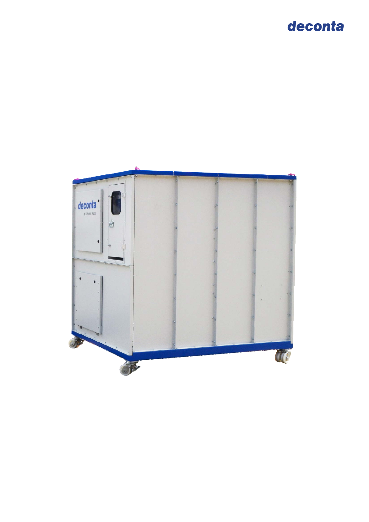
Compact 25.000
Manufacturer: deconta GmbH
Im Geer 20, D - 46419 Isselburg
Description / Type-No.: Compact 25.000 / Type 524, 532

Instruction manual
Compact 25.000
Seite 2
Table of contents
on page
1 Introduction 3
2 Basic Safety Advice 4
2.1 Intended use 4
2.2 Operation 4
3 Transport 5
3.1 Transport 5
3.2 Storage 5
4 Scope of delivery at Purchase and Rental 5
4.1 Scope of delivery 5
4.2 Return shipment after renting 5
5 Technical description 6
5.1 Intended use 6
5.2 Unit description 6
5.3 Control cabinet 7
5.4 Filter description / Classification 7
5.5 Information for filter change 9
6 Technical data 10
6.1 Fan guide line 10
6.2 Performance data 11
6.3 Filter system 11
6.4 Connections, Dimensions, Weights 11
7 Assembly instruction 12
8 Initial operation 13
8.1 Version with SRE control 13
8.2 Version with SE control 15
9 Maintenance and care 16
9.1 Maintenance 16
9.2 Filter control 16
9.3 Filter change 16
10 Double filtration 18
11 Circuit diagram 21
11.1 Version SRE Type 524 21
11.2 Version SE Type 532 22
12 Sound level measuring 23
13 Declaration of conformity 24

Instruction manual
Compact 25.000
Seite 3
1 Introduction
Thank you for choosing a deconta product!
With this device you obtain a practical solution with simple operation, which was
completed in a compact and functional way.
The deconta products guarantee:
Stability, Long life and aptness on site
Mechanics with „kick“
Pleasing design
The copyright of this instruction manual remains with deconta. This manual is intended
for assembly, operation and maintenance personnel. It contains instructions and drafts of
technical nature which may neither be distributed nor used in any unauthorised way for
competitive purposes or passed on to others.
For more information, please see our website www.deconta.com.

Instruction manual
Compact 25.000
Seite 4
2 Basic safety advices
The handling of the appliance technology is only allowed for instructed staff. The exact
knowledge of the guide book is an important condition for your staff in regard to the
handling of the machine.
2.1 Intended use
deconta has to engage you as the user to follow the guide book and to employ this
engineered technology only in accordance with the regulations and not in a inappropriate
way! In the event of non-observance, deconta assumes no liability.
2.2 Operation
In order to ensure the safety during the operation of the device, please respect, without
fail, the following:
Do not place in an explosive area
Necessary repairs, maintenance and cleaning, in particular in the field of electrical
equipment may only be realized by qualified staff
The safety and security equipments have to be treated with care, ready for use.
the indicated safety advices have to be kept in a readable state and have to be
observed
In order to ensure safety, any changes to the machine are prohibited.
ATTENTION!
The device is not suitable for the use in a condensed, corrosive, flammable and
explosive compartment air.
Express reference is made to the additional and national safety measures and
directives when operating the Equipment technology.
The control of the exhaust has to be effected during the initial operation as well as at
least in 3 years interval.

Instruction manual
Compact 25.000
Seite 5
3 Transport
3.1 Transport
To unload a crane a Minimum load of 1,3 tons is required. The unloading place should be
firm and flat.
Transport damages have to be documented at once during the handing over of the
carrier or another supplier. Please note the possible damages additionally on the way bill.
Available as option is a specially designed chassis allowing moving the machine on level
floors.
3.2 Storage
Storage in areas inaccessible to unauthorized persons only.
Seal the flap on the exhaust side.
Attach the transport lid at the sucking side and, if used filters are installed, seal
additionally with tape.
4 Scope of delivery at purchase and rental
4.1 Scope of delivery
The delivery of the Compact 25 000, regardless of whether a device is purchased or
rented, unless other arrangements have been made, contains:
N.P.U. Compact 25.000
Transport lid
Complete set of filters
25 m measuring tube (only with SRE version)
Instruction manual
4.2 Return shipment after renting
To protect our customers and in terms of dangerous goods transport regulations, we
must insist on following return delivery conditions:
thoroughly cleaned (ready for use)
without residual fiber bonding
completely as in 4.1 but without filter
without damage

Instruction manual
Compact 25.000
Seite 6
5 Technical description
5.1 Intended use
The negative pressure unit Compact 25.000 was built for the filtration of non-condensing
asbestos contaminated air, in temperature range up +45 °C, with external exhaust for the
air. During asbestos sanitation works within closed rooms, it must be avoided that
asbestos fibres leave the sanitation area and in this way endanger humans and the
environment. For these reasons, the sanitation areas (also called dirty area) have to be
separated from the clean area with the help of a negative pressure unit and kept under
dynamic negative pressure.
An integrated filtering system establishes the conditions that the asbestos concentration
in the exhausted air does not exceed max. 1000f/m³. The exhausted air is blown in the
open air.
The device is not appropriate for the filtration of flammable gas or dust.
5.2 Unit description
NPU as Container system
Effective air capacity 25000 m³/h
Automatic or manual negative pressure control (Version SRE)
Manual negative pressure control (Version SE)
3 filter stages consisting of HEPA filter, bag filter and pre-filter
Filter change from the outside
Manometer for filter control
Lockable control cabinet
Eye hooks
External dimensions 2150 x 1670 x 2240 mm (L x W x H)
Options:
Manual negative pressure control (SE-Control)
Sound damper
Chassis
Installation of further filter stages (double filtration)

Instruction manual
Compact 25.000
Seite 7
5.3 Control cabinet
5.4 Filter description / Classification
There is a 3 stage filtration unit integrated in this unit.
5.4.1 Prefilter:
Filter class pursuant DIN 24185 / EN
779 G4 / EU4
Frame Cardboard frame, 47 mm wide
Filter medium Synthetic
Degree of separation (Am) 90 %
Nominal rated current 5400 m³/h/m²
Nominal velocity in blower stream by
nominal volume 1,5 m/s
Difference of initial pressure 42 Pa
Recommended final pressure drop 250 Pa
Temperature / humidity 100 °C / 100 % RF (relative humidity)
Filter dimensions 610 x 610 x 47 mm
SRE-Control
Operationg hours counter
Ground connection
Power connection
Main switch
Monometer
Filter control
Mains indicator lamp
Connectioin Atmosphere
Connection Negative
pressure

Instruction manual
Compact 25.000
Seite 8
5.4.2 Bag filter:
Filter class pursuant DIN EN 779 F5
Degree of separation (Am) 96 %
Nominal rated current 3400 m³/h
Difference of initial pressure 55 Pa
Recommended final pressure drop 250 Pa
Temperature / humidity 55 °C / 100 % RF (relative humidity))
Filter area 2,3 m²
Filter dimensions 592 x 592 x 330 mm
5.4.3 Main filter:
Frame Plastic
Filter medium Glass fibre
Sealing compound Polyurethan
Seal Polyurethan, foamed
Filter area 31 m²
Filter class H13 pursuant EN 1822
Degree of separation > 99,95 % im MPPS leak tested
(Most Penetraded Partikel Size)
Temperature / humidity 110 °C / 100 % RF (relative humidity))
Filter dimensions 610 x 610 x 292 mm
Handle protection Expanded metal gratings, both sides

Instruction manual
Compact 25.000
Seite 9
5.5 Information for filter change
The frequency of the change of filter depends on the degree of pollution of the filter. If the
sealing up of the filter increases (contamination of the filter), the air capacity decreases.
For the control of the filter during the operation, the device is equipped with a
manometer.
Important: Use only authorised, faultless filter!
With filter in new state, approximately 650 Pascal are displayed on the gauge.
(Evaluated at 100 % capacity)
We recommend a filter change at about 1300 Pascal (indicator light filter monitoring is
on)
To determine which filter (main filter, bag filter or pre-filter)at a Manometer value of
about 1300Pascal, is dirty, do the following:
1. Renew the pre and bag filter and switch the device on
2. Pressure gauge value 950 - 1150 Pascal => continue to operate the device
3. Pressure gauge value > 1150 Pascal => renew the main filter

Instruction manual
Compact 25.000
Seite 10
6 Technical data
All data on air performance and volume flows are taking into account a measuring
tolerance of ± 15% based on the measuring range end value, determined in a multi-point
measuring method with a calibrated vane anemometer.
6.1 Fan guide line
0
500
1000
1500
2000
2500
3000
5000 8000 10000 15000 20000 25000 30000
Volumenstrom in m³/h
Druckdifferenz in Pa
Technical data:
Voltage: 400 V
Frequency: 50 Hz
Speed: 2750 U/min
Max. air temperature: 45°C

Instruction manual
Compact 25.000
Seite 11
6.2 Performance data
Air capacity with filters 25000 m³/h
Power connection 400 Volt, 50 Hz
Current consumption 30 Ampere
Motor-Power 18,5 KW
6.3 Filter system
3-stage:
Pre-filter EU 4, 610 x 610 x 47 mm
Bag filter F5, 592 x 592 x 360 mm
HEPA-Filter pursuant EN 1822 Class H13, 610 x 610 x 292 mm
6.4 Connections, Dimensions, Weights
Power connection 400 Volt, 32 Ampere
CEE- connector plug 5-pin
Length x Width x Height 2150 x 1670 x 2240 mm
Total weight approx. 1220 kg
Technical changes reserved

Instruction manual
Compact 25.000
Seite 12
7 Assembly system
This NPU comes ready from the factory and is intended for immediate operation.
Do not operate unit, if it is visibly damaged. Please inform deconta GmbH immediately.
Connect the container to the sanitation area
Seal the container with the sanitation area
Ensure that sufficient fresh air arrives in the sanitation area
Connect earth to ground connector (see picture on page 7)
Remove transport lid
Fully open the exhaust air damper

Instruction manual
Compact 25.000
Seite 13
8 Initial operation
8.1 Version with SRE control
SRE is a control electronic for Negative Pressure Units. The SRE-control measures
permanently via a measuring tube the actual negative pressure in the sanitation area and
controls according to its specifications the Negative Pressure Unit automatically. The
requested negative pressure can be maintained constantly.
Control panel:
Set point in Automatic operation
Operating mode (AUTO or MANU)
Measured negative
pressure
LED Filter change
Fan capacity in %

Instruction manual
Compact 25.000
Seite 14
Starting position:
Connect to power
Chose a measuring point in the dirty area and connect the PE-tube 8 x 1 to the
negative pressure connection
Chose the measuring point in the clean area (adjoining room) and connect the PE-
tube 8 x 1 to the connection atmosphere
The unit is now ready for use.
Power switch to „ON“
Press key ON/OFFIMPORTANT: Press and hold the key for about 3 seconds
The last saved mode (AUTO / MANU)is automatically set and the fan starts
Automatic operation
In automatic operation the set value for the negative pressure in Pascal is entered with
the buttons „+“ and „-“ (display set value in automatic operation). By comparing the
entered set value with the permanently measured actual value (measured negative
pressure) the speed of the fan is automatically adjusted, i.e. the fan moves automatically
“up” or “down”.
Manual operation:
In manual operation the fan capacity is set with the buttons „+“ and „-“. The performance
in % and the measured negative pressure are shown in the display. In manual operation
the machine does not adjust automatically!
In case of power failure the control saves the date set last, starts after recovery
automatically and re-establishes the saved data.
Connection
A
tmos
p
here Connection
Ne
g
ative
p
ressure

Instruction manual
Compact 25.000
Seite 15
Switching off
Press ON/OFFIMPORTANT: Keep the button pressed for about 3sec.
The unit down-regulates automatically . Switch off the main switch after approx. 40sec.
8.2 Version with SE control
The negative pressure unit is as standard supplied with a manual infinitely variable
control. The desired negative pressure is set via the manual power control and/or via the
air supply in the contaminated work are.
Connect to power supply
Switch on main switch
Turn controller
In case of power failure the negative pressure unit starts automatically after recovery.

Instruction manual
Compact 25.000
Seite 16
9 Maintenance and care
9.1 Maintenance
The ventilator plants (deduster, industrial vacuum cleaners and devices for the de-
aeration or keeping under negative pressure) have to be overhauled or controlled once a
year at least or if necessary by an expert. The Test result must be produced on request.
9.2 Filter control
During the operation the filter state has to be controlled as described under 5.5
9.3 Filter change
Attention:
Contaminated filters have to be changed under all corresponding safety
measures (see TRGS 519)
Filter change only when unit is switched off.
Use approved filters only
Do not use bonding agents on the machine
Change of Prefilter:
Gently remove and discard the filter
Insert the new filter
Change of Bag filter:
Open pressure spring
Remove the bag filter
Insert the new filter
the bags should be vertical
Lock pressure spring again
Pressure s
p
rin
g
Ba
g
filte
r

Instruction manual
Compact 25.000
Seite 17
Change of Main filter:
Remove Pre- and Bag filter
Unscrew fixing screws of Prefilter and Bag filter frame. Remove whole frame.
Loosen nuts of clamping bar and remove clamping bars.
Remove Main filter and discard
Check and clean the sealing surfaces on the unit
Insert the new HEPA filter
Reattach clamping bar
Attach Pre-and bag filter frame and insert filter.
Important:
Main filters must be handled with care. Damages can neutralise the effectiveness
of the filtration.
Hoses and filters are contaminated at first use. Repairs and maintenance work may
only be carried out under compliance with the strictest safety measures.
Fixing screws
Clamping bar
Nut

Instruction manual
Compact 25.000
Seite 18
10 Double filtration
To install a second main filter level (double filtration), proceed as follows:
Remove Pre- and Bag filter
Unscrew clamping bolts of Pre- and Bag filter frame and remove whole frame
Loosen nuts and remove clamping bar
Clamping bolts
Clamping bar
Nut

Instruction manual
Compact 25.000
Seite 19
Remove screws of clamping device
Attach extensions to the Clamping device and bolt together (the extensions are at
the side walls)
Screws
Clamping device
Extension
Mounting with extensions

Instruction manual
Compact 25.000
Seite 20
Insert two main filters one behind the other
Fasten clamping bar
Fix Pre-and Bag filter frame and insert filters
Clamping bar
1. Main filtration
2. Main filtration
Table of contents
Other deconta Industrial Equipment manuals
Popular Industrial Equipment manuals by other brands

Festo
Festo CPE 3/2-PRS/RP3/H3-SET Series Assembly instructions

Meyrat
Meyrat MHF-19 Assembly instructions

Grundfos
Grundfos SMD Installation and operating instructions

Expleco
Expleco GLAFS MAXI instruction manual

Eastey
Eastey SB-2 HD user guide

Schenker
Schenker Modular 100 230V Electron digital Operation and maintenance manual

Festo
Festo VTSA Series manual

Johnson Controls
Johnson Controls Frick AcuAir Installation operation & maintenance

Berthold
Berthold EmulsionSENS technical information

BVA Hydraulics
BVA Hydraulics HD3020 instruction manual

VOLTCRAFT
VOLTCRAFT VC-CJS61 operating instructions

AeroFlow
AeroFlow AF82-2012 installation manual