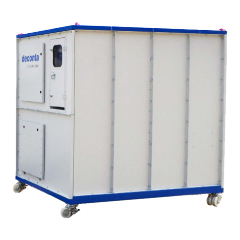
deconta D 610 User manual

Instruction manual
Negative pressure unit
D 610
in ex-protection design
Manufacturer: deconta GmbH
Im Geer 20, 46419 Isselburg
Description / Type-No.: Negative pressure unit D 610 in ex-protection design
Typ 418
Serial-No.: .................

Instruction manual
Negative Pressure Unit D 610 EX
Seite 2
Table of contents
on page
1
Introduction
3
2
Basic safety advice
4
3
Transport und storage
5
3.1
Delivery
5
3.2
Transport
5
3.3
Storage
5
4
Volume of delivery at purchase and rent
5
4.1
Volume of delivery
5
4.2
Return delivery after renting
6
5
Technical description
6
5.1
Intended use
6
5.2
Unit description
7
5.2.1
Control ON/OFF
8
5.3
Filter description / classification
9
5.4
Filter change
10
6
Technical data
11
6.1
Fan characteristic curve
11
6.2
Performance data
12
6.3
Connections, Dimensions, Weights
12
6.4
Power loss in hose lines
13
6.5
Resistor diagram for hose lines
13
7
Assembly instructions
14
7.1
Negative pressurisation
14
7.2
Assembly of optional attachment housing
15
8
Initial operation
16
9
Maintenance
17
9.1
Maintenance
17
9.2
Filter control
17
9.3
Pre- and intermediate filter change
17
9.4
Main filter change
18
10
Possible failures and their repairs
19
11
Circuit diagram
20
12
Sound level measuring
21

Instruction manual
Negative Pressure Unit D 610 EX
Seite 3
1 Introduction
Thank you for choosing a deconta product!
With this device you obtain a practical solution with simple operation, which was completed
in a compact and functional way.
The deconta products guarantee:
•Stability, Long life and aptness on site
•Mechanics with „kick“
•Pleasing design
•Command with technical „acuteness“
With products of deconta you are sure to be one step ahead of your competitors.
As a result of our experiences in the asbestos removal industry our equipment technology
is designed according to current safety standards TRGS 519.
For your protection, the use of the equipment technology outside of the asbestos removal
should be agreed upon beforehand with deconta. With pleasure deconta will be of
assistance and will then take liability beyond the original use.
In case of damage (mechanical or electrical) or a malfunction, the deconta-express service
can remedy the situation in a short term.
Be aware that the non-observance of this instruction manual causes the expiration of your
warranty claims.
The copyright of this instruction manual remains with deconta. This manual is intended for
assembly, operation and maintenance personnel. It contains instructions and drafts of
technical nature which may neither be distributed nor used in any unauthorised way for
competitive purposes or passed on to others.

Instruction manual
Negative Pressure Unit D 610 EX
Seite 4
2 Basic safety advice
As an operator, you are obliged by deconta to follow the instruction manual and to use this
engineered technology equipment only in accordance with the regulations and its suitability!
In the event of non-observance, deconta assumes no liability.
The handling of the appliance technology is only allowed for instructed staff, because you
have to consider the contaminated materials and devices as dangerous goods. The exact
knowledge of the instruction manual is an important condition for your staff before handling
the machine.
We explicitly point out the legally required safety measures during assembly and
dismantling as well as when maintaining the equipment technology.
Necessary repairs, maintenance and cleaning, in particular in the field of electrical
equipment should be performed by qualified staff or if necessary by the express service
deconta in order to guarantee the function and safety.
The safety and protective equipment has to be treated with care and the indicated safety
advice has to be kept in a readable state.
The installation and the operation of the device can only be executed according to the
instruction manual or after consultation with deconta.
In order not to restrict safety, any changes to the machine are prohibited. Changes can only
be made with the agreement of deconta.
Supplementary to this instruction manual, the standard, legal and remaining binding rules
concerning the accident prevention and the protection of the environment have to be
observed.
The control of the exhaust has to be effected during the initial operation as well as at least
in a 3 years interval.

Instruction manual
Negative Pressure Unit D 610 EX
Seite 5
3 Transport and storage
3.1 Delivery
In order to protect the device against climatic influences it is wrapped with a plastic film.
Transport damages have to be documented at once during the handing over of the carrier
or another supplier. Additionally please notate the possible damages on the way bill.
3.2 Transport
Transport the device only in a decontaminated state.
The device can be transported by one person.
For the easy handling, the device has got carry handles.
3.3 Storage
Store the device only in a decontaminated state.
In order to avoid damages, the installation has to be kept in a dry location with no access
for unauthorized persons.
4 Volume of delivery at purchase or rent
4.1 Volume of delivery
Regardless if the unit is purchased or rented, unless no other agreements have been
made, the volume of delivery of the negative pressure unit D610 consists of:
•Unit D 610
•Instruction manual
•Compete filter set
•Packaging

Instruction manual
Negative Pressure Unit D 610 EX
Seite 6
4.2 Return delivery after renting
For the protection of our clients and in accordance with the rules for hazmat transport, we
must insist on the following return delivery conditions:
•cleaned thoroughly (ready for use)
•completely free of adhesive remains
•complete, as described under 3.1 however without filter set
•without damages
5 Technical description
5.1 Intended use
Negative pressure unit with integrated 3 stage filtration unit to filtrate asbestos
contaminated room air.
The unit specially designed for the use in the contaminated area.
Over-pressure technology prevents the intrusion of contaminated ambient air into the
housing.
The negative pressure unit Compact 5.500 in ex-protection design may be utilized in
areas endangered by gas explosion Zone 2 according to EN 60079-10, whereas
additional national regulations have to be observed.
During asbestos sanitation works within closed rooms, you must avoid that asbestos fibres
leave the sanitation area and endanger human health and the environment. For these
reasons, the sanitation area (also called dirty area) has to be separated from the clean area
with the help of a negative pressure unit and kept under dynamic negative pressure.
An integrated filtering system establishes the conditions that the asbestos concentration in
the exhaust air does not exceed max. 1000F/m³. The exhaust air is blown into the open.
The segments used comply with the following standards:
•Motor Ignition protection type increased safety „e“ according to EN 60079-7
Asset group IIB
Temperature class T5
•Motor protection Ignition protection type flameproof enclosure „d“ according to EN 60079-1
device Asset group IIC
Temperature class T6
•CEE- Ignition protection type flameproof enclosure „d“ according to EN 60079-1
Connector Asset group IIC
Temperature class T6

Instruction manual
Negative Pressure Unit D 610 EX
Seite 7
5.2 Description D 610
The negative pressure unit D610 features powder-coated housing made of hard aluminium,
in which an electric fan, a main filter, an intermediate filter and a pre filter find a place.
There is hose connection on the extract side (filtered air).
On the device there is a manometer for the filter control during operation.
Functional principle:
Überdruck
kontaminierte
Luft
gereinigte
Luft Ventilator S-Filter
Highlights:
•Designed for the use in the contaminated work area
•Housing seal due to overpressure technology
•Smooth and easy-to-decontaminate housing
•Sturdy and light housing
•3-fold sealed Hepa filter
•Hepa filter according to EN 1822 classification H13
•Simple and low emission filter change
•Filter change in 3 minutes
•The filter change is indicated optically on a manometer
•Rustproof and powder coated housing
•infinitive variable control 0 - 100% (SE and SRE)
•automatic soft starting, also after a power failure
•all operation and function elements are shock-protected
•stackable housing, ergo minor floor space
•Power optimised fan with high capacity
Options:
Attachment housing for the second hepa filter (Double filtration)
Attachment housing for pocket filter
Acoustical indication for the filter change

Instruction manual
Negative Pressure Unit D 610 EX
Seite 8
5.2.1 Control ON / OFF
The Unit D610 is delivered in series with an ON / OFF control for the power regulation.

Instruction manual
Negative Pressure Unit D 610 EX
Seite 9
5.3 Filter description / classification
Integrated in the unit is a 3-step filtering combination.
In particular:
Pre and intermediate filter
Pre-filter
Intermediate filter
Filter class pursuant DIN 24185 / EN 779
G3 / EU3
G4 / EU4
Frame
Cardboard frames,
48 mm wide
Cardboard frames,
48 mm wide
Filter medium
Glass fibre
Synthetic
Degree of separation(Am)
85 %
90 %
Nominal rated current
5400m³/h/m²
5400m³/h/m²
Nominal velocity in blower stream at
nominal volume
1,5 m/s
1,5 m/s
Difference of initial pressure
30 Pa
42 Pa
Recommended difference of final pressure
450 Pa
250 Pa
Temperature / Air humidity
100°C/100% RF
(relative humidity)
100°C/100% RF
(relative humidity)
Filter dimensions
610x610x47
610x610x47
Main filter, Hepa filter (S)
Frame
12-fold glued wood frame
Or plastic frame
(moisture-proof)
Separator
Aluminium
Filter medium
Glass fibre
Sealing mass
Polyurethan
(2-Component-Glue)
Seal
Polyurethane, foamed
Filter area
31 m²
Filter class
H13 according to DIN EN 1822
Degree of separation(
>99,95% im MPPS leak tested
(Most Penetrated Particlel Size)
Temperature / Air humidity
110°C/100% RF
(relative humidity)
Filter dimension
610x610x292

Instruction manual
Negative Pressure Unit D 610 EX
Seite 10
5.4 Filter change
The frequency of the change of filter depends on the degree of pollution of the filter. If the
sealing up of the filter increases (contamination of the filter), the air capacity decreases.
For the control of the filter during the operation, the device is equipped with a manometer
(see image).
Important: Use only approved, faultless filter!
•In a new condition of the filter the manometer reads approx. 650 Pascal. (Analysed at
100 % capacity)
•We recommend a change of filter at approx. 1000 Pascal.
Optionally, the device can be equipped with an acoustic signal (horn), which indicated the
clogging of the filter.

Instruction manual
Negative Pressure Unit D 610 EX
Seite 11
6 Technical Data
6.1 Fan characteristic curve
Technical Data:
Voltage: 400 V
Frequency: 50 Hz Air discharge: 6000 m³/h free exhaust
Speed: 2800 U/min max. discharge temperature: 45°C

Instruction manual
Negative Pressure Unit D 610 EX
Seite 12
6.2 Performance data
Air performance free-blowing 6.000 m³/h
Air performance with 1x S-filter 4.500 m³/h
Air performance with 2x S-filter 4.000 m³/h
Power connection 230 Volt, 50 Hz
Power consumption 16 Ampere
Power 3 KW
Filter system 3-stage
Pre filter EU 3dimensions: 610 x 610 x 047
Intermediate filter EU 4dimensions: 610 x 610 x 047
Main filter dimensions: 610 x 610 x 292
6.3 Connections, Dimensions, Weights
Total weight (without filter) 72 kg
Length x Width x Height 1020 x 690 x 850 mm
Power connection 400 Volt, 16 Ampere, CEE-plug
Exhaust air hose connection electively 400 or 450
Suction hose connection optionally 400 or 450
6.3.1 Attachment housing
Total weight (without filter) 10 kg
Length x Width x Height 290 x 690 x 690 mm

Instruction manual
Negative Pressure Unit D 610 EX
Seite 13
6.4 Power loss in hose lines
Following factors have adverse influence:
•Hose lines too long
•Bends and bows in the hose lines
•Cross-section narrowing of the hose lines.
6.5 Resistance diagram for hose lines
•Hose line with external spiral
•Sleeky inside
•in 10 mtr. Length

Instruction manual
Negative Pressure Unit D 610 EX
Seite 14
7 Assembly instructions
The negative pressure unit is delivered ex-works and ready for immediate operation.
If there are visible damages, do not operate the device.
Please contact the deconta GmbH at once.
7.1 Negative pressurisation
Optionally the negative pressure unit can be operated in the contaminated working area or
connected to the working area from the outside.
Operation in the contaminated working area
•Set up unit in the working area
•Direct exhaust air hose into open air
•Provide for enough supply air in the working area (opening approx. 600 mm x 600 mm
diagonally to negative pressure unit)
Operation outside of the contaminated working area
•Connect the device with the wall between clean / and contaminated working area
•Place it about. 100 mm into the working area
•Seal the device with the wall
•Direct the exhaust air hose into the open air
•Provide for enough supply air in the working area
Clean area
Contaminated area
Supply air opening with
self-closing flaps

Instruction manual
Negative Pressure Unit D 610 EX
Seite 15
7.2 Assembly of the optional attachment housing (SNAP)
Optionally for a second Hepa filter (Double filtration), additional activated carbon filter or
pocket filter
•Dismount the pre filter and unscrew the safety corners
•Place the attachment housing and fix the tension locks
•Insert the Hepa filter / activated carbon filter
•Fix the tension frame by means of screws
•Insert the pre filter
By using an activated carbon filter, this should be inserted in the negative pressure unit and the
Hepa filter in the attachment housing.
Safety corner
Tension lock

Instruction manual
Negative Pressure Unit D 610 EX
Seite 16
8 Initial operation
Vor jeder Inbetriebnahme in gasexplosionsgefährdeten Bereichen das Gerät auf
„Schleifgeräusche“ am Lüfter untersuchen.
Sollten Sie diese feststellen, darf das Gerät nicht in Betrieb genommen werden!
The negative pressure unit D 610 is delivered in series with an ON / OFF switch.
•Connect to power
•Turn ON/OFF switch
Negative pressurisation
•Adjust the desired negative pressure at the supply air opening
Negative pressure too high: open the supply air opening
Negative pressure too low: shut the supply air opening

Instruction manual
Negative Pressure Unit D 610 EX
Seite 17
9 Maintenance
9.1 Maintenance
The ventilator plants (deduster, industrial vacuum cleaners and devices for the deaeration
or negative pressurisation) have to be overhauled or controlled once a year at least or if
necessary by an expert. The result of the inspection is to be submitted on request.
9.2 Filter control
During operation control filter conditions, as described under 5.4.
9.3 Change of pre and intermediate filter
Attention:
•Contaminated filters has to be changed under all corresponding safety measures
•Filter change only when machine is switched off
•Use only approved filters
•Do not use bonding agents on the machine
Pre and intermediate filter change:
•Carefully remove filter and dispose of it
•Insert new filter

Instruction manual
Negative Pressure Unit D 610 EX
Seite 18
9.4 Change of Hepa filter
Attention:
•Contaminated filters has to be changed under all corresponding safety measures
•Filter change only when machine is switched off
•Use only approved filters
•Do not use bonding agents on the machine
Remove the Hepa filter:
•Remove the pre filter
•Unscrew the hexagone screws M8 and remove the tension frame
•Remove the Hepa filter and dispose of it professionally
Insertion of the Hepa filter:
•Control the sealing face of the machine and clean.
•Clean the inside of the housingI
•Insert the new filter in the middle
•Tighten the tension frame and the hexagone screws M8 (tighten the screws carefully)
•Insert the pre filter
Important:
The Hepa filter must be treated with care, damages can suspend the effectivity of the
filtration.

Instruction manual
Negative Pressure Unit D 610 EX
Seite 19
10 Possible failures and their repairs
Failure
Possible reason
Repair
Negative pressure to
low
Pre- / intermediate
filters dirty
Change of filters as described under
9.3 and 9.4
Device does not work
Power source out of
order
Have power source examined and
repaired by an expert.
Device does not work
Components of the
Neg Air are defective
Have the device repaired by deconta or
an accredited workshop..

Instruction manual
Negative Pressure Unit D 610 EX
Seite 20
11 Circuit diagram
This manual suits for next models
1
Table of contents
Other deconta Industrial Equipment manuals


