4
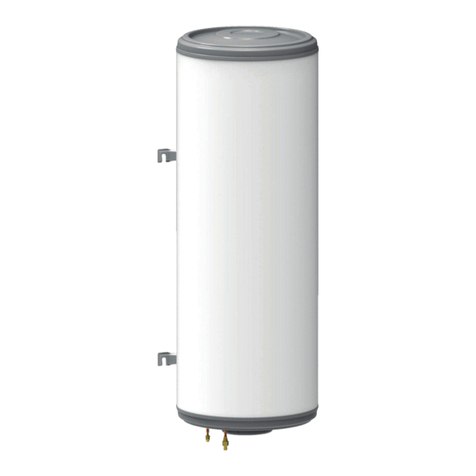
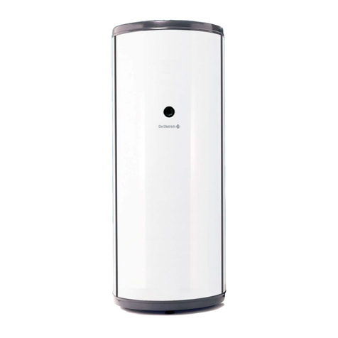
4. Standard vertical wall-mounted water heaters
Type of water heater
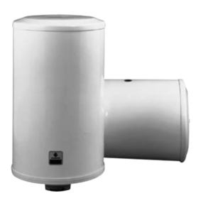
STANDARD VERTICAL WALL-MOUNTED HEATER
Nominal capacity litres 50 75 100 150 200
Nominal power watts 900 1200 1200 1800 2400
Heating time (1) 3:55 hr. 4:30 hr. 5:30 hr. 5:25 hr. 5:30 hr.
Maintaining consumption
kWh per 24 hours at 65˚C (2) 0.72 0.78 0.96 1.11 1.33
Cooling constant
Wh per 24 hours / litre / ˚C 0.35 0.24 0.23 0.18 0.17
Category (as per 1989
Thermal Equipment regulations) – – B-20 % B -20 % B -20 %
Main dimensions
Amm156 120 113 146 473
Bmm––500 800 800
Dmm370 572 750 1050 1050
Hmm576 742 913 1246 1573
H with optional stand mm – 1234 1405 1738 2065
Weight without water kg 23 29 33 43 52
(1) As per standard NFC 73 221 (15˚C to 65˚C).
(2) As per French Standard.
Fastening
Vertical wall-mounted water heaters are fastened with 4 bolts, dia.
10, sealed into the wall.
A drilling template is supplied with the unit to make it easier to mark
the drilling holes without any need to take measurements.
Two clamps fitted with notches (supplied with the unit) allow easy
fastening. The heater is packed upside down and placed on a poly-
styrene packing piece. In this way, the various parts are kept acces-
sible and it is easier to fit the clamps.
(*) Note: 50 L and 75 L heaters are fastened with only two bolts. The lower
clamp is replaced by a stop.
Stand: 75, 100, 150 and 200 L Standard vertical wall-mounted
water heaters may be placed on the floor on a stand designed for
standard vertical models which is available as an option. We recom-
mend that you fasten the upper clamp to the wall.
Electrical connections
Vertical wall-mounted water heaters are designed for a single-
phase 230 VAC power supply. The coupling of multiple voltage hea-
ters is user-modifiable, and may also be set for three-phase 230 V
or 400 V power supplies.
The metal parts must be grounded (with the special terminal on the
unit). The section of the line, the omnipole breaking device and the
protection system (fuses or circuit-breakers) shall be selected in
keeping with applicable standards, depending upon the input inten-
sity, voltage and power.
Note: The heaters must necessarily be connected to a fixed piping system. In prin-
ciple, power will be supplied to the heater at night, manually or automatically with the
help of a clock supplied by the electricity company. In this way, the water is heated
when the reduced off-peak rate is charged for electricity. The unit may be fitted with a
switch for supplying power in the daytime, when the full rate is charged.
Type of water heater STANDARD VERTICAL WALL-MOUNTED HEATER
Capacity litres 50 75 100 150 200
Power supply single single single single multiple single multiple
Section mm21,5 1,5 1,5 1,5 1,5 2,5 2,5
Single-phase 230 V Intensity Amp 3,9 5,2 5,2 7,8 7,8 10,4 10,4
Section mm2––––1,5–1,5
Three-phase 230 V Intensity Amp ––––4,5–6
Section mm2––––1,5–1,5
Three-phase 400 V Intensity Amp ––––2,6–3,5
Hydraulic connections
The connections are marked with blue (cold water) and red (hot
water) discs. Fitting a stop valve on the cold water supply pipe is
compulsory.
Safety rules require that a lead-sealed safety valve calibrated to 7
bar must necessarily be fitted on the cold water supply pipe (for the
guarantee to operate). We recommend the use of diaphragm type
hydraulic safety units bearing the NF mark. A pressure reducing
valve must be fitted if the supply pressure is greater than 5.5 bar.
Example of installation
Pressurised heater
Type of heater
STANDARD VERTICAL WALL-MOUNTED HEATER
Capacity litres 50 75 100 150 200
14 x 16
Copper pipe dimensions mm 12 x 14 or 14 x 16 or
16 x 18
Note : The composite material connecting piece (supplied in a bag) is to be
fitted on the hot water outlet of the heater. It is used to prevent the formation
of a galvanic couple, which can lead to the corrosion of the connection
threads when the heater is connected directly to copper or brass.
