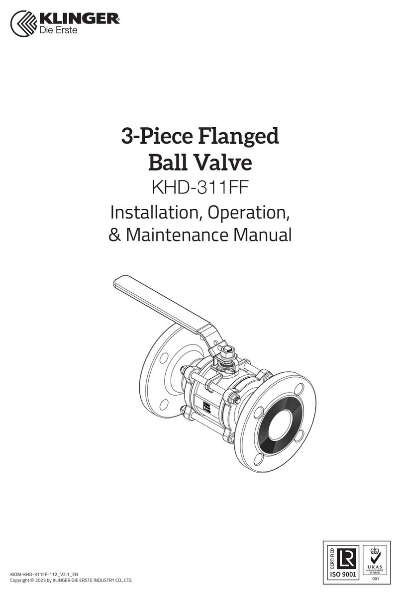
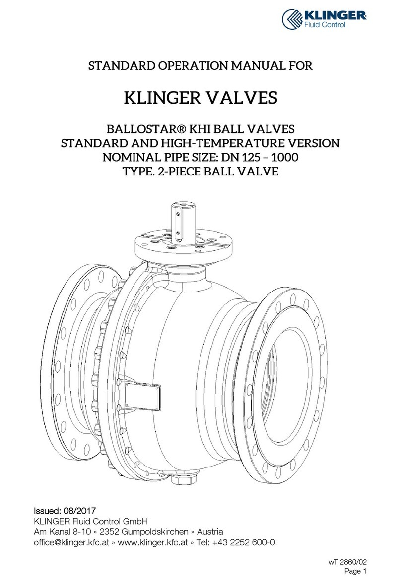
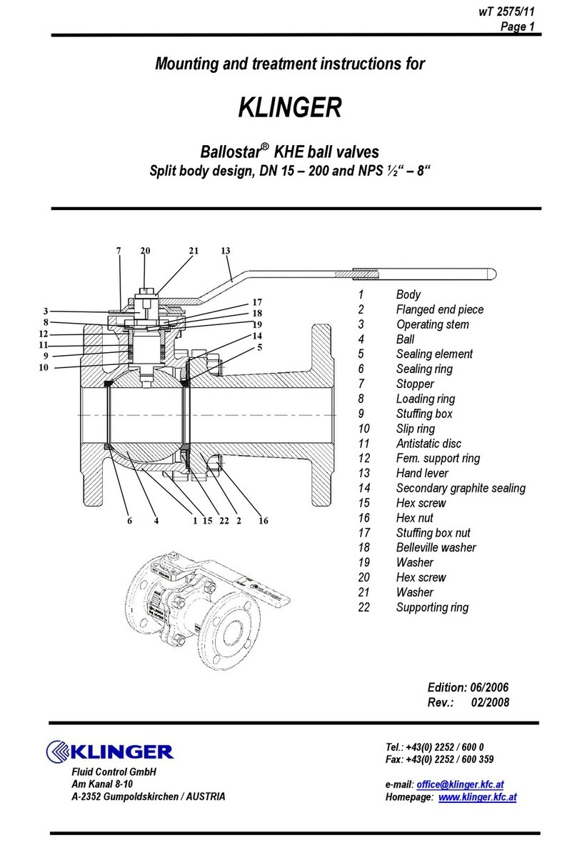
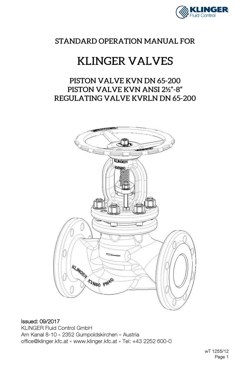
KLINGER KHD-M4F Series Instruction manual

IOM-Series KHD-M4F(a)-110_V1.0_EN
Copyright © 2022 by KLINGER DIE ERSTE INDUSTRY CO., LTD.
Installation, Operation,
& Maintenance Manual
Direct Mount 4-Seated
3-Way Flanged Ball Valve
Series KHD-M4F(a)

IOM-Series KHD-M4F(a)-110_V1.0_EN
Copyright © 2022 by KLINGER DIE ERSTE INDUSTRY CO., LTD. 32 IOM-Series KHD-M4F(a)-110_V1.0_EN
Copyright © 2022 by KLINGER DIE ERSTE INDUSTRY CO., LTD.
Direct Mount 4-Seated 3-Way
Flanged Ball Valve M4F(a)
Direct Mount 4-Seated 3-Way
Flanged Ball Valve M4F(a)
Table of Contents Chapter I
Introduction
The manual is provided to ensure proper installa-
tion, operation & maintenance for Series M4F(a)
Direct Mount 4-Seated 3-Way Flanged Ball Valve,
manufactured and supplied by KLINGER DIE ERSTE
Industry Co., Ltd. The valves are identified by mark-
ing on the body or on a name plate or both.
1.1 Contact Information
For information concerning warranties, or for ques-
tions pertaining to installation, operation or mainte-
nance of KLINGER DIE ERSTE products, contact:
KLINGER DIE ERSTE INDUSTRY CO., LTD.
5F-1, No.936, Sec. 4, Wen-Xin Road,
Taichung City, Taiwan 406
Phone: +886 4 22310059
Fax: +886 4 22360236
Email: [email protected]
To order replacement parts, contact KLINGER DIE
ERSTE sales at address listed above.
1.2 General Notes
The following instructions refer to Series M4F(a)
Direct Mount 4-Seated 3-Way Flanged Ball Valve as
described in the KLINGER DIE ERSTE current cata-
log.
Keep the protective covers in place until the valve is
ready for installation. Valve performance depends
upon prevention of damage to ball surface. After re-
moving the cover make sure that the valve is com-
pletely open and free of obstructions, dirt, particles
or any materials that may cause seat or seal dam-
age.
Valves may contain a silicon-based lubricant for
transportation, which aids in the assembly of the
valve. Lubricant may be removed with a solvent if
found objectionable. Alternatively valves can be or-
dered free of lubricants upon request.
Certain ferrous valves contain phosphate material,
and are oil dipped during the course of manufac-
ture. However, the processes used are completely
non-toxic.
I Introduction
1.1 Contact Information
1.2 General Notes
1.3 Precautions and Warnings
1.4 Storage
II Installation
2.1 General Notes
2.2 Installation of Ends
2.3 Pneumatic and Electrical Connections
III Operation
3.1 Handling
3.2 Cleaning
3.3 Manual Operation
3.4 Remote Operation
3.5 Technical Data
3.6 Limitation of Flow Direction
IV Maintenance
4.1 General Notes
4.2 Maintenance Frequency
4.3 Disassembly
4.4 Reassembly
4.5 Troubleshooting
4.6 Technical Data and Product Information
3
3
3
3
4
4
4
5
5
6
7
7
7
7
7
8
9
9
9
9
10
11
12
1.3 Precautions and Warnings
Choose the correct material of valve for different
applications before obtaining the valve. The user
should be aware of the operating situation, fluid
properties, and the possible outcomes when imple-
menting valves into the pipeline system. KLINGER
DIE ERSTE suggests that the user should make es-
timation beforehand.
Fluid undergoes property changes with respect
to outside factors, particularly fluid left inside the
sealed cavity. When temperature and pressure ex-
ceed allowable value, valve failure may occur.
The Series M4F(a) Direct Mount 4-Seated Flanged
3-Way Ball Valve are generally not recommend for
throttling services, due to both fluid flow and ball
leading edge may damage or deform the resilient
ball seats, and consequently causing leakage prob-
lem. Further, high fluid velocity or the presence of
solid particles in suspension will further reduce seat
life in throttling applications.
Do not attempt to remove the bonnet from the body
during operation, especially with the presence of
high pressure in the pipeline system.
For safety concern, unstable fluid should not be
used in the pipeline system, unless otherwise spec-
ified with the category III in Declaration of conformi-
ty.
CAUTION:
Before removing valve from pipeline, operator
should be aware of that: media flowing through
the valve may be corrosive, toxic, flammable, or
of a contaminant nature. Where there is evidence
of harmful fluids having flowed through the valve,
the utmost care must be taken. It is suggested
that the following safety precautions should be
taken when handling valves.
1) Always wear eye shields.
2) Always wear gloves and footwear.
3) Wear protective headgear.
4) Ensure that running water is readily accessible.
5) Fire extinguisher must be obtainable if media is
flammable.

IOM-Series KHD-M4F(a)-110_V1.0_EN
Copyright © 2022 by KLINGER DIE ERSTE INDUSTRY CO., LTD. 54 IOM-Series KHD-M4F(a)-110_V1.0_EN
Copyright © 2022 by KLINGER DIE ERSTE INDUSTRY CO., LTD.
Direct Mount 4-Seated 3-Way
Flanged Ball Valve M4F(a)
Direct Mount 4-Seated 3-Way
Flanged Ball Valve M4F(a)
Chapter II
Installation
Flush the pipeline carefully before installing the
valve. The particles of dirt or debris or welding may
damage the ball sealing surface and seats. Also, be-
fore installing, check all valve and mating flanges to
ensure gasket surfaces are free from defects.
2.1 General Notes
1) Direction
User must define the preferred mounting orienta-
tion with respect to the system pressure. The mark-
ing on the top of stem and handle help to identify
the upstream side (high pressure) and downstream
side (low pressure).
Note:
The pattern and flow direction of the ball will be ex-
actly marked on the top of valve stem. The marking
on the handle is ONLY for initial reference when re-
ceiving the goods. The user may change the instal-
lation of the handle, and invalidate the markings on
the handle, resulting in erroneous flow control.
Figure 2.1.1 The L-Port marking on the top of stem and
initial installation of handle.
2) Position
The body, cap and gasket are in the connection area
of ball valve and pipeline. The bear weight ability
and gradient are very important to the pipe instal-
lation. Do not make the pressure from the pipeline,
and stress to concentrate on the connecting area of
body and cap. Ball, seat, and stem will be damaged.
Consequently, deformation and leakage may occur.
Note:
Considering the balanced force of the valve seat,
DIE ERSTE recommends the use of a horizontal po-
sition when installing the 3-way ball valves which
size < DN80 (3”) to maximize sealing and reduce ac-
cumulation of particles.
3) Fittings
Select the correct size of fittings according to the
pipeline specification. Mating the valve to the pipe-
line adequately with appropriate bolts. Do not at-
tempt to correct pipeline misalignment by means of
flanged bolting.
Note:
Over tightening of any side may cause leakage.
4) Systems hydrostatic test
Before delivery, valves are tested 1.5 times the al-
lowable pressure at ambient temperature in OPEN
position. However, after installation, the piping sys-
tem may subject to system tests, as condition not
to exceed the marking pressure.
5) Pre-Installation Wash
Before the valve installation, clean the pipeline sys-
tem to remove any foreign deposits by water. Clean
the connecting flanged end surfaces as well to en-
sure tight sealing.
2.2 Installation of Flanged Ends
1. Before installing the valves, make sure the
flanges and the pipe are free from grit, dirt or
burrs.
2. The flanges must be aligned and parallel with
the correct distance to allow the valve face-to-
face dimension and gaskets to fit between.
3. Tighten the flange bolts in a crossover pattern,
with a torque values determined by the gasket
manufacturer, other variables like gasket type
and material, bolt, flange and lubricant affect the
tightening torque values.
4. Note that the bolts tightening must be uniform
in order to create a parallel movement of the
two flanges and uniform deformation of the
gasket in between them.
5. Before pressure testing the valves, bring the
valves to the half OPEN position to ensure pres-
sure reaches the stem seals and to avoid unnec-
essary loading of the seats. Fail-to-close actu-
ated valves should be brought to the half-OPEN
position.
NOTE:
Do not fasten supports to the flange bolting or the
actuator.
2.3 Pneumatic and Electrical Connections
When installing the actuator, make sure that the
valve-actuator combination functions properly. The
flow direction is indicated by a slit at the top of valve
stem. See Figure 2.2.
If possible, install the valve so that the actuator can
be disconnected without removing the valve from
the piping.
Please refer to the appropriate instruction manual
shipped with the automation devices for the in-
stalled actuator, positioner, filter/regulator, solenoid,
and/or limit switches.
When making pneumatic connections, it is recom-
mended that PTFE tape or paste is used on thread-
ed joints, unless otherwise specified by the com-
ponents instruction manual. The pneumatic supply,
such as dry air or nitrogen, should be clean. When
making electrical connections, wiring of components
should be in accordance with any and all applicable
local and national codes and standards.
Before installing the actuator, use an adjustable
wrench to manually rotate the valve stem sever-
al times. This rotation breaks the torque that may
have built up during long-term storage.
CAUTION:
Do not exceed the valve performance limitation.
CAUTION:
Before installing, make sure the line pressure has
been relieved, and any hazardous fluids have been
drained or purged from the system.
NOTE:
Actuators and accessories are only discussed
briefly. Please refer to individual manuals for fur-
ther information on their IOM manuals.
Check the line gauge to ensure that no pressure is
present at the valve. Ensuring media is released by
operating valve slowly to the half open position.
Ideally, the valve should be decontaminated when
the ball is in the half open position.
These valves, when installed, have body connec-
tors which form an integral part of the pipeline
and the valve cannot be removed from the pipeline
without being dismantled.
1.4 Storage
If the valves are not to be installed immediately,
please store the valve carefully before installation,
preferably indoors in a dry and clean place.
Also, the valve ports should be sealed by plastic
caps to prevent dirt from entering and damaging in-
ner parts.
Note:
For the 3-way ball valve, do not keep the ball in par-
tially open position for an extended period of time,
since this could cause seat leakage.
Figure 2.1.2 The T-Port marking on the top of stem and
initial installation of handle.
IOM-Series KHD-M4F(a)-110_V1.0_EN
Copyright © 2022 by KLINGER DIE ERSTE INDUSTRY CO., LTD. 76 IOM-Series KHD-M4F(a)-110_V1.0_EN
Copyright © 2022 by KLINGER DIE ERSTE INDUSTRY CO., LTD.
Direct Mount 4-Seated 3-Way
Flanged Ball Valve M4F(a)
Direct Mount 4-Seated 3-Way
Flanged Ball Valve M4F(a)
Chapter III
Operation
To change the flow pattern of the valve, turn the
handle ¼ turn (90 degrees). When shipping, the de-
fault connection between the flow path and han-
dle are shown in Figure 3.1. Please note that the
change of stop pin and handle installation makes
various flow control.
Figure 3.1 Default connection between the flow path and
handle
Note:
Please re-correct the pattern of flow path on the
handle when changing the connection between the
handle and the stop pin. Wrong markings may cause
users to make wrong operations and cause system
damage.
3.1 Handling
During the ball valve installation, it must follow the
procedure to handle at the both side of the bodies.
If using cable for big size valve, make sure the cable
must be strong enough to ensure the safety during
the installation.
Never lift the valve package by the actuator, posi-
tioner, limit switch or their piping. The Valve damage
or personal injury may occur from falling parts.
3.2 Cleaning
Even though the valves were transported under a
clean environment, operator must check if there
is any foreign body or dusts inside the bore. If
yes, clean the valve before installation. Operator
may clean the valves by water, compression air, or
steam. However, valve automation devices shall be
cleaned only with water or steam, using compres-
sion air to clean the valve automation devices is
strictly prohibited. For cleaning operation, first step
is put the valve bore perpendicular to the ground
and clean, ensure all the dusts are be removed from
the bore. The second step is to check and clean all
the connecting pipe bore and connection area. No
flush, rust and foreign bodies are allowed to avoid
the blocking and leakage.
3.3 Manual Operation
KLINGER DIE ERSTE Series M4F(a) Direct Mount
4-Seated 3-Way Flanged Ball Valves have ¼ turn
operation in a counter-clockwise direction to divert
the flow.
Figure 2.2 Top view of the valve: when the actuator is
installed, the flow direction can be identified
by the slit on the stem top.
CAUTION:
Check and make sure that after the designated
handle is tightened with adaptor bolts/nuts, op-
erate the valve in a stable posture. If the handle
is slid out, insufficient insertion of the handle and
forcible operation may result in damage or injury.
Figure 3.2 HANDLE HEAD BOLT
3.4 Remote Operation
Where manual operation is not required, valves may
be automated for remote operation, instrument
controls etc. KLINGER DIE ERSTE offers a wide
range of pneumatic and electric actuators for differ-
ent working conditions.
When an actuator is used, no stop plate is fitted
to the valve since end stops are an integral part of
the actuator. Operation will be in accordance with
KLINGER DIE ERSTE Installation, Operation and
Maintenance Instructions for the relevant actuator.
CAUTION:
Keep hands, other parts of the body, tool and oth-
er objects out of the open flow port. Leave no for-
eign object inside the pipeline. When the valve is
actuated, the ball segment act as a cutting device.
Also, the segment position may change when the
valve is moved. The failure may result in damage
or personal injury.
3.5 Technical Data
Table 3.1 Break Torque at room temp
Please refer to the data sheet of M4F(a) in KLINGER
DIE ERSTE official website.
CAUTION:
Do not use the valves at partially open position.
Using partially opened valves may lead to seat de-
formation and leakage.

IOM-Series KHD-M4F(a)-110_V1.0_EN
Copyright © 2022 by KLINGER DIE ERSTE INDUSTRY CO., LTD. 98 IOM-Series KHD-M4F(a)-110_V1.0_EN
Copyright © 2022 by KLINGER DIE ERSTE INDUSTRY CO., LTD.
Direct Mount 4-Seated 3-Way
Flanged Ball Valve M4F(a)
Direct Mount 4-Seated 3-Way
Flanged Ball Valve M4F(a)
3.6 Limitation of Flow Direction
For Series M4F(a), the 3-way ball valve which sizes
under DN65 or 2-1/2 inch is suitable for switching,
dividing or mixing fluids instead of blocking due to
its floating ball design. There is a limitation to the
differential pressure between the pressure in cen-
tral port (P1) and side port (P2). Users should pay
attention to advoid the flow operation as the below
figures to prevent leakage.
P
1P1
P2
P2
P1P1
P2P2
P1
P
1
P2
P2
P1P1
P2P2
P1P1
P2P2
P
1P1
P2
P2
P1P1
P2P2
P1
P
1
P2
P2
Figure 2.3.1
For a T-Port 3 Way Ball Valve,
when P2>P1, leakage from
Port 2 to Port 1 may occur.
Figure 2.3.2
For a T-Port 3 Way Ball Valve,
when P1>P2, leakage from
Port 1 to Port 2 may occur.
Figure 2.3.3
For a L-Port 3 Way Ball Valve,
when P2>P1, leakage from
Port 2 to Port 1 may occur.
Figure 2.3.4
For a L-Port 3 Way Ball Valve,
Whether it is P2>P1 or P1>P2, Port 1
and Port 2 have the possibility of leak-
ing with each other.
4.3 Disassembly
Note:
Series M4F(a) Direct Mount 4-Seated 3-Way
Flanged Ball Valve according to the size, it can be di-
vided into “floating ball with integral top cap design”
and “trunnion ball with seperated top cap design”.
The user must confirm the design form when disas-
sembling or assembling to avoid unnecessary fails.
Please see figures in Page 12 to Page 14.
Before attempting to remove the valve from the
pipeline, please cycle the valve with the line pres-
sure completely released to ensure that the pres-
sure has also been released from the valve cavity.
1) For SIZE from DN15 to DN50 (1/2” to 2”)
1. Remove the HANDLE NUT (15), HANDLE (16),
LOCKING PLATE (14), HANDLE WASHER (13),
LOCK SADDLE (12).
2. Loose the STEM NUT (11).
3. Remove all CAP BOLTS (22) and END CAPS (2).
4. Remove and discard the BALL SEATS (4) and CAP
GASKETS (5).
5. Support the BALL (3) to prevent it from falling
out of the BODY (1).
6. Remove the BALL (3) out of Body (1) and place it
in a clean and safe area for reuse.
7. Push the valve STEM (7) down from the BODY(1),
and then remove it.
8. Remove the STEM NUT (11), BELLEVILLE WASH-
ER (10), GLAND (9) and STEM PACKINGS (8) from
stuffing box and remove the O-RING (20) and
THRUST WASHER (6) from the STEM (7).
9. Taking care not to scratch the inside surface of
stuffing box and surface of STEM (7). Clean the
valve STEM (7) and stem hole area.
2) For SIZE from DN65 to DN100 (2-1/2” to 4”)
1. Remove the HANDLE HEAD (12).
2. Remove all CAP NUTS (18) and END CAPS (2).
Chapter IV:
Maintenance
4.1 General Notes
With Self-wipe ball, seats, and pressure equalizing
slots, KLINGER DIE ERSTE valves have a long, trou-
ble-free life, and maintenance is seldom required.
However, when necessary, valves may be refur-
bished, using a minimal number of components,
none of which require machining. The valves are de-
signed for easy service and assembly in the field.
Before maintenance, user should check availability
of the service kits for Series M4F(a) Direct Mount
4-Seated 3-Way Flanged Ball Valve. We strongly
recommend using the genuine service kit produced
directly from the manufacture facility. For more
information, please contact your KLINGER DIE ER-
STE representatives. Service kits may be available
locally; however, KLINGER DIE ERSTE is not respon-
sible for any of the valve damage caused by using
non-genuine spare parts.
4.2 Maintenance Frequency
The maintenance frequency is determined based
upon the application of the valve. User should con-
sider the following factors when determining the
maintenance time internal: fluid type, flow velocity,
operation frequency, pressure and temperature.
Note:
For the Series M4F(a) Direct Mount 4-Seated
3-Way Flanged Ball Valve, we recommend inspect-
ing the valve at least every (1) year.
Note:
Please use the original spare parts to ensure the
valve functions well.
Note: When sending back the valve to KLINGER
DIE ERSTE for investigation, do not disassemble it.
Clean the valve carefully and flush the valve inter-
nals. If possible, inform us about the medium used
in the valve.
CAUTION:
Do not dismantle the valve or remove it from the
pipeline while the valve is pressurized.
CAUTION:
Pipeline and valve must be depressurized by shut-
ting off the valve and bleed line, cycle the valve
once and leave it half open to relieve the pressure
from the body cavity.

IOM-Series KHD-M4F(a)-110_V1.0_EN
Copyright © 2022 by KLINGER DIE ERSTE INDUSTRY CO., LTD. 1110 IOM-Series KHD-M4F(a)-110_V1.0_EN
Copyright © 2022 by KLINGER DIE ERSTE INDUSTRY CO., LTD.
Direct Mount 4-Seated 3-Way
Flanged Ball Valve M4F(a)
Direct Mount 4-Seated 3-Way
Flanged Ball Valve M4F(a)
3. Remove and discard the BALL SEATS (5) and CAP
GASKETS (6).
4. Remove all BONNET NUTS (18). Push the stem
of the TRUNNION BALL (3) down from the TOP
BONNET (20), and leave the TRUNNION BALL (3)
in the BODY (1). FInally remove the TOP BONNET
(20) with the stem set and TOP BONNET GAS-
KET (21).
5. Remove the TRUNNION BALL (3) and BALL
BUSHING (4) out of Body (1) and place them in a
clean and safe area for reuse.
6. Remove the GLAND PLATE(11), BELLEVILLE
WASHER (10) and GLAND (9).
7. Remove STEM PACKINGS (8) and remove the
O-RING (7) from stuffing box.
8. Taking care not to scratch the inside surface of
stuffing box and surface of stem of TRUNNION
BALL (3). Clean the TRUNNION BALL (3) and
stem hole area.
3) For SIZE from DN125 to DN200 (5” to 8”)
9. Remove the HANDLE HEAD (12). The WASHER
(24) and STOP PLATE (23) can also be removed.
10. Remove all CAP NUTS (18) and END CAPS (2).
11. Remove and discard the BALL SEATS (5) and CAP
GASKETS (6).
12. Remove all BONNET NUTS (18). Push the stem
of the TRUNNION BALL (3) down from the TOP
BONNET (20), and leave the TRUNNION BALL (3)
in the BODY (1). FInally remove the TOP BONNET
(20) with the stem set and TOP BONNET GAS-
KET (21).
13. Remove the TRUNNION BALL (3) and BALL
BUSHING (4) out of Body (1) and place them in a
clean and safe area for reuse.
14. Remove the GLAND BOLTS (22) and GLAND (11).
15. Remove STEM PACKINGS (8) from stuffing box
and remove the O-RING (7) a from the stem of
TRUNNION BALL (3).
16. Taking care not to scratch the inside surface of
stuffing box and surface of stem of TRUNNION
BALL (3). Clean the TRUNNION BALL (3) and
stem hole area.
NION BALL (3) into the center BODY (1) aligning
to BALL BUSHING (4). Then place the TOP BON-
NET (20) with the TOP BONNET GASKET (21).
3. Tighten BONNET NUTS (18) on TOP BONNET (20)
according to diagonal sequence.
4. Insert the BLANK CAP (16) and END CAPS (2)
into the valve BODY (1) with BALL SEATS (5) and
CAP GASKETS (6). And tighten CAP NUTS (18)
on caps according to diagonal sequence.
5. Insert the O-RING (7), STEM PACKINGS (8),
GLAND (9), BELLEVILLE WASHER (10) over the
stem and into the stem bore. Tighten the GLAND
PLATE (11) onto TOP BONNET (20). Check if the
stem set is fixed with the TOP BONNET (20).
6. Adjust the orientation of the stem according to
the right flow pattern.
7. Insert the HANDLE HEAD (12) and tighten the
HANDLE BOLT (14) to fix them.
8. Ensure smooth operation of valve during open-
ing and closing.
3) For SIZE from DN125 to DN200 (5” to 8”)
9. Lubricate the stem of the TRUNNION BALL (3),
O-RING (7) with appropriate lubricant. Place the
O-RING (20) on the stem.
10. Put the BALL BUSHING (4) on the bottom hole
of the BODY (1) inside. Place the bottom TRUN-
NION BALL (3) into the center BODY (1) aligning
to BALL BUSHING (4). Then place the TOP BON-
NET (20) with the TOP BONNET GASKET (21).
11. Tighten BONNET NUTS (18) on TOP BONNET (20)
according to diagonal sequence.
12. Insert the BLANK CAP (16) and END CAPS (2)
into the valve BODY (1) with BALL SEATS (5) and
CAP GASKETS (6). And tighten CAP NUTS (18)
on caps according to diagonal sequence.
13. Insert the STEM PACKINGS (8), GLAND (11), over
the stem and into the stem bore. Tighten the
GLAND BOLTS (22) onto GLAND (11) and TOP
BONNET (20). Check if the stem set is fixed with
the TOP BONNET (20).
14. Adjust the orientation of the stem according to
the right flow pattern.
15. Insert the STOP PLATE (23), WASHER (24), HAN-
DLE HEAD (12) and HANDLE (15).
16. Ensure smooth operation of valve during open-
Note:
Damaged internals to be replaced by DIE ERSTE
repair kits only.
4.4 Reassembly
Before reassembly, inspect the valve for any dam-
age on body and all internals. Damaged internals
can be replaced by genuine DIE ERSTE valve part
from the service kit.
1) For SIZE from DN15 to DN50 (1/2” to 2”)
1. Lubricate the STEM (7), O-RING (20) and THRUST
WASHER (6) with appropriate lubricant.
2. Place the Thrust Washer (6) and O-RING (20) on
the STEM (7).
3. Insert the BLANK CAP (23) into the valve BODY
(1) with BALL SEAT (4) and CAP GASKETS (5).
Tighten CAP BOLTS (22) according to diagonal
sequence.
4. Insert the STEM (7) horizontally into the bot-
tom side of stuffing box and carefully guide it up
through the stem bore.
5. Place the BALL (3) into the center BODY (1) ac-
cording to the flow pattern until the stem tongue
is engaged.
6. Insert the END CAP (2) opposite to the BLANK
CAP (23) into the valve BODY (1) with BALL SEAT
(4) and CAP GASKETS (5). Tighten CAP BOLTS (22)
according to diagonal sequence.
7. Insert other END CAPS (2) into the valve BODY
(1) with BALL SEAT (4) and CAP GASKETS (5).
Tighten CAP BOLTS (22) according to diagonal
sequence.
8. Insert the STEM PACKINGS (8) over the stem
and into the stem bore. Place the GLAND (9),
BELLEVILLE WAHSER (10) and tighten the STEM
NUT (11).
9. Insert the LOCK SADDLE (12), HANDLE WASHER
(13), LOCKING PLATE (14), and HANDLE (16), and
then tighten the HANDLE NUT (15) to fix them.
10. Ensure smooth operation of valve during open-
ing and closing.
2) For SIZE from DN65 to DN100 (2-1/2” to 4”)
1. Lubricate the stem of the TRUNNION BALL (3),
O-RING (7) with appropriate lubricant.
2. Put the BALL BUSHING (4) on the bottom hole
of the BODY (1) inside. Place the bottom TRUN-
ing and closing.
4.5 Troubleshooting
The following table lists the possible malfunctions.
Table 4.1 Troubleshooting Table
Symptom Possible fault Actions
Leakage through a
closed Valve
(Internal Leakage)
Damaged ball sur-
face Replace the ball
Damaged seats Replace seats
Ball might not be
fully closed Realign the ball
Irregular ball move-
ment
Fluid accumulated
on the surface.
Flush the ball from
inside
Ball or seat dam-
aged
Clean or replace the
ball or seat
Valve leaking from
stem
(External Leakage)
Stem nut are loos-
ened
Tighten the stem
nut
Parts are worn or
damaged
Replace the neces-
sary parts
Valve leaking from
body and cap joint
(External Leakage)
Damaged or break-
age of gasket Replace gaskets
Relaxation of studs
due to gasket creep
Re-tighten the
studs evenly
Valve too hard to
operate
Damaged seats Replace seats
High pressure Confirm the pres-
sure rating
Foreign particles in
valve Clean the internals

IOM-Series KHD-M4F(a)-110_V1.0_EN
Copyright © 2022 by KLINGER DIE ERSTE INDUSTRY CO., LTD. 1312 IOM-Series KHD-M4F(a)-110_V1.0_EN
Copyright © 2022 by KLINGER DIE ERSTE INDUSTRY CO., LTD.
Direct Mount 4-Seated 3-Way
Flanged Ball Valve M4F(a)
Direct Mount 4-Seated 3-Way
Flanged Ball Valve M4F(a)
4.6 Technical Data and Product Information
NO PART NAME MATERIAL
1 BODY CF8M
2 END CAP CF8M
3 BALL CF8M
4 BALL SEAT PTFE
5 CAP GASKET PTFE
6 THRUST WASHER RTFE
7 STEM SS316
8 STEM PACKING TFM
9 GLAND SS304
10 BELLEVILLE WASHER SS301
11 STEM NUT SS304
NO PART NAME MATERIAL
12 LOCKING SADDLE SS304
13 HANDLE WASHER SS304
14 LOCKING PLATE SS304
15 HANDLE NUT SS304
16 HANDLE SS304
17 HANDLE SLEEVE VINYL
18 STOP PIN SS304
19 STOP PIN NUT SS304
20 O-RING VITON
21 ANTI-STATIC DEVICE* SS316
22 CAP BOLT B8
23 BLANK CAP CF8M
* Optional
M4F(a): DN15~DN50 (1/2”~2”)
Floating ball with integral top cap design
1
2
5
43
22
23
21
7
6
20
8
9
10
11
12
13
14
16
15
18
19
17
NO PART NAME MATERIAL
1 BODY CF8M
2 END CAP CF8M
3 TRUNNION BALL CF8M
4 BALL BUSHING TFM
5 BALL SEAT TFM
6 CAP GASKET TFM
7 O-RING VITON
8 STEM PACKING TFM
9 GLAND SS304
10 BELLEVILLE WASHER SS301
NO PART NAME MATERIAL
11 GLAND PLATE SS304
12 HANDLE HEAD CF8
13 STOP BOLT SS304
14 BOLT SS304
15 LEVER CARBON STEEL
16 BLANK CAP CF8M
17 STUD SS304
18 CAP NUT/ BONNET NUT SS304
19 STOP PIN NUT SS304
20 TOP BONNET CF8M
21 TOP BONNET GASKET TFM
M4F(a): DN65~DN100 (2-1/2”~4”)
Trunnion ball with seperated top cap design
217
6
5
15
12
10
11
9
8
7
20
18
19
13
14
4
17
16
6
5
1
3
21
5
6
5
6
18
17
18
17
18
17
18
18
17
17
18
17
18
17 18 17 18
17
18 17
18
17
18
17
18

IOM-Series KHD-M4F(a)-110_V1.0_EN
Copyright © 2022 by KLINGER DIE ERSTE INDUSTRY CO., LTD. 14
Direct Mount 4-Seated 3-Way
Flanged Ball Valve M4F(a)
NO PART NAME MATERIAL
1 BODY CF8M
2 END CAP CF8M
3 TRUNNION BALL CF8M
4 BALL BUSHING PTFE + SS
5 BALL SEAT PTFE
6 CAP GASKET PTFE
7 O-RING VITON
8 STEM PACKING PTFE
11 GLAND CF8
NO PART NAME MATERIAL
12 HANDLE HEAD D.I.
15 LEVER CARBON STEEL
16 BLANK CAP CF8M
17 STUD SS304
18 CAP NUT/ BONNET NUT SS304
20 TOP BONNET CF8M
21 TOP BONNET GASKET PTFE
22 GLAND BOLT SS304
23 STOP PLATE SS304
24 WASHER SS304
M4F(a): DN125~DN200 (5”~8”)
Trunnion ball with seperated top cap design
1
2
18
17
5
66
5
16
18
17
6
5
11
22
23
20
21
6
5
4
3
17
12
24
15
87
16
2
18
17
18
17
2
This manual suits for next models
1
Table of contents
Other KLINGER Control Unit manuals

KLINGER
KLINGER BALLOSTAR KHA User manual

KLINGER
KLINGER AC-305MF User manual

KLINGER
KLINGER ABM User manual

KLINGER
KLINGER INTEC K210-FS Setup guide

KLINGER
KLINGER MABA User manual

KLINGER
KLINGER KVN Series User manual

KLINGER
KLINGER KHD-21E Instruction manual

KLINGER
KLINGER KHD-311FF Instruction manual

KLINGER
KLINGER KVN Series Service manual

KLINGER
KLINGER BALLOSTAR KHI User manual