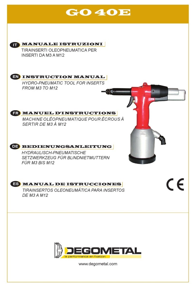
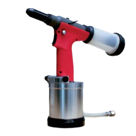
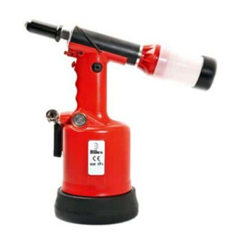
Degometal GO 61 Manual

Pour Ecrous à sertir/Inserts
M3 à M10 Alu, Acier, Inox
For Rivet nuts
M3 to M10 Alu, Steel, Stainless Steel
GO 61
CONSIGNES DE SÉCURITÉ ET MODE D'EMPLOI
SAFETY INSTRUCTIONS AND DIRECTIONS FOR USE

2
www.degometal.com

3
www.degometal.com
1. GO 61 : PRÉSENTATION............................................................................................... 5
2. ARRIVÉE D’AIR ............................................................................................................ 6
3. PRÉPARATION............................................................................................................. 7
4. OPÉRATION ................................................................................................................ 8
5. CHANGEMENT DES NEZ .............................................................................................. 9
6. MISE EN SERVICE...................................................................................................... 10
7. AJOUT D’HUILE......................................................................................................... 10
8. VUE ÉCLATÉE ............................................................................................................ 11
9. GARANTIE & CERTIFICATION CE ................................................................................ 13
1. GO 61 : PRESENTATION............................................................................................. 15
2. AIR SUPPLY............................................................................................................... 16
3. PREPARATION........................................................................................................... 17
4. OPERATION .............................................................................................................. 18
5. CHANGING NOSE ASSEMBLIES .................................................................................. 19
6. PUTTING INTO SERVICES........................................................................................... 20
7. ADDING OIL.............................................................................................................. 20
8. EXPLODED DRAWING ............................................................................................... 21
9. WARRANTY & CE CERTIFICATION .............................................................................. 23

4
www.degometal.com

5
www.degometal.com
1. GO 61 : PRÉSENTATION
●Capacité : Écrous à sertir de M3 à M10
Outil fourni avec des tirants de M3 à M10.
●L’huile doit être appliquée correctement pour prolonger
la durée de vie et améliorer l’efficacité du sertissage.
●Poussez légèrement l’écrou au bout du tirant ; l’écrou
se visse sur le tirant automatiquement.
●Cycle de sertissage en 2 étapes :
- Sertissage
- Dévissage.
●Maintenance et fonctionnement faciles. Nous
recommandons un entretien après chaque cycle de
6 000 sertissages.
L’outil est fourni avec les accessoires standards :
●Un jeu de nez avec écrou de réglage
●Tirant, douille réductrice.
●Arbre d’entraînement de M3 à M10.
●Goupille de régulation de course
Code
Article
Force de
Traction
Course Pression
d’utilisation
Capacité Poids
100 000 611
18.3 KN
0-7mm
5-7 bars
M3 à M10
1.92 Kg
FRANCAIS
ENGLISH

6
www.degometal.com
2. ARRIVÉE D’AIR
●L’outil fonctionne avec de l’air comprimé entre 3-7KGF/CM2 (45-105PSI). Nous
recommandons l’utilisation de régulateurs et de systèmes de lubrification/filtration
automatiques sur l'alimentation en air. Ceux-ci doivent être installés à moins de 3
mètres de l’outil pourgarantir une duréede vie maximale et une maintenance minimale.
●Les tuyaux d’alimentation en air utilisés doivent avoir une résistance à la
pression adaptée. Les tuyaux d’air doivent être résistants à l’huile, avoir un extérieur
résistant à l’abrasion et doivent être blindés là où les conditions de fonctionnement
peuvent endommager les tuyaux. Tous les tuyaux d’air DOIVENT avoir un diamètre
d’alésage minimum de 6,4 mm ou ¼ de pouce.
●Un filtre à air est nécessaire pour éliminer les contaminants et l’humidité
contenus dans l’air comprimé, car l’outil pourrait ne pas fonctionner à cause du moteur
rouillé et de corps étrangers introduits dans l’air comprimé.

7
www.degometal.com
3. PRÉPARATION
Ajustement du tirant
Ajustez le tirant avant de l’utiliser ; une fois l’écrou mis en
place,letirantdoitlégèrementdépasserdel’écrou(environ
1mm) (voir Fig.1).
Si le tirant dépasse trop oupas assez, ajustezle contre-écrou danslaposition optimale
et bloquez bien le contre-écrou sur le nez de pose de l’outil.
Réglage de la course
Ce réglage est nécessaire pour assurer une déformation
optimale de l’écrou. Si la course est trop importante, la
déformation de l’écrousera trop importante (possibilité que
l’écrou reste bloqué sur le tirant, ou que le tirant casse).
Alors que si la course est trop courte, la déformation de
l’écrou sera insuffisante et l’écrou ne sera pas fixé
correctement.
Ajustez la course pour obtenir le serrage optimal. Assurez-vous que l’outil soit ajusté
par un technicien ou un personnel formé pour la première utilisation.
1) Il est recommandé d’utiliser une plaque d’essai avec la même épaisseur, le même
matériau et le même diamètre de perçage que la pièce finale pour le réglage.
2) Commencez le réglage de la course avec la course la plus petite et augmentez petit
à petit. Tourner l’écrou de réglage vers le + jusqu’à obtenir le serrage/déformation
optimal(e).
Remarque : Ne jamais re-sertir un écrou qui aurait été insuffisamment serti ! Modifiez
la course et re-sertir un autre écrou pour voir le résultat.
FRANCAIS
ENGLISH
Fig. 2
Fig. 1
Le tirant doit
légèrement dépasser
de l’écrou

8
www.degometal.com
4. OPÉRATION
Action
Ⅰ
– Vissage de l’écrou sur le tirant
Vissez l’écrou sur le tirant automatiquement sans
appuyer sur la gâchette.
Action
Ⅱ
– Sertissage / pose de l’écrou
Appuyez sur la gâchette pour aller en position A (appui léger).
Action
Ⅲ
– Dévissage
Appuyez sur la gâchette à fond pour passer de la position A à la
position B.
Remarque : Cycle de sertissage en 2 étapes (A et B) : étape A pour sertir l’écrou,
étape B pour dévisser le tirant.
Vissage et réglage de l’écrou à sertir sur le tirant (deux options) :
1) Poussez directement l’écrou contre le tirant à la main avec une légère pression,
l’écrou se visse automatiquement sur le tirant (Voir fig. ci-dessus à gauche).
2) Mettez d’abord l’écrou à sertir dans l’application, déplacez le tirant dans l’écrou.
(Voir Fig. En haut à droite).

9
www.degometal.com
5. CHANGEMENT DES NEZ
Les pièces de rechanges entourées d’un “○” doivent être changées à chaque fois que
l’on veut passer sur un autre diamètre.
Veuillez suivre le processus suivant :
1) Déconnectez l’outil de l’alimentation en air comprimé.
2) Placez la clé sur le contre-écrou (article 2), dévissez l’écrou et le contre-écrou
(article 1et 2) dans le sens inverse des aiguilles d’une montre.
3) Dévissez le nez de pose de l’outil (article 3) avec la clé.
4) Bloquez la broche avec la clé de 12 (article 9) et dévissez l’écrou adaptateur
(article 4) à l’aide de la clé 17.
5) Changez l’écrou d’entraînement (article 7), le tirant (article 6), la bague de
maintien (article 5) en conséquence.
6) Serrez la broche (article 9) et l’écrou adaptateur
7) Vissez le nez de pose (article 3), changez et régler l’écrou et le contre-écrou
(articles 1 et 2) en fonction de la longueur de l’insert, puis bloquer le contre-écrou
sur le nez de pose de l’outil.
Attention : L’alimentation en air doit être déconnectée lors du
changement de nez.
FRANCAIS
ENGLISH
Vue éclatée

10
www.degometal.com
6. MISE EN SERVICE
Maintenance de la panne
Si l’écrou à sertir est bloqué sur le tirant et qu’il ne peut pas
se dévisser : Veuillez déconnecter l’outil de l’alimentationen
air, mettre la goupille de réglage de la course dans le trou
droit de la broche et dévisser l’écrou avec la main.
7. AJOUT D’HUILE
Après une longue période et un fonctionnement continu, la déformation de l’écrou peut
ne pas être suffisante avec une course maximale = > De l’huile doit alors être ajoutée.
Déconnectez l’outil de l’alimentation en air :
1) Maintenez l’outil dans une position stable pendant toute l’opération. Dévissez la vis
du joint (article 15) et le joint (article 14) avec une clé Allen de 4 mm.
2) Remplissez la seringue (incluse) avec de l’huile hydraulique. Vissez la seringue
remplie jusqu’au trou, puis injectez lentement l’huile dans l’outil. La quantité d’huile
adéquate a été ajoutée dès qu’une résistance est détectée ; l’excès d’huile refluera
lorsque vous relâcher la seringue.
3) Dévisser et retirer la seringue du corps, remettre le joint et visser la vis au joint.
4) Essuyez l’excès d’huile
Avertissement : Si vous renversez accidentellement de l’huile sur votre peau,
lavez et rincez abondamment avec de l’eau et du savon alcalin.

11
www.degometal.com
8. VUE ÉCLATÉE
FRANCAIS
ENGLISH

12
www.degometal.com
GO 61 : Pièces Détachées
N° ITEM DESCRIPTION QTY N° ITEM DESCRIPTION QTY
1Z00610001M3 EMBOUT DIAM. M3 132 Z00610032 BILLE 1
1Z00610001M4 EMBOUT DIAM. M4 134 Z00610034 JOINT TORIQUE 1
1Z00610001M5 EMBOUT DIAM. M5 135 Z00610035 VIS À RESSORT 1
1Z00610001M6 EMBOUT DIAM. M6 136 Z00610036 ANNEAU DE SERRAGE B 2
1Z00610001M8 EMBOUT DIAM. M8 137 Z00610037 TUBE D'AIR 2
1Z00610001M10 EMBOUT DIAM. M10 138 Z00610038 VIS D'ARRÊT M3 4
2Z00610002 CONTRE-ÉCROU 139 Z00610039 VIS D'ARRÊT M5 4
3Z00610003M3 TIRANT DIAM. M3 140 Z00610040 BOUCHON INVERSEUR 1
3Z00610003M4 TIRANT DIAM. M4 141 Z00610041 JOINT TORIQUE 2
3Z00610003M5 TIRANT DIAM. M5 142 Z00610042 JOINT TORIQUE 3
3Z00610003M6 TIRANT DIAM. M6 143 Z00610043 BAGUE EN FIBRE DE CARBONE 3
3Z00610003M8 TIRANT DIAM. M8 144 Z00610044 VANNE D'INVERSION 1
3Z00610003M10 TIRANT DIAM. M10 145 Z00610045 TIGE DE SOUPAPE INVERSE 1
3A Z00610003M3A TIRANT DIAM. M3 146 Z00610046 ECROU DE VANNE INVERSE 1
3A Z00610003M4A TIRANT DIAM. M4 147 Z00610047 GACHETTE 1
3A Z00610003M5A TIRANT DIAM. M5 148 Z00610048 GOUPILLE DE DÉCLENCHEMENT 1
3A Z00610003M6A TIRANT DIAM. M6 149 Z00610049 JOINT TORIQUE 2
3A Z00610003M8A TIRANT DIAM. M8 150 Z00610050 MANCHON HYDRAULIQUE 1
3A Z00610003M10A TIRANT DIAM. M10 153 Z00610053 CYLINDRE D'AIR 1
4Z00610004M3 REDUCTEUR HEXAGONAL M3 154 Z00610054 CONTRE-ÉCROU 1
4Z00610004M4 REDUCTEUR HEXAGONAL M4 155 Z00610055 COLLECTEUR TUBE D'AIR M6 4
4Z00610004M5 REDUCTEUR HEXAGONAL M5 156 Z00610056 TUBE D'AIR 2
4Z00610004M6 REDUCTEUR HEXAGONAL M6 157 Z00610057 TUBE DE MOUVEMENTD'AIR 1
4Z00610004M8 REDUCTEUR HEXAGONAL M8 159 Z00610059 TIGE DE PISTON PNEUMATIQUE 1
4Z00610004M10 REDUCTEUR HEXAGONAL M10 161 Z00610061 JOINT TORIQUE 1
5Z00610005M3 ENTRETOISE M3 162 Z00610062 PISTON PNEUMATIQUE 1
5Z00610005M4 ENTRETOISE M4 163 Z00610063 VIS HEXAGONALE 1
5Z00610005M5 ENTRETOISE M5 164 Z00610064 BAGUE D'ÉTANCHÉITÉ 1
5Z00610005M6 ENTRETOISE M6 166 Z00610066 BASE EN CAOUTCHOUC 1
5Z00610005M8 ENTRETOISE M8 170 Z00610070 VIS M4 2
5Z00610005M10 ENTRETOISE M10 171 Z00610071 POIGNÉE DROITE EN NYLON 1
6Z00610006 JOINT TORIQUE 172 Z00610072 POIGNÉE GAUCHE EN NYLON 1
7Z00610007 CONE EXTERNE 173 Z00610073 VIS 4
8Z00610008 CÔNE PORTE TIRANT M3 à M10 274 Z00610074 COUVERCLE MOTEUR 1
9Z00610009 TUBE PORTE TIRANT 175 Z00610075 VIS FEMELLE 2
9A Z00610009A TUBE PORTE TIRANT 176 Z00610076 RACCORD D'AIR 1
9A1 Z00610009A1 RESSORT 177 Z00610077 JOINT TORIQUE 1
9A2 Z00610009A2 GOUPILLE 178 Z00610078 PLATINE 1
9A3 Z00610009A3 CONNECTEUR HEXAGONAL 180 Z00610080 JOINTBALSEL 1
10 Z00610010 CONTRE-ÉCROU 181 Z00610081 TUBE HYDRAULIQUE 1
11 Z00610011 VIS DU CYLINDRE HYDRAULIQUE 182 Z00610082 JOINT TORIQUE 1
12 Z00610012 JOINT BALSEL 183 Z00610083 SEGMENTPISTON PNEUMATIQUE 1
13 Z00610013 CYLINDRE SUPERIEUR 184 Z00610084 RONDELLE DE PISTON PNEUMATIQUE 1
14 Z00610014 RONDELLE HERMETIQUE 185 Z00610085 CIRCLIP 1
15 Z00610015 VIS DE PURGE 186 Z00610086
RONDELLE DE CYLINDRE HYDRAULIQU
1
16 Z00610016 CROCHET 187 Z00610087 CORPS INFERIEUR 1
17 Z00610017 JOINT TORIQUE 488 Z00610088 CIRCLIP DE MOTEUR 1
18 Z00610018 BAGUE DE SERRAGE A 289 Z00610089 ROULEMENT DE MOTEUR 1
19 Z00610019 VIS 190 Z00610090 BROCHE D'ENGRENAGE DE MOTEUR 1
20 Z00610020 JOINT BALSEL 191 Z00610091 PLANÈTE DU MOTEUR 3
21 Z00610021 PISTON HYDRAULIQUE 492 Z00610092 ENGRENAGE DU MOTEUR 1
22 Z00610022 RESSORT 193 Z00610093 ENTRETOISE DE MOTEUR 1
23 Z00610023
BOUCHON DE REGLAGE DE COUR
194 Z00610094 ROULEMENT DE MOTEUR 1
24 Z006100024 RONDELLE 195 Z00610095 PLAQUE AVANTDU MOTEUR 1
25 Z006100025 PIVOT ROTATION 196 Z00610096 STATOR DE MOTEUR 1
26 Z006100026 CONNECTEUR DE MOUVEMENT 197 Z00610097 ROTOR DE MOTEUR 1
27 Z006100027 GOUPILLE ÉLASTIQUE 198 Z00610098 ROTOR PALETTE DE MOTEUR 5
29 Z00610029 KIT MOTEUR 199 Z00610099 PLAQUE DE FIN DU MOTEUR 1
30 Z00610030 CARTER MOTEUR 1100 Z00610100 ROULEMENT DU MOTEUR 1
31 Z00610031 TIGE DE POUSSOIR 1101 Z00610101 GOUPILLE 1
KIT MOTEUR REF 29

13
www.degometal.com
9. GARANTIE & CERTIFICATION CE
GARANTIE
Les outils endommagés suite à une mauvaise utilisation ne pourront pas être pris sous
garantie.
La garantie est de 12 mois à compter de la date de facturation. En cas de problème,
retourner l’outil et ses accessoires dans son emballage d’origine.
Pour toute question, adressez-vous à votre distributeur ou bien à Degometal via le site
internet www.degometal.com
CERTIFICATION CE
EC Déclaration de Conformité
Nous déclarons par la présente, que cet outil, lorsqu’il est utilisé et entretenu
conformément aux codes de bonne pratique généralement acceptés et aux
recommandations du manuel d'instructions, répondent aux exigences essentielles de
sécurité et de santé de la directive Machines 2006/42/CE.
Pour lesrisques lesplus spécifiquesde cet outil, la sécurité et le respect desexigences
essentielles de la directive ont été sur la base d'éléments de :
• EN ISO 12100:2010/ Sécurité des machines - Principes généraux de conception -
Évaluation et réduction des risques-
• EN ISO 11148-1:2011/ Outils portatifs non électriques
Carros, Octobre 2021 Corinne JOUX
P.D.G.
FRANCAIS
ENGLISH

14
www.degometal.com

15
www.degometal.com
1. GO 61 : PRESENTATION
●Capacity: Blind rivet nuts from M3 to M10
Tool supplied with mandrels from M3 to M10 in metric.
Mandrels in inch are available to purchase.
●Oil should be applied properly to extend the life and
improve the work efficiency.
●Push the insert nut lightly on the end of themandrel, the
insert nut will screw onto the mandrel and stop
automatically.
●Trigger by two action design (Action A and Action B), A
for fastening, B for reversing, improve the stability of the
tool.
●Easy maintenance and operation, up to 6,000 pcs of
threaded insert per shift.
The tool is supplied with thestandard accessories:
●One set of nose piece with set nut,
●Drive shaft from M3 to M10,
●Stroke regulation pin.
Item No.
Pull Force
Stroke
Air Pressure
Capacity
Weight
100 000 611 18.3 KN 0-7mm 5-7 bars
M3 to M10
1.92Kg
FRANCAIS
ENGLISH

16
www.degometal.com
2. AIR SUPPLY
●The tool is operated with compressed air between 3-7KGF/CM2 (45-105PSI). We
recommendtheuseofpressureregulatorsandautomaticoiling/filteringsystemson
the main air supply. These should be fitted within 3 meters of the tool to ensure
maximum tool life and minimum tool maintenance.
●The air supply pipes used must have a suitable pressure resistance. Air hoses
should be oil resistant,have an abrasion resistant exterior and should be armoured
where operating conditionsmay result in hoses beingdamaged.All air hoses MUST
have a minimum bore diameter of 6.4mm or 1/4 inch.
●An air filter is needed to remove contaminates and moisture that are contained in
compressed air, or the tool might not work well caused the rusty motor and foreign
materials in the compressed air.

17
www.degometal.com
3. PREPARATION
Mandrel Protrusion Adjustment
Adjust the mandrel protrusion before operating. Take the
mandrel protrudes by one thread from the back of the nut
asstandard(see Fig.1).Ifthemandrel protrudes too long or
too short, adjust the nose piece to the optimum position
and lockthe set nut well.
Stroke Adjustment
This adjustment is necessary to ensure optimum insert
deformation. If the stroke is too long, the insert nut thread
distortion will occur and possibly the screw mandrel sticks
inside theinsert nut, even screw mandrel fracture. While if
the stroke is too short, the deformation is insufficient, the
insert nut will rotate inside the application.
Adjust the exact stroke to meet the optimum pull force. Make sure the toolwill be
adjusted by technician or trained personnel for the first time use.
1) It is suggested that a test plate with the same thickness, material and hole size as
workpiece be used for the adjustment.
2)Take “from short to long” as the standard for adjusting the stroke, the tool is
supplied as standard with fitted M6 insert nut. If M3, M4, M5 insert nut is required,
turn the ring nuttowardsthe“-”markwith the stroke regulationpinto shortenstroke
to optimum. If M8, M10 insert nut is required, turn the ring nut towards the “+” mark
with the stroke regulation pin to lengthen stroke to optimum.
Notice: Re-setting the insert nut is prohibited for the insufficientdeformation.
Fig. 2
Fig. 1
one thread extruded
from the rivet nut
FRANCAIS
ENGLISH

18
www.degometal.com
4. OPERATION
Mandrel Protrusion Adjustment
Action
Ⅰ
Insert nut screws onto the mandrel automatically without
pulling the trigger.
Action
Ⅱ
Pull the rigger lightly, getting position A, the insert nut
deformed.
Action
Ⅲ
Keep pulling the trigger toward Position B, the screw
mandrel reversed off the application.
Note: Trigger by two action design (Action A and Action B), Action A for fastening
theinsert nut with light force, Action B for reversing the screw mandrel, you will
get harder when do action B.
Screwing and setting the insert nut onto the screw mandrel:
1) Offer up insert nut, push straight against the screw mandrel with hand with light
pressure, the insert nut will screw onto screw mandrel automatically. (See Fig.
Above left one).
2) Putthe insertnut into the applicationfirst,movesthe screw mandrelinto the insert
nut squarely. (See Fig. Above right one).

19
www.degometal.com
5. CHANGING NOSE ASSEMBLIES
Spare parts number circled with“○” shall be changed completely, if the size of insert
nut changed.
Please take the process as follows:
1) Disconnect the tool from the compressed air supply.
2) Set the spanner onto lock nut (Item 2), unscrew the nose piece (Item 1)counter
clockwise.
3) Unscrew the nose casing off with the spanner.
4) Set the spindle (Item 9) with the spanner, unscrew and remove the adaptor nut
(Item 4)
5) Change the drive shaft (Item 7), mandrel (Item 6), reducing sleeve (Item 5)
accordingly.
6) Tighten the spindle (Item 9) and the adaptor nut (Item 4) clockwise with a spanner.
7) Screw on the nose casing (Item 3), change and set the nose piece (Item 1) in
exact pistion according to the right mandrel protrusion, then lock nose piece lock
nut with spanner.
Warning: The air supply must be disconnected when changing nose
assemblies.
FRANCAIS
ENGLISH

20
www.degometal.com
6. PUTTING INTO SERVICES
Breakdown Maintenance
If the insert nut blocked on the mandrel, and it cannot screw
off from the mandrel by the motor.Pleasedisconnectthetool
from the air supply, andput the stroke regulation pin into the
right hole of the spindle and unscrew the nut off with hand.
7. ADDING OIL
After long time and continuous operation, the insert nut deformation might be not
sufficient with maximum stroke, then oil shall be addedas follows:
1) Disconnect the tool from the air supply.
2) Keep the tool upright in stable position during all operations. Unscrew the seal
screw (Item 15) and the seal (Item 14) with 4mm Allen key.
3) Fill the syringe (included) with hydraulic oil, screw the filled syringe up to the hole,
then slowly inject the oil into the tool, adequate oil has been added as soon as
resistance is sensed, the excess oil will flow back when you release the syringe.
4) Unscrew and remove the syringe from the body, put the seal back and screw the
seal screw tight.
5) Wipe off the excess oil.
Warning: If you should accidentally spill oil on your skin, washand rinse
thoroughly with water and alkaline soap.
Table of contents
Languages:
Other Degometal Power Tools manuals
Popular Power Tools manuals by other brands

Porter-Cable
Porter-Cable PCE345-CA instruction manual
ALAT UJI
ALAT UJI DTW Series operating instructions

Ronix
Ronix 3401 instruction manual
Cornwell Tools
Cornwell Tools CAT-250AR Operating instructions, warning information, parts breakdown
Campbell Hausfeld
Campbell Hausfeld SN528K operating instructions
Precision matthews
Precision matthews PM-932M manual
