Rockler ProMax Fence User manual

Review full instructions prior to use for important safety information.
Always check Rockler.com to confirm that you are using the most recent version of instructions for your product.
ProMax Fence Instructions
Effective June 2020

2BP1219
GENERAL SAFETY WARNINGS
This product is designed only for specific applications as defined in the instructions and should not be modified or used for
any manner not described in these instructions. Use only recommended accessories. Before using the ProMax Fence: READ,
UNDERSTAND and FOLLOW ALL INSTRUCTIONS AND SAFETY WARNINGS. KEEP THESE INSTRUCTIONS READILY
AVAILABLE FOR FUTURE REFERENCE.
>Always confirm that you are using the most recent version of
the Instructions and safety warnings for your product (see the
Instructions link on the product page at Rockler.com).
>Before using another tool with this product, always read,
understand and follow the instructions and safety warnings
in the owner’s manual for that tool. If you do not have the
owner’s manual, obtain one from the tool’s manufacturer
before using it with this product.
>Before using any chemical with this product, always read,
understand and follow all safety warnings and guidelines in
the manufacturer’s Safety Data Sheet (SDS; formerly called
“MSDS”), especially regarding:
• How to safely use the chemical, including potential hazards
and recommended first aid measures;
• Personal safety equipment required to safely use the
chemical (e.g. gloves, eye protection, mask/respirator, etc.);
• Proper and safe handling, storage and disposal of
the chemical.
>Before using this product, review and verify that all tools to be
used with it have safety equipment installed and are in proper
working order as defined by the tool’s owner’s manual.
>Do not use this product until you have read and are
confident you understand:
• Product Specific Safety Warnings (p. 3);
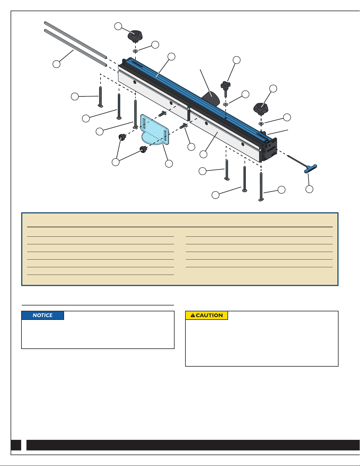
• Parts List (p. 4);
• Assembly (p. 4);
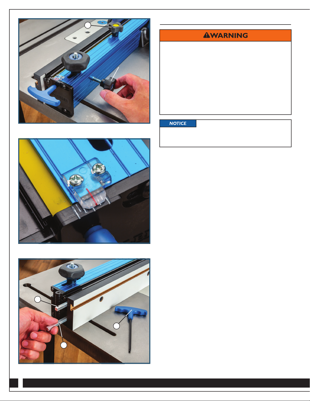
• Adjusting the MDF Fence Faces (p. 5);
• Using the Micro-Adjust Function (p. 6);
• Using the Jointer Bars (p. 7).
>The user assumes all risk and responsibility for the proper and
safe use of this product and for ensuring product suitability for
the intended application.
>It is the sole responsibility of the purchaser of this product to
ensure that any anyone you allow to use this product reads
and complies with all instructions and safety precautions
outlined in this manual prior to use.
>Follow all standard shop safety practices, including:
• Keep children and bystanders away from the tool
operating area;
• Do NOT use power tools in explosive environments, or in
the presence of flammable liquids, fumes or dust;
• TURN OFF AND UNPLUG all power tools BEFORE
making any adjustments or changing accessories;
• Remain alert and use good judgment. Do not use this
product if you are in any way impaired by medications,
alcohol, drugs or fatigue;
• Keep your work area well lit and clean;
• Dress appropriately. Secure loose clothing, remove all
jewelry and tie up long hair before using this product;
• ALWAYS wear safety glasses, hearing protection
and respiratory protection that complies with
NIOSH/OSHA/ANSI safety standards;
• Use dust collection tools and dust face masks to
reduce exposure to dust;
• Use safety equipment such as featherboards, push
sticks and push blocks, etc., when appropriate;
• Maintain proper footing at all times and do not overreach;
• Do NOT force woodworking tools.
>These warnings and instructions do NOT represent the total
of all information available regarding tool safety, use and
technique. Always seek out opportunities to learn more
and improve your skills and knowledge.
Drilling, sawing, sanding or machining wood
products can expose you to wood dust, a substance known
to the State of California to cause cancer. Avoid inhaling
wood dust or use a dust mask or other safeguards for
personal protection. For more information go to
www.P65Warnings.ca.gov/wood.
Danger indicates a hazardous situation that, if not avoided, will result in death or serious injury.
Warning indicates a hazardous situation that, if not avoided, could result in death or serious injury.
Caution indicates a hazardous situation that, if not avoided, may result in minor or moderate injury
or property damage.
Notice indicates important or helpful information and/or user tips.

3
PRODUCT SPECIFIC SAFETY WARNINGS
>To avoid serious injury, keep hands and fingers away from the spinning router bit.
Maintain awareness of the bit at all times.
> Set the Bit Safety Guard (3) directly over the router bit,
at least 1/2" above the top of the bit or the top of the
workpiece (whichever is highest) to make sure that
the bit doesn’t cut into the Bit Safety Guard.
>When adjusting the position of the ProMax Fence, make
sure that no part of the aluminum body will contact the
router bit.
>If using the Jointer Bars (11), always use them in
pairs. Failure to install both Jointer Bars is likely to
yield poor results.
> Turn off and unplug your router before installing or adjusting
the bit or adjusting the ProMax Fence.
>BEFORE beginning any routing operation, ALWAYS make
sure that ALL knobs on the ProMax Fence — including the
Fence Locking Knob —have been tightened and the fence
will not shift during use.
>Always feed the workpiece against the rotation of the bit.
A table-mounted router spins the bit counterclockwise, so
feed the workpiece from right to left as you face the table.
This provides better control because the rotation of the
bit is backward and toward the fence instead of forward
and away from it.
>NEVER attempt to machine a workpiece at the router
table without using the ProMax Fence or a starter pin with
a bearing-guided bit. Failure to use these guides diminishes
your ability to control the workpiece and greatly increases
the chance of damage to the workpiece and/or serious
personal injury.
>BEFORE plugging in and turning on the router, always
check to be sure that the MDF Adjustable Fence Faces (2)
are fully secured and that the bit can rotate freely without
touching the Fence Faces. An exception to this is if
you have set up the infeed Fence Face to provide
zero-clearance support for the workpiece, as described
in the “Adjusting the Fence Faces” section on Page 5.
>Do NOT attempt to use the ProMax Fence to joint board
edges that are thicker than 11⁄4". The maximum material
thickness might be further limited by the cutting height of
the router bit being used. For example, a bit with
a 3/4" cutting height will be able to joint only boards that
are 3/4" thick or less.
>When working with narrow boards, use a push block
or push stick to advance the workpiece to avoid fingers
from contacting the bit and causing serious injury.
>Use only 1/2" shank router bits for jointing. The thicker
shank will provide less chatter and cleaner cuts. The
bit’s cutting height must not exceed 11⁄2".
>Never use a router bit that is damaged or dull.
>Never exceed the manufacturer’s recommended maximum
operating speed for your router bit.
> NEVER FEED YOUR WORKPIECE BETWEEN THE
BIT AND THE FENCE. Because of the direction of the
bit’s rotation, the bit could “grab” the workpiece and
propel it away from the table at a high velocity, potentially
resulting in property damage and serious injury to
anyone in its path.
>Additionally, when the bit grabs the workpiece,
your hands could be drawn into the bit, resulting
in serious injury.
AVOID THIS SITUATION!
Fence
Workpiece
Bit Rotation Feed
Direction

4
Assembly
1. Slide a 5/16"-18 x 1" T-Bolt (4) into the forward-facing T-Slot
of each MDF Adjustable Fence Face (2). Fit the Bit Safety
Guard (3) over the T-Bolts and secure with a 1" Round
Knob (8) on each T-Bolt.
2. Insert the appropriate 5/16"-18 Bolts for your router
tabletop (5, 6 or 7) into the slots in the bottom of the
Fence Body (1) and out the slots in the top. Then fit a
5/16" Nylon Washer (10) and loosely thread a 5/16"-18
Five-Star Knob (9) on each.
3. Fit the bottoms of the appropriate 5/16"-18 Bolts (5, 6 or 7)
into the mounting slots in your router table.
Quantity
1 Fence Body 1
2MDF Adjustable Fence Face 2
3Bit Safety Guard 1
45/16"-18 x 1" T-Bolt 2
55/16"-18 x 5" T-Bolt 2
65/16"-18 x 41⁄2" Carriage Bolt 2
75/16"-18 x 31⁄2" T-Bolt 2
PARTS LIST Quantity
85/16"-18 1" Round Knob 2
95/16"-18 Five-Star Knob 2
10 5/16" Nylon Washer 3
11 Jointer Bar 2
12 Hex Key 1
13 Fence-Locking Knob 1
Three different types of bolts are included
for mounting the ProMax Fence to any of Rockler’s router
tabletops: 5/16"-18 x 5" T-Bolts; 5/16"-18 x 31⁄2" T-Bolts; and
5/16"-18 x 41⁄2" Carriage Bolts. Use the bolts that work with
your tabletop.
Set the Bit Safety Guard (3) directly over
the router bit, at least 1/2" above the top of the bit or the top
of the workpiece (whichever is highest) to make sure that
the bit doesn’t cut into the Bit Safety Guard.
When adjusting the position of the ProMax Fence, make
sure that no part of the aluminum body will contact the
router bit.
4. Slide the ProMax Fence to the desired position and tighten
the 5/16"-18 Five-Star Knobs (9) to lock it in position.
5. Fit a 5/16" Nylon Washer (10) onto the post of the
Fence-Locking Knob (13) and then thread the post
into the hole in the top of the fence.
21⁄4" ID / 21⁄2" OD
Dust Port
Micro-Adjust Knob
11
7
6
5
83
4
7
6
512
10
9
13
10
1
10
9
2

5
Infeed Fence Face Adjusted to Provide Zero-Clearance Support
Set the Bit Safety Guard (3) directly over
the router bit, at least 1/2" above the top of the bit or the top
of the workpiece (whichever is highest) to make sure that
the bit doesn’t cut into the Bit Safety Guard.
When adjusting the position of the Router Table Fence,
always ensure that no part of the Aluminum Fence (1) will
contact the router bit.
Outfeed subfence Infeed subfence
Router bit guide bushing
Router Bit
Feed Direction
>To avoid serious injury, keep hands
and fingers away from rotating cutter.
Maintain awareness of the cutter
at all times.
Turn off and unplug your router before
installing or adjusting the bit or adjusting the Router
Table Fence.
Never use a router bit that is damaged or dull.
Never exceed the manufacturer’s recommended maximum
operating speed for your router bit.
Adjusting the MDF Fence Faces
The two MDF Adjustable Fence Faces (2) are designed to slide
about 2" along the fence. As a result, the opening for the router bit
can be adjusted from 0" up to 33⁄4". Generally, you want to set the
Adjustable Fence Faces (2) as close to the bit as possible (without
contacting the cutter) to provide support for your workpiece
during the cut. Setting both infeed and outfeed Adjustable Fence
Faces close to the bit helps prevent the ends of the workpiece
from drifting too far into the cutter at the beginning and end of
the cut, providing enhanced safety and cut quality.
In some cases, you might want “zero-clearance” support to deliver
an even cleaner cut. This involves cutting the router bit profile
into the front edge of the infeed Adjustable Fence Face so that
there’s virtually no gap between the cutter and the Fence Face.
It delivers a cleaner cut because the workpiece fibers are fully
supported throughout the cut.
If a zero-clearance setting is necessary, follow these steps:
1. Use the blue-handled Hex Key (12) to slightly loosen the
flat-head hex screws that secure the MDF Adjustable Fence
Faces to the Fence Body (1). (Don’t loosen them too far,
however, or they could disengage from the weld nuts that
snug them to the Fence Body.) Slide the MDF Adjustable
Fence Faces outward enough that they won’t contact the
bit when the fence is moved into position.
2. Set the bit height and use a straightedge to position the fence
so that the faces of the MDF Adjustable Fence Faces (2) are
flush with the router bit’s guide bearing. Set both Fence Faces
close to the bit, but not touching it, and tighten the flat-head
hex screws on the outfeed Fence Face. The Fence Faces
MUST NOT contact the bit at this time.
3. Install and secure the Bit Safety Guard (3).
4. Start the router and slowly slide the infeed MDF Adjustable
Fence Face (2) into the spinning router bit, stopping when
the edge reaches the bit’s guide bearing or midpoint (for bits
that don’t have a guide bearing).
5. Turn off the router. Fully tighten the flat-head hex screws
on the infeed MDF Adjustable Fence Face (2) to secure
it in position.

6
Using the Micro-Adjust Function
The ProMax Fence’s two-part pivot design and micro-adjust
function allow the MDF Adjustable Fence Faces (2) to be fine-
tuned forward (or back) without having to move the rest of the
fence. Whether the movement is forward or back depends on how
you initially set the Micro-Adjust Knob on the fence.
For example, if you are routing an edge profile on a board that’s
prone to router burn, you might want to do it in several lighter
passes, moving the fence face backward a bit with each pass. In
this application, you would start with the fence adjusted out.
If you want to make it easier to align the fence face with the
guide bearing on a router bit, you might start with the fence face
adjusted back as far as it will go and set the fence close to but a
little back from the edge of the guide bearing. Then you can turn
the Micro-Adjust Knob to move the fence out until it’s perfectly
flush.
To use the micro-adjust function:
1. Loosen the Fence-Locking Knob (13) on the top of the fence.
Fig. 1.
2. Slightly turn the Micro-Adjust Knob on the back of the fence
to move the fence face forward or back, as desired. You can
track the adjustment using the clear indicator and scale on
the end of the ProMax Fence. Yellow tape on the top of the
black part of the fence also will become visible as you adjust
the fence face outward. Note that the middle of the fence
(where the bit is located) will move about half the distance
shown with the the indicator lines. We recommend that you
make small adjustments to sneak up on the right setting.
Fig. 2.
3. Tighten the Fence-Locking Knob (13) on the top of the fence
to secure the fence face in position.
4. Make another test cut to verify that the setting is correct.
5. Repeat Steps 1-3 until you achieve the desired results.
Fig. 2
Fig. 1
Fig. 3
> BEFORE beginning any routing operation, ALWAYS
make sure that ALL knobs on the ProMax Fence —
including the Fence Locking Knob — have been
tightened and the fence will not shift during use.
> BEFORE plugging in and turning on the router, always
check to be sure that the MDF Adjustable Fence
Faces (2) are fully secured and that the bit can rotate
freely without touching the Fence Faces. An exception
to this is if you have set up the infeed Fence Face to
provide zero-clearance support for the workpiece, as
described in the “Adjusting the MDF Fence Faces”
section on Page 5.
As with most jigs, we recommend making
test cuts with offcuts or scrap pieces matching the thickness
of your final workpieces to achieve the proper setup before
machining your final workpieces.
Micro-Adjust Knob
13
11
11
12

7
Using the Jointer Bars
Jointing is the process of cutting flat, square, straight edges on
a board. It’s typically done on a free-standing power jointer but
can be done on a router table for boards that are no thicker than
the cutting height of the router bit used. The ProMax Fence has
integral slots to accept the included aluminum Jointer Bars (11).
When installed in pairs in the slots, these bars “shim out” the
outfeed Fence Face by 1/32".
1. Unplug the router and install a straight or spiral up-cut router
bit, setting the cutting height according to the capacity of the
bit and the thickness of your stock.
2. Use the blue-handled Hex Key (12) to slightly loosen the
flat-head hex screws securing the outfeed MDF Adjustable
Fence Face (2) to the Fence Body (1). (Don’t loosen them
too far, however, or they could disengage from the weld
nuts that snug them to the Fence Body.)
3. Slide both Jointer Bars (11) out from the slots behind the
outfeed MDF Adjustable Fence Face (2) and turn them 90°.
Then slide them back into the slots. This will push the
outfeed MDF Adjustable Fence Face out by 1/32". Fig. 3.
4. Use the blue-handled Hex Key (12) to tighten the flat-head
hex screws securing the outfeed MDF Adjustable Fence
Face (2) to the Fence Body (1).
5. Set the fence position so that the plane of the outfeed MDF
Adjustable Fence Face (2) is just slightly behind the front
edge of the bit.
6. Using a straightedge held flush against the outfeed
MDF Adjustable Fence Face (2) as a guide, loosen the
Fence-Locking Knob on the top of the fence and turn the
Micro-Adjust Knob on the back of the fence to align the
outfeed side precisely with the cutting edge of the bit.
7. Remove the straightedge. If necessary, adjust the MDF
Adjustable Fence Faces (2) to make the gap between the faces
and the bit as small as possible without making contact with
the bit. Adjust the Bit Safety Guard (3).
8. Plug in the router and make a test cut in scrap stock. If
adjustments are needed, unplug the router and use the
ProMax Fence’s micro-adjust function to fine-tune
the fence position.
THESE WARNINGS PERTAIN
TO ALL REMAINING STEPS:
>To avoid serious injury,
keep hands and fingers away
from rotating cutter. Maintain
awareness of the cutter
at all times.
>Turn off and unplug your router before installing or
adjusting the bit or adjusting the ProMax Fence.
>Do NOT attempt to use the ProMax Fence to joint
board edges that are thicker than 11⁄4". The maximum
material thickness might be further limited by the
cutting height of the router bit being used. For
example, a bit with a 3/4" cutting height will be
able to joint only boards that are 3/4" thick or less.
>BEFORE beginning any routing operation, ALWAYS
make sure that ALL knobs on the ProMax Fence —
including the Fence Locking Knob —have been
tightened and the fence will not shift during use.
>Always feed the workpiece against the rotation
of the bit. A table-mounted router spins the bit
counterclockwise, so feed the workpiece from right
to left as you face the table. This provides better
control because the rotation of the bit is backward
and toward the fence instead of forward and away
from it.
>Use only 1/2" shank router bits for jointing. The
thicker shank will provide less chatter and cleaner
cuts. The bit’s cutting height must not exceed 11⁄2".
>When working with narrow boards, use a push block
or push stick to advance the workpiece to avoid
fingers from contacting the bit and causing
serious injury.
>If using the Jointer Bars (11), always use them in
pairs. Failure to install both Jointer Bars is likely
to yield poor results.
>When adjusting the position of the ProMax Fence,
make sure that no part of the aluminum body will
contact the router bit.
Check Rockler.com for updates. If you have further questions, please
contact our Technical Support Department at 1-800-260-9663
or support@rockler.com

Distributed by Rockler Companies, Inc.
4365 Willow Dr. Medina, MN 55340
53798
Rev 06/20
1-800-279-4441
www.rockler.com
This manual suits for next models
1
Table of contents
Other Rockler Power Tools manuals

Rockler
Rockler Edge Banding Machine User manual

Rockler
Rockler SL Router Lift User manual

Rockler
Rockler Perfect Fit Dado Jig User manual

Rockler
Rockler 36407 User manual

Rockler
Rockler Trim Router Table User manual

Rockler
Rockler Router Table Box Joint Jig User manual

Rockler
Rockler 66275 User manual

Rockler
Rockler 53648 User manual
Popular Power Tools manuals by other brands

Robust
Robust RB-CD 12/4 Li Original operating instructions

EINHELL
EINHELL BG-CS 235 E Original operating instructions

Palmgren
Palmgren 80174 Operating manual & parts list

Hitachi
Hitachi WH14DBL Technical data and service manual

Kilews
Kilews SKC-PTS-120 Operation and maintenance manual

Pascal
Pascal CTR quick start guide