Deif IMD 100 Use and care manual


IMD 100 Integration manual 4189360015 Rev. G
www.deif.com/wind-power Page 2 of 243
Disclaimer
The contents of this document are subject to revision without notice. DEIF A/S shall have no liability for any
error or damages of any kind resulting from the use of this document.
The English version of this document is the original language, and always takes precedence if there is any
discrepancy with a translation of the document.
Trademarks
DEIF
DEIF is a registered trademark of DEIF A/S
CAN®
CAN is registered trademark of Robert Bosch GmbH
CiA®
CiA is a registered trademark of CAN in Automation e. V.
CANopen®
CANopen is a registered trademark of CAN in Automation e. V.
All trademarks mentioned in this document are the properties of their respective owners.
Copyright
© Copyright DEIF A/S. All rights reserved.

IMD 100 Integration manual 4189360015 Rev. G Contents
www.deif.com/wind-power Page 3 of 243
Contents
1. Introduction...................................................................................................................... 9
1.1 Conventions....................................................................................................................10
2. Safety precautions ........................................................................................................ 11
2.1 Mechanical work.............................................................................................................11
2.2 Electrical work................................................................................................................11
2.3 Thermal precautions......................................................................................................13
3. Avoiding damage to the IMD ........................................................................................ 14
3.1 Connecting the safe energy...........................................................................................14
3.2 Switching mains ON and OFF........................................................................................14
3.3 Overloading the ballast resistor....................................................................................14
3.4 Connecting the mains with overvoltage .......................................................................14
4. Mechanical integration.................................................................................................. 15
4.1 Integrating the IMD in a cabinet.....................................................................................15
4.1.1 Environmental requirements .................................................................................15
4.1.2 Temperature considerations..................................................................................15
4.1.3 Mounting of the IMD in the cabinet........................................................................19
5. Electrical HW connections and requirements............................................................. 22
5.1 Shielding and EMC.........................................................................................................27
5.2 Power connections (X1).................................................................................................28
5.2.1 Motor connections requirements...........................................................................30
5.2.2 Mains supply connections requirements................................................................33
5.2.3 Safe energy connection requirements...................................................................34
5.2.4 Ballast resistor requirements.................................................................................35
5.3 Peripheral and temperature connections (X2, X3, X4, X5)...........................................36
5.3.1 Connecting the motor brake (X2) ..........................................................................37
5.3.2 Connecting the temperature sensors (X3, optional)...............................................37
5.3.3 Connecting the resolver (X4).................................................................................39
5.3.4 Connecting the SSI (X5), optional.........................................................................41
5.4 Communication..............................................................................................................44
5.4.1 Connecting the CAN bus (X6)...............................................................................44
5.5 Connecting 24V, digital and safety I/O (X7, X8, X9)......................................................46
5.5.1 Connecting digital inputs (X9) ...............................................................................47
5.5.2 Connecting safety I/O and digital outputs (X8) ......................................................49
5.5.3 Connecting 24V (X7).............................................................................................52

IMD 100 Integration manual 4189360015 Rev. G Contents
www.deif.com/wind-power Page 4 of 243
6. Functions description................................................................................................... 55
6.1 IMD states .......................................................................................................................55
6.2 Internal flags...................................................................................................................61
6.3 Safe energy monitoring..................................................................................................62
6.4 Brake control..................................................................................................................63
6.4.1 Brake engagement (Brake output OFF) ................................................................64
6.4.2 Brake disengagement (Brake output ON)..............................................................65
7. Communication ............................................................................................................. 66
7.1 CAN/CANopen interface.................................................................................................66
7.1.1 CANopen network structure and management......................................................66
7.1.2 CAN proprietary Interface......................................................................................67
7.1.3 CANopen interface................................................................................................69
7.2 Serial data interface .......................................................................................................78
8. IMD configuration.......................................................................................................... 79
8.1 Prerequisites...................................................................................................................79
8.1.1 Hardware..............................................................................................................79
8.1.2 Software................................................................................................................79
8.2 Safety ..............................................................................................................................80
8.3 Turning the power on.....................................................................................................80
8.4 Configuring general parameters ...................................................................................81
8.4.1 Configuring the general servo fields......................................................................81
8.4.2 Configuring motor data..........................................................................................88
8.4.3 Configuring the safety run fields............................................................................95
8.4.4 Configuring the CAN bus.......................................................................................97
8.4.5 Configuring the safe energy test............................................................................97
8.4.6 Configuring pre-heating.........................................................................................99
8.4.7 Configuring virtual limit switches .........................................................................100
8.4.8 Configuring manual operation.............................................................................100
8.4.9 Configuring input-output logic..............................................................................101
8.5 Configuring the control parameters data....................................................................103
8.5.1 General PID parameters .....................................................................................103
8.5.2 Configuring speed parameters............................................................................106
8.5.3 Configuring current parameters...........................................................................110
8.5.4 Configuring magnetic field weakening parameters..............................................112
8.5.5 Configuring position parameters..........................................................................113
8.6 Configuring async. motor parameters and resolver offset .......................................113
8.6.1 Configuring resolver offset ..................................................................................113

IMD 100 Integration manual 4189360015 Rev. G Contents
www.deif.com/wind-power Page 5 of 243
8.6.2 Configuring additional motor parameters.............................................................118
8.6.3 Configuring volt/freq control for async. motor......................................................119
8.7 Configuring SE charger parameters (option) .............................................................120
8.7.1 Charger configuration management....................................................................120
8.7.2 Configuring the charger with a script...................................................................120
8.7.3 Configuring the charger manually........................................................................122
9. Operational procedures.............................................................................................. 129
9.1 Brake test......................................................................................................................129
9.1.1 Prerequisites.......................................................................................................129
9.1.2 Activation............................................................................................................129
9.1.3 Operation............................................................................................................129
9.1.4 Deactivation........................................................................................................129
9.2 Changing actual position value (Pos. preset) ............................................................130
9.2.1 Prerequisites.......................................................................................................130
9.2.2 Activation............................................................................................................131
9.2.3 Operation............................................................................................................131
9.2.4 Deactivation........................................................................................................131
9.3 Disconnecting AC mains from DC-link (Mains, disconnect) .....................................131
9.3.1 Prerequisites.......................................................................................................132
9.3.2 Activation............................................................................................................132
9.3.3 Operation............................................................................................................133
9.3.4 Deactivation........................................................................................................133
9.4 Enabling the power module.........................................................................................133
9.5 Forcing speed zero.......................................................................................................134
9.5.1 Prerequisites.......................................................................................................135
9.5.2 Activation............................................................................................................135
9.5.3 Operation............................................................................................................135
9.5.4 Deactivation........................................................................................................135
9.6 Manual operation..........................................................................................................136
9.6.1 Reg. 0x01 bit 23 (SCI state) set to OK ................................................................136
9.6.2 Reg. 0x01 bit 23 (SCI state) set to Not OK (safety chain tripped)........................137
9.7 Manual operation 360...................................................................................................138
9.7.1 Prerequisites.......................................................................................................138
9.7.2 Activation............................................................................................................138
9.7.3 Operation............................................................................................................138
9.7.4 Deactivation........................................................................................................138
9.8 Manually activating the fan..........................................................................................139
9.8.1 Prerequisites.......................................................................................................139

IMD 100 Integration manual 4189360015 Rev. G Contents
www.deif.com/wind-power Page 6 of 243
9.8.2 Activation............................................................................................................139
9.8.3 Operation............................................................................................................139
9.8.4 Deactivation........................................................................................................139
9.9 Manually initiating a Safety run...................................................................................140
9.9.1 Prerequisites.......................................................................................................140
9.9.2 Activation............................................................................................................140
9.9.3 Operation............................................................................................................141
9.9.4 Deactivation........................................................................................................141
9.10 Normal operation..........................................................................................................141
9.10.1 Prerequisites.....................................................................................................141
9.10.2 Activation..........................................................................................................141
9.10.3 Operation..........................................................................................................141
9.10.4 Deactivation......................................................................................................141
9.11 Pre-heating the motor ..................................................................................................141
9.11.1 Prerequisites.....................................................................................................141
9.11.2 Activation..........................................................................................................142
9.11.3 Operation..........................................................................................................142
9.11.4 Deactivation......................................................................................................142
9.12 Restarting the IMD (by communication).....................................................................142
9.12.1 Prerequisites.....................................................................................................143
9.12.2 Activation..........................................................................................................143
9.12.3 Operation..........................................................................................................145
9.12.4 Deactivation......................................................................................................145
9.13 Safe energy (ultra-capacitors only) discharging........................................................145
9.13.1 Prerequisites.....................................................................................................145
9.13.2 Activation..........................................................................................................145
9.13.3 Operation..........................................................................................................146
9.13.4 Deactivation......................................................................................................146
9.14 Tripping safety-chain outputs .....................................................................................147
9.14.1 Prerequisites.....................................................................................................147
9.14.2 Activation..........................................................................................................147
9.14.3 Operation..........................................................................................................147
9.14.4 Deactivation......................................................................................................147
9.15 Turning the power to the IMD on.................................................................................148
9.16 Updating Firmware.......................................................................................................148
9.16.1 Updating firmware with the Service USB connector method..............................149
9.16.2 Updating firmware with method
154
9.16.3 Updating firmware through CANopen................................................................164

IMD 100 Integration manual 4189360015 Rev. G Contents
www.deif.com/wind-power Page 7 of 243
9.17 Using digital inputs and outputs.................................................................................165
9.17.1 Digital outputs...................................................................................................165
9.17.2 Digital inputs .....................................................................................................166
9.18 Using SSI Encoder to determine blade position ........................................................167
9.18.1 Retrieving position from single-turn encoder .....................................................167
9.18.2 Retrieving position multi-turn encoder...............................................................167
10. Units conversion ......................................................................................................... 170
10.1 Converting position values..........................................................................................170
10.2 Converting voltage units to volts................................................................................170
10.3 Converting temperature values...................................................................................170
10.3.1 Converting power module temperature (T-igbt).................................................170
10.3.2 Converting motor temperature (T-motor, KTY 84 sensor)..................................172
10.3.3 Converting motor temperature (T-motor, Pt100 sensor)....................................176
10.3.4 Converting temperature Pt100 sensor (Pt1 to Pt4)............................................179
10.3.5 Converting (internal) air temperature (T-air)......................................................182
10.4 Converting current values ...........................................................................................185
10.4.1 Converting current raw values to Ampere .........................................................185
10.4.2 Converting Ampere to current raw values .........................................................185
10.5 Converting speed values.............................................................................................186
10.5.1 Converting speed values from raw values to RPM............................................186
10.5.2 Converting speed values from RPM to raw values............................................186
10.6 Converting torque values ............................................................................................186
10.6.1 Converting torque raw values to Nm .................................................................187
10.6.2 Converting Torque Nm to raw values................................................................187
11. Protection and errors description.............................................................................. 188
11.1 Voltage protection and errors......................................................................................188
11.1.1 Overvoltage error..............................................................................................188
11.1.2 Under voltage error...........................................................................................188
12. Errors and warnings.................................................................................................... 189
12.1 Error list........................................................................................................................189
12.1.1 Charger (option) errors......................................................................................191
12.2 Warning list...................................................................................................................192
12.2.1 Charger (option) warnings.................................................................................193
12.3 Errors log......................................................................................................................193
13. Parameter description................................................................................................. 196
13.1 Parameter types ...........................................................................................................196

IMD 100 Integration manual 4189360015 Rev. G Contents
www.deif.com/wind-power Page 8 of 243
13.2 Parameter bit mapping.................................................................................................197
13.2.1 User options (01)...............................................................................................197
13.2.2 User state (02)..................................................................................................199
13.2.3 User demand (03).............................................................................................201
13.2.4 Drive status (40)................................................................................................202
13.2.5 Device mode (51)..............................................................................................204
13.2.6 Device option (5A).............................................................................................204
13.2.7 Errors/warnings (8F) .........................................................................................206
13.2.8 Logic Out block (98)..........................................................................................207
13.2.9 Logic in block (9B).............................................................................................208
13.2.10 User motor options (A4)..................................................................................209
13.2.11 Logic in/out block state (D8)............................................................................209
13.3 Parameter list................................................................................................................211
13.3.1 Charger parameters..........................................................................................228
13.3.2 Error history parameters....................................................................................231
14. Revision history........................................................................................................... 236
15. Product user documentation...................................................................................... 239
16. Glossary....................................................................................................................... 242
16.1 Terms and abbreviations.............................................................................................242
16.2 Units..............................................................................................................................243

IMD 100 Integration manual 4189360015 Rev. G Introduction
www.deif.com/wind-power Page 9 of 243
1. Introduction
This document describes the IMD 100 in details to enable the integration of the IMD in a pitch system.
It is intended for customers R&D personnel, who will integrate the IMD in the pitch system. All aspects
of the integration are included in this manual:
•Mechanical integration:
oMechanical specifications and requirements
oDescription of mechanical installation options
oSpace requirements
•Electrical requirements:
oDescription of electrical connections
oRequirements for all electrical interfaces
•Configuration
oConfiguration of the IMD for a specific system using the IMD Manager
oCreation of a configuration file for use in production
•Operation control and monitoring
oCommunication
oOperational states
oInput and output states
oMonitoring parameters
oWarnings
oErrors
oInterpretation of numeric representation unitsconversion
•Starting the IMD in the laboratory for the first time
Read instructions
Read the IMD 100 function description(document no. 4189360013) in order to understand
the functions of the IMD. Description of the functions is not repeated in this manual.
References are made in this manual to IMD 100 Installation instructions, IMD Manager
Installation instructions, IMD Manager user manual and IMD 100 Datasheet. Have these at
hand while reading this manual.
IMD 100 Integration manual 4189360015 Rev. G Introduction
www.deif.com/wind-power Page 10 of 243
1.1 Conventions
The following conventions are used in this document:
Used in document
Description
Monotype font
Used when describing a path or text input in a machine human interface
Used to illustrate a space and Enter characters
A yellow symbol that illustrates hazard type (this symbol is an example for
general hazard). There are different types such as electrical, chemical and so
on.
Danger!
A signal word used to indicate an imminently hazardous situation, which if not
avoided, will result in death or serious injury. (ISO 3864)
Warning!
A signal word used to indicate an imminently hazardous situation, which if not
avoided, could result in death or serious injury. (ISO 3864)
Caution!
A signal word used to indicate a potentially hazardous situation, which if not
avoided, could result in minor or moderate injury. (ISO 3864)
A blue symbol that illustrates a need for mandatory action. In this example
read instructions. Other types of blue symbols exist and always indicate
mandatory action.
A symbol used to draw attention to extra information or an action that is not
mandatory
Current
IMD
When the IMD is mentioned, it means the IMD 100 series
Binary description
In binary descriptions the first bit is bit zero

IMD 100 Integration manual 4189360015 Rev. G Safety precautions
www.deif.com/wind-power Page 11 of 243
2. Safety precautions
Attention
The permitted environmental conditions must be observed.
EN 60204, and relevant local regulations must be observed.
Power supply of protection class I and of protection degree IP20. Do not use outside or in
wet or damp rooms.
The equipment must be installed, operated and used for its intended function as described
by the manufacturer. If this requirement is ignored, safety protection provided by the
equipment may be impaired.
In the event of a fault we recommend that you return the unit to the manufacturer.
Company policy and local regulations regarding PPE must always be followed, regardless
whether the PPE is shown in this manual or not.
2.1 Mechanical work
2.2 Electrical work
Use eye, hand and hearing protection
Use protection for eyes, hand and hearing, if the mounting holes for bolts and
heat sink need to be made.
Caution!
Risk of hand injury.
The IMD is heavy. Be careful with your hands when mounting the IMD in the cabinet.
Disconnect power
Ensure that all power is disconnected when working with the IMD, except for during testing,
commissioning and service.

IMD 100 Integration manual 4189360015 Rev. G Safety precautions
www.deif.com/wind-power Page 12 of 243
Caution!
Risk of electrical shock from touch current if the protective earth is removed when the IMD
is energized.
Do not remove the protective earth is removed when the IMD is energized.
Danger!
Risk of burns and electrical shock from short circuit, electrical arc and uninsulated wires.
Live work is not permitted, except for during test, verification, commissioning, and service.
Observe local regulation when working with electrical components.
Danger!
Risk of burns and electrical shock from short circuit, electrical arc and uninsulated wires.
Commissioning and maintenance work on this device may only be carried out by a qualified
electrician.
When the IMD has been powered, there is a risk of stored energy even when the power is
disconnected. Wait 5 minutes after the power is disconnected and verify zero energy
according to company procedures on the outputs before performing any work.

IMD 100 Integration manual 4189360015 Rev. G Safety precautions
www.deif.com/wind-power Page 13 of 243
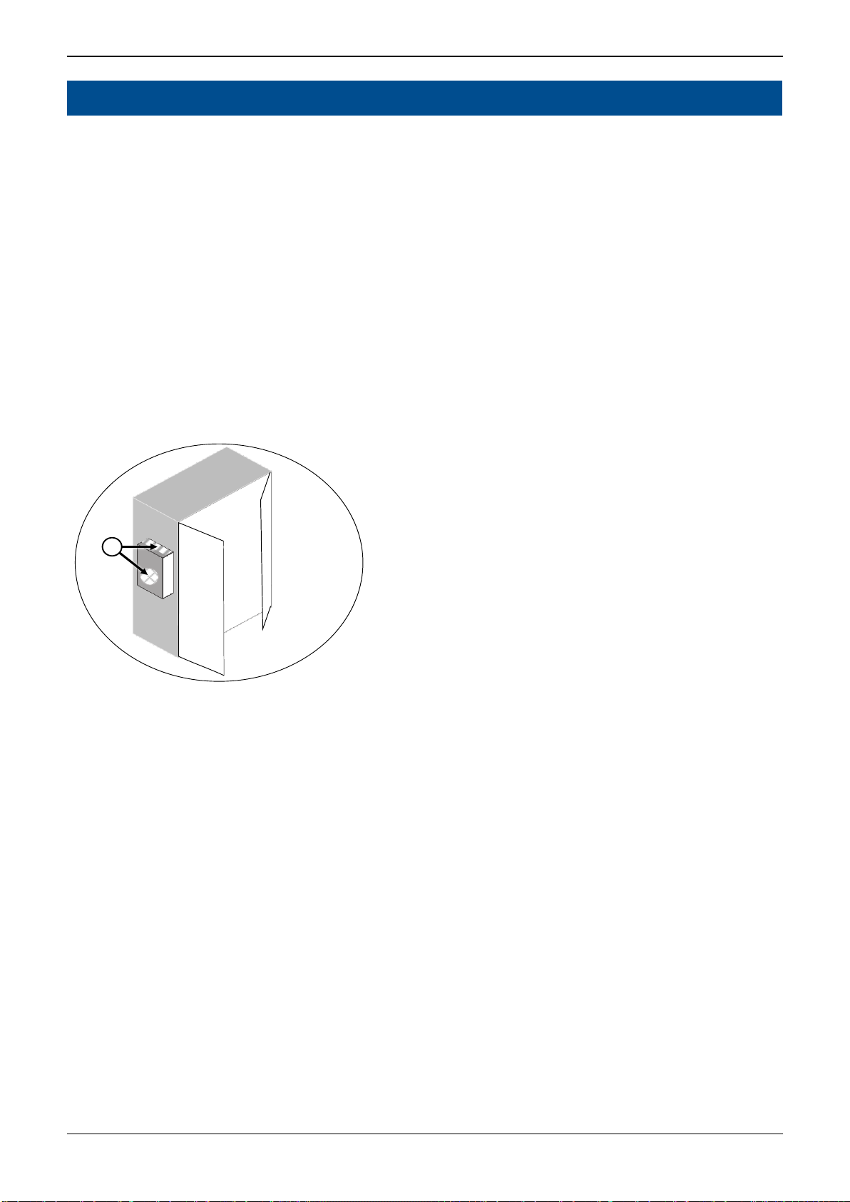
2.3 Thermal precautions
Figure 1 Hot surface areas
Info
During operation, the IMD can reach high surface temperatures. The temperature levels
depend on the ambient temperature inside and outside the cabinet.
Warning!
Risk of severe burns.
The heat sink of the IMD can reach high temperature.
Do not touch until the surface (see pos. 1 in Figure 1 on page 13 ) is cooled down.
Caution!
Risk of burns.
The sides of the IMD can reach medium high temperature.
Do not touch until the surface (see pos. 2 in Figure 1 on page 13 ) is cooled down.
2
1

IMD 100 Integration manual 4189360015 Rev. G Avoiding damage to the IMD
www.deif.com/wind-power Page 14 of 243
3. Avoiding damage to the IMD
Certain situations may result in product damage and should therefore be avoided by observing the
precautions described in this section. These situations are not likely to occur under normal use of the
IMD, but might occur in the lab or during service.
The situation list may not be comprehensive. Other, unknown situations that are not described in this
section could occur.
3.1 Connecting the safe energy
Possible damage: Damage to internal power components.
3.2 Switching mains ON and OFF
Possible damage: DC-link Pre-charge circuit damaged due to repeated MAINS ON and OFF
operations
How to avoid:
If the MAINS connections are switched ON and OFF more than once, wait 60 seconds
before switching ON after switch OFF.
3.3 Overloading the ballast resistor
Possible damage: Ballast circuit ((switch or resistor) damaged due to overload.
How to avoid:
•The ballast resistor value is adequate for the DC-link Vmax.
•Never use single pulse longer than 1 s during safe energy test.
•Wait 10 minutes (at 25ºC) if the IMD is restarted and the ballast resistor has been
loaded (hot)
3.4 Connecting the mains with overvoltage
Possible damage: Total damage to the IMD.
How to avoid:
The mains supply must never exceed the range specified in the Data sheet.
How to avoid:
If the safe energy was disconnected from the SE terminals, the mains supply must be
turned on before the safe energy is turned on.
IMD 100 Integration manual 4189360015 Rev. G Mechanical integration
www.deif.com/wind-power Page 15 of 243
4. Mechanical integration
This section describes the mechanical aspects of the IMD. See IMD 100 Datasheet for physical
dimensions.
4.1 Integrating the IMD in a cabinet
4.1.1 Environmental requirements
The IMD must be mounted in a closed cabinet where the requirements for ingress protection of
components do not exceed IP 20.
The IMD heatsink is mounted through a hole in the cabinet and requirements for ingress protection
outside the cabinet do not exceed IP 55 (IP 54 for IMD 122 B).
When designing the pitch system, pay attention to IMD location in the hub, to avoid debris entering the
heatsink (1). Take the hub rotation into account, so that loose objects are not funnelled into the
heatsink.
IP 55
IP 20
1
Figure 2 Environmental requirements and considerations
For other environmental requirements, see IMD 100 Datasheet.
4.1.2 Temperature considerations
This section describes the considerations concerning temperature and ventilation when designing the
cabinet in which the IMD is placed, and the location of the cabinet.
4.1.2.1 Personal safety considerations
The heat sink (both in and out) can get hot depending on the ambient temperature and the activity of
pitching the blade. If there is a risk of people touching the back of the IMD (the heat sink outside the
cabinet) it is recommended to implement measures to protect personnel such as physical guards,
information, or any other means.
IMD 100 Integration manual 4189360015 Rev. G Mechanical integration
www.deif.com/wind-power Page 16 of 243
Figure 3 Risk of heat hazard
4.1.2.2 Cabinet cooling considerations
The ambient temperature range defined in the IMD 100 Datasheet must be maintained at all times.
This also applies inside the cabinet, where the IMD itself also contributes with heat radiation, mainly
because part of the heat sink is located inside the cabinet. The IMD shuts down the output drive at
90 ºC, thereby the heat sink temperature will never exceed 90 ºC.
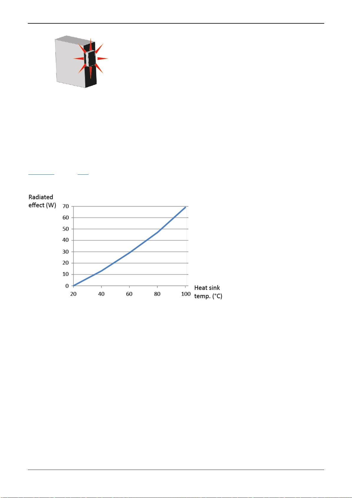
IMD 122:
Figure 4 on page 16 shows the heat radiation of the IMD inside the cabinet as a function of the heat
sink temperature. At this temperature, the heat contribution from the IMD inside the cabinet is
approximately 69 W.
Figure 4 Radiated heat from the IMD inside the cabinet

IMD 100 Integration manual 4189360015 Rev. G Mechanical integration
www.deif.com/wind-power Page 17 of 243
IMD 135:
Figure 5 on page 17 shows the heat radiation of IMD 135 inside the cabinet as a function of the heat
sink temperature. At this temperature, the heat contribution from the IMD inside the cabinet is
approximately 81 W.
Figure 5 Radiated heat from the IMD inside the cabinet
4.1.2.3 Free space around the IMD
Outside the cabinet, keep free space around the IMD at least as shown in Figure 6 on page 17 (IMD
122 C), Figure 7 on page 18 (IMD 122 B) and Figure 8 on page 18 (IMD 135). There must be
adequate ventilation in this space.
Inside the cabinet, keep at least 20 mm free space from the sides of the IMD and 80 mm free space
from top and bottom of the IMD. There must be adequate ventilation in this space.
Figure 6 IMD 122 C free space requirements
Note for IMD 122 C: The 100 mm indicated is recommended to enable easy replacement of the fan.
The minimum requirement due to temperature is 50 mm.
80 mm
80 mm
80 mm
20 mm
20 mm
25 mm
25 mm
Outside cabinet (back)
inside cabinet (front)
Heat sink
inside cabinet
80 mm
100 mm

IMD 100 Integration manual 4189360015 Rev. G Mechanical integration
www.deif.com/wind-power Page 18 of 243
Figure 7 IMD 122 B free space requirements
Figure 8 IMD 135 C free space requirements
Note for IMD 135: Consider the outside space (25 mm) around the IMD with regards to fan
replacement.
25 mm
80 mm
80 mm
20 mm
20 mm
25 mm
25 mm
Outside cabinet (back)
inside cabinet (front)
Heat sink
inside cabinet
80 mm
50 mm
80 mm
20 mm
20 mm
25 mm
25 mm
Outside cabinet (back)
inside cabinet (front)
Heat sink
inside cabinet
70 mm
136 mm
mm
80 mm
80 mm

IMD 100 Integration manual 4189360015 Rev. G Mechanical integration
www.deif.com/wind-power Page 19 of 243
4.1.3 Mounting of the IMD in the cabinet
A rectangle hole and 14/16 x 7 mm holes for M6 bolts must be made in the cabinet where the IMD is
to be mounted.
The holes for the bolts and heat sink are to be made according to the following drawing:
Figure 9 Cabinet cut-out drawing for IMD 122

Other manuals for IMD 100
3
This manual suits for next models
4
Table of contents
Other Deif DC Drive manuals


Popular DC Drive manuals by other brands


STG-BEIKIRCH
STG-BEIKIRCH M2 Series Technical information and operating instruction

Kinco
Kinco SV100 Series User Mannual

WITTUR
WITTUR Beamer 2 Series operating instructions

Oriental motor
Oriental motor Vextra PK264-E2.0A operating manual

KEBCO
KEBCO COMBIVERT F4-S instruction manual

Delta
Delta VFD-MS300 Series Quick setup instructions