Deka SOLAR Monoblock VRLA System Installation instructions
Monoblock VRLA System
Installation & Operating Manual

System Design ................................................1
Battery Operation
Temperature ....................................................1
Depth of Discharge (DoD) ..............................1
Charging ..........................................................1
Inverter/Charge Controller Settings..............1
Bulk............................................................2
Absorption..................................................2
Float ..........................................................2
Equalize ....................................................3
Maintenance ....................................................3
Battery Location
Space ..............................................................3
Floor Preparation ............................................3
Battery Racking System ..................................3
Ventilation ........................................................3
Environment ....................................................3
Operating Equipment ......................................4
Series/Parallel Wiring ......................................4
Sa ety Precautions
Procedures ......................................................
Receiving & Storage
Receiving Inspection ......................................
Unpacking........................................................
Storage ............................................................
Installation
General............................................................
Grounding........................................................
System Operation
Charging ..........................................................
Charging Parameters ....................................
Charge Current..............................................
State of Charge ..............................................
Record Keeping
Maintenance
Annual Inspection ............................................
Rectifier Ripple ................................................
Capacity Testing ..............................................
Glossary
Appendix A – Renewable Energy Worksheet..
Appendix B – Example of Typical 3 Stage
Charger..............................................................
Appendix C – Depth of Discharge vs. Freezing
Point
Appendix D – Capacity vs. Temperature..........
Appendix E – Voltage Compensation Chart ....
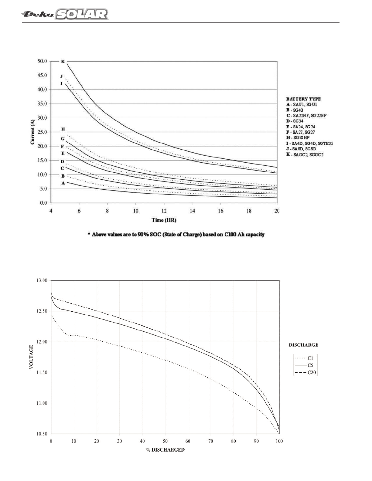
Appendix F
Charging Current vs. Charging Time Chart ..
Discharge Voltage Curve ..............................
Appendix G – Battery Maintenance Report ........
TABLE OF CONTENTS

1
SYSTEM DESIGN
Systems Design is the process of defining the architecture,
components, modules, interfaces, and load data for a system
to satisfy specified requirements. For a solar system these
components are the PV modules, inverter/charge controller
& batteries, as well as the different interfaces of those
components.
To properly size a battery/battery bank for a renewable energy
system the following parameters are required:
Load – Amount of DC current (Amps, Ah) or power (Watts,
Wh) a battery is required to supply to a DC load or AC loads
through an inverter.
Time – expressed in hours the battery will be required to
provide the load.
System Voltage – DC system operating voltage
Ambient Temperature – Average temperature of battery
room or enclosure.
Depth of Discharge (DoD) – The proportion of energy that
has been removed from a battery; typically in a 24hr period
Example: 100% DoD is removing all
of the energy from a battery.
Autonomy – Length of time PV system can provide energy to
load without energy from PV array
Design Margin - Factor (typically expressed as a percentage)
to allow for future load additions.
A Renewable Energy Worksheet is provided in Appendix A
listing the above requirements along with additional information
requirements
BATTERY OPERATION
There are several factors that affect the operation of the battery
concerning its ability to deliver capacity and life expectancy.
Temperature
Many chemical reactions are effected by temperature, and
this is true of the reaction that occurs in a storage battery.
The chemical reaction of a lead-acid battery is slowed down
by a lowering of the electrolyte temperature that results in
less capacity. A battery that will deliver 100% of rated
capacity at 77° F will only deliver approximately 65% of
rated capacity at 32°F.
At temperatures below 32°F (0°C) a battery can freeze
dependent on the DoD (Depth of Discharge). The higher the
DoD, the closer to 32°F (0°C) before the battery will freeze.
The graph in Appendix C should be consulted to verify the
DoD of the battery / battery bank at the end of the discharge
will not be susceptible to freezing in a particular application.
If the electrolyte would freeze, the internal damage would be
irreversible requiring the battery to be replaced.
xcessive heat will increase the natural corrosion factors of a
lead-acid battery. This increase corrosion of the positive plates
contributes greatly to reducing the overall life of the battery.
Depth o Discharge (DoD)
Depth of discharge is a function of design. The deeper the
discharge per cycle, the shorter the life of the battery. A
cycle is a discharge and its subsequent recharge regardless
of depth of discharge.
Systems should be designed for shallow discharges. The
result of shallower discharges is typically a larger capacity
battery at prolonged battery life.
A Cycle vs. DoD chart should be consulted to determine the
number of cycles at a specific DoD and the projected life in
years the battery / battery system will provide prior to need-
ing replacement.
Charging
Majority of battery capacity/life issues can be traced to
improper charging. Improper charging settings may lead to
an overcharging or undercharging condition.
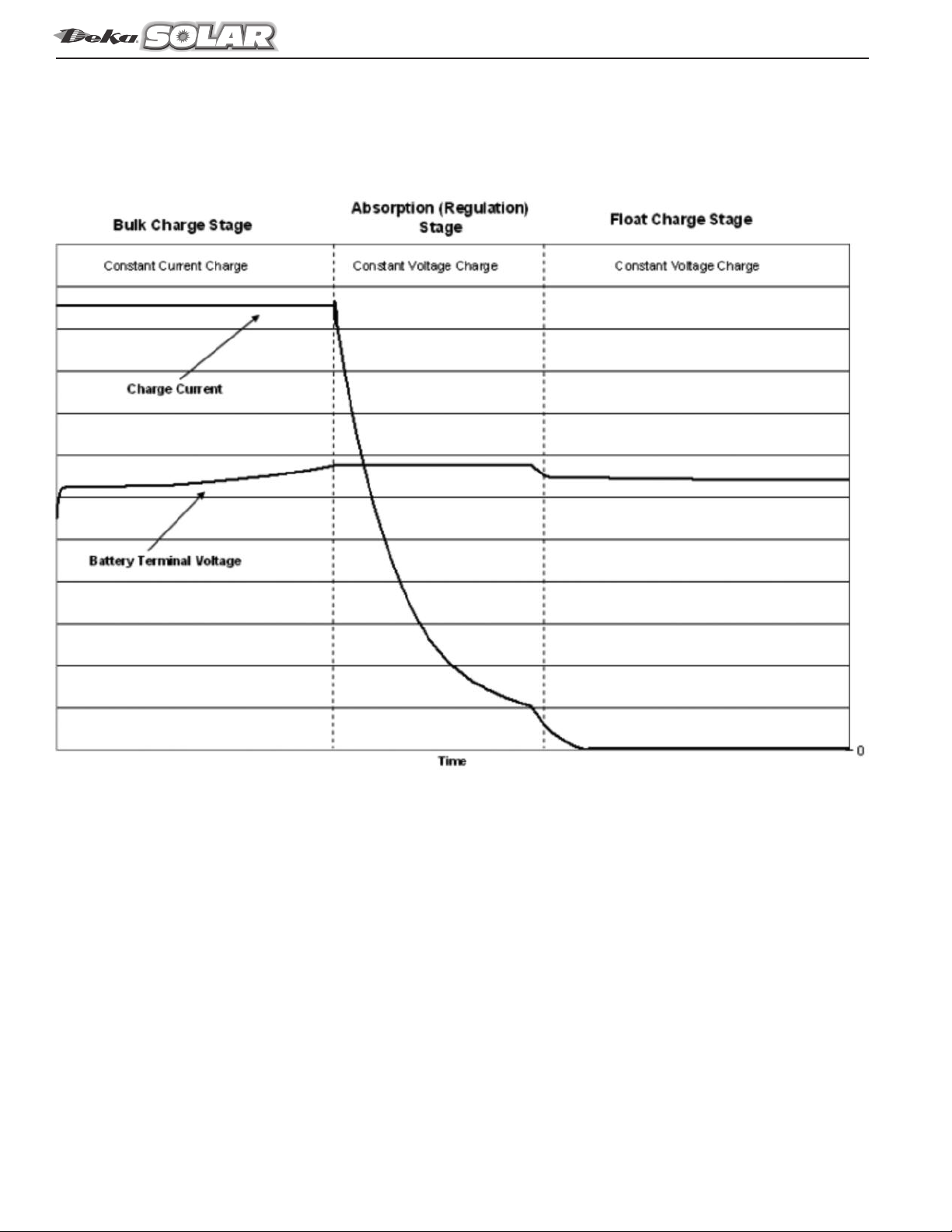
Typical Inverters/Charge Controllers charging lead-acid
batteries use 3 stage charging: Bulk, Absorption and Float
with an optional equalize stage. See Appendix B for an
example of a typical 3-stage charging curve.
Inverter/Charge Controller Settings
Proper Inverter/Charge Controller settings are necessary
to ensure peak battery performance and life. All bulk,
absorption, float and equalize settings should be verified they
are within the battery manufacturers settings. These settings
are included but not limited to; voltage, current and time.
Consult individual battery Installation & Operating manuals
for inverter/charge controller setting recommendations.
Default settings should not be presumed to be correct.
For battery systems located in an uncontrolled temperature
environment, temperature compensation must be used.
Bulk
Current is applied to the batteries at the maximum safe rate
they will accept until voltage rises to near (80-85%) full charge
level. The battery voltage rises because the charging current
that is provided by the battery charger is replenishing its
internal charge capacity. The charger current is flat (constant)
and the battery voltage is rising.
Maximum allowable charge voltage & current allowed by
the battery manufacturer should be used to ensure the most
energy is returned within the bulk stage.
Renewable nergy applications that depend on battery power as part of the system operation must be at
maximum performance at all times. To ensure this high rate of performance is achieved, the battery charging
system must be set properly. A battery/battery bank that is undercharged or overcharged will affect the
battery system performance & life, as well as the performance of the entire system.
Key factors that affect a batteries ability to provide the capacity and long life that is expected are: System
Design, Storage, Temperature, Depth of Discharge (DoD), Charging and Maintenance.

2
Bulk continued
Bulk Charge Stage Time Calculation:
Max Time ( r) = (Ahr x 1.2)/Avg. Current (A)
Ahr = Amp hours removed during discharge.
1.2 = Recharge multiplier
Avg. Current = Average current available
to battery from charger.
Note: Avg. current should be < maximum current limits
for installed battery. Charge current limits available
from your East Penn representative.
Max Time ( r) – Maximum charge time for battery to
reach 80% - 85% state of charge
Absorption
The charger will attempt to hold its output voltage constant
while the battery continues to absorb charge (draw charging
current) from the charger. The rate at which the battery con-
tinues to absorb charge in this mode gradually slows down.
The amplitude of the charger current is gradually decreasing.
The charge current is falling and the battery voltage is flat
(constant).
Some Inverter/Charge Controllers can either use time or
current to determine the length of the absorption stage.
Time regulated absorption is based on a predetermined time
after the battery has completed the bulk stage (charge voltage
has reached its maximum set point). A lead-acid battery is said
to be at 80% to 85% SOC (State of Charge) when the voltage
set point is met and the current starts to taper; considered the
start of absorption. The remaining time required to reach
100% SOC is based on ever changing factors: solar isolation
(summer vs. winter), ambient temperature, battery type
(flooded, VRLA), and battery age.
Absorption stage time should be set to optimize the available
sun hours during the winter and/or cloudy months. If improp-
erly set, there is a risk of undercharging the battery system.
It is recommended to set the absorption time to the maxi-
mum time setting possible to take advantage of all available
charging light regardless of time of year or weather issues.
Using this method, the sun availability will determine the
absorption time. Following this recommendation, there is no
risk of overcharging if the battery charge voltage is set within
the recommended settings.
The amount of available power (current) to the batteries is
important for getting a battery charged. Available power
(current) to the batteries is the remaining power (current) after
connected loads are satisfied. Maximum charge voltage and
current allowed by the battery manufacturer should be used to
ensure the most energy is returned to the batteries.
The below calculation will assist in identifying the necessary
maximum charge current for the system. If the calculation
shows the absorption time is greater than the minimum
average peak sun hours for the installation location, the
amount of available current to the batteries should be
increased, which could be accomplished by a larger array
or a secondary power source such as a generator.
Charge Current Verification:
FLOODED
C20 x 0.44/charge current available
Example:
Maximum Charge Current
Battery Rating: 1186 (C20)
2374A – Charge current (maximum)
1186Ah x 0.44/237 = 2.20 hrs
Minimum Charge Current
Battery Rating: 1186Ah (C20)
118A – Charge Current (minimum)
1186Ah x 0.44 / 118A = 4.42 hrs
VRLA (AGM & GEL)
C20 x 0.39 / charge current available
Maximum Charge Current
Battery Rating: 183Ah (C20)
55A – Charge current (maximum)
183Ah x 0.39 / 55A = 1.30 hrs
Minimum Charge Current
Battery Rating: 183Ah (C20)
18.3A – Charge Current (minimum)
183Ah x 0.39 / 18.3A = 3.90 hrs
Current regulated absorption is using the charge current to
determine battery state of charge, which eliminates a majori-
ty of the variables previously mentioned with time based
absorption (solar isolation, ambient temperature, battery
type). Charging in constant voltage, when a battery / battery
system reaches the absorption voltage setting, the current
will start to taper. The point at which the current stops taper-
ing or declining is referred to as the stabilizing current. This
is an indication that the battery is fully charged and the cur-
rent the battery / battery system is drawing is only needed to
keep the battery at the set voltage. This minimum or stabiliz-
ing current will change based on the charge voltage setting.
Battery manufacturer should be consulted for current set-
tings.
An additional option for determining the SOC of a battery is
monitoring the Ah (amp hour) removed from a battery dur-
ing a discharge and the amount of Ah returned during
charge; similar to a gas gauge in a car. The Ah in and out
should be monitored on a continuous basis to keep track of
the overall SOC not just from day to day.
Float
The voltage at which the battery is maintained after being
charged to 100% SOC (State of Charge) to maintain capacity
by compensating for self-discharge of the battery.
E ualize
A charge, at a level higher than the normal float voltage,
applied for a limited period of time, to correct inequalities of
voltage, specific gravity, or state of charge that may have
developed between the cells during service.
Note: Equalize charging not required on VRLA (AGM/Gel)
as part of a daily charge setup. Based on PV applications,
unpredictable recharge availability, periodic equalize may
be required.

3
E ualize continued
Charge Controller/Inverter charge setting recommendations
are detailed in System Operation section of this manual. A
voltage range is provided because of equipment setting
availability/limitations, however for optimal charge per-
formance all setting should be at the highest setting of the
battery range that the charge controller/inverter can handle.
Maintenance
I (Institute of lectrical and lectronics ngineers) suggests
batteries be checked on a monthly, quarterly and yearly basis.
ach time period requires different checks. A maintenance log
should be initiated at the time of installation.
Typical checks consist of voltage, specific gravity (not
required for VRLA) and visual inspections. Periodic verifica-
tion of voltages will ensure battery is being fully charged and
operating properly. If any conditions are found that are out of
specifications, corrections should be made.
A good battery maintenance program is necessary to protect
life expectancy and capacity of the battery. Reference IEEE
450 for Flooded batteries and IEEE 1188 for VRLA (Valve
Regulated Lead-Acid) batteries.
BATTERY LOCATION
When planning a battery system the following requirements
should be considered:
• Space
• Floor Preparation
• Battery Racking System
• Ventilation
• Environment
• Operating Equipment
Space
It is recommended that aisle space be provided in front of all
battery racks be a minimum of 36.0" (915mm). The design
should meet all applicable local, state and federal codes and
regulations.
Floor Preparation
It is recommended to consult with a structural engineer to
determine if the existing floor will withstand the weight of the
battery and the battery racking system. The floors in which the
battery will be located should have an acid-resistant coating.
Any battery spills should be neutralized with non-corrosive,
water based neutralizing chemical (ex: baking soda/water
solution) that is user safe and environmentally compliant.
The area should always be washed with clean water to remove
any acid neutralizing chemical residue.
Battery Racking System
The battery should not be installed directly on a floor. There
should be some type of barrier/racking between the floor and
the batteries. This barrier/racking should be sufficient to handle
the weight of the battery. The battery racking system must be
suitably insulated to prevent sparking and eliminate any
grounding paths.
Battery Racking System continued
Adequate space and accessibility for taking individual battery or
cell voltage, hydrometer readings and adding water should be
considered. If installed in an earthquake seismic zone, battery
racking system must be of sufficient strength and adequately
anchored to the floor. Battery rack design and anchoring should
be reviewed by a structural engineer.
Ventilation
It is the responsibility of the installer to provide detailed
methods or engineering design required by Federal, State
and local regulations to maintain safe levels of hydrogen in
battery rooms/enclosures.
The rate of hydrogen evolution is highest when the battery is
on charge. xplosive mixtures of hydrogen in air are present
when the hydrogen concentration is greater than or equal to
4% by volume. To provide a margin of safety, battery
room/enclosure must be ventilated to limit the accumulation of
hydrogen gas under all anticipated conditions. This margin of
safety is regulated by Federal, State and Local codes and is
typically limited to 1% to 2% by volume of the battery
room/enclosure.
Consult all applicable codes to determine specific margin of
safety. Hydrogen gas calculations can be determined by using
proper formulas.
Hydrogen gas is lighter than air and will accumulate, creating
pockets of gas in the ceiling. The ventilation system should be
designed to account for and eliminate this situation. Ventilation
system must be designed to vent to the outside atmosphere by
either natural or mechanical means in order to eliminate the
hydrogen from the battery room/enclosure.
Environment
Batteries should be located in a clean, cool and dry place and
isolated from outside elements. The selected area should be free
of any water, oil and dirt from accumulating on the batteries.
Operating Equipment
Battery systems are sized based on a specific load (Amps
or Watts) for a specific run time to a specific end voltage.
Battery performance is based on these values, as measured
at the battery terminals.
For proper operation of the battery system the following should
be considered:
• Distance between battery system and operating systems
should be kept at the shortest distant possible
• Cables are to be of proper gauge to handle system loads
and minimize voltage drops.
• All cable lengths from battery system to operating system
should be of the same wire gauge and length.
The above is to ensure the battery cable used will be able to
carry the charge/discharge current & minimize the voltage drop
between equipment.
lectrical equipment should not be installed above the batteries,
because of the possibility of corrosive fumes being released
from the battery(s).
4
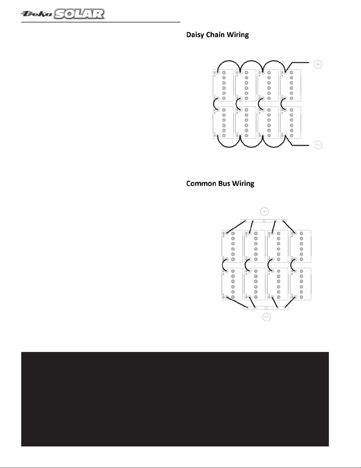
Series/Parallel Wiring
Series and parallel wiring of batteries as well as battery to
inverter/charge controller wiring should be designed to
minimize voltage drop. Wire gauge, wire length as well as
interbattery connection layout are all variables in reducing volt-
age drop as well as providing battery balance between parallel
battery strings.
Proceeding are examples of common wiring layouts with
narrative of the advantages and / or disadvantages of each.
Daisy Chain Wi ing a wiring scheme in which multiple
devices are wired together in sequence. All interconnecting
wiring should be of same length to minimize voltage drop.
Disadvantages:
• The interunit cables are required to increase in gauge
size to accommodate the increase in current of each
connected string.
• Maintenance and battery diagnostics require the entire
battery system to be disconnected from the renewable
energy system, leaving no back up energy source.
• Wiring connection assessment difficult to follow with
multiple wirings connected to same battery terminal,
increasing chance of re-connection wiring errors.
Common Bus Wi ing a wiring scheme in which same polarity
terminals are connected to a single termination point. All inter-
connecting wiring should be of same length to minimize volt-
age drop.
Advantages:
• Cables can be of same gauge.
• Maintenance and battery diagnostics can be performed
on a single string while maintaining a level of back up
energy source from the other strings staying connected
to the renewable energy system.
• Wiring connection assessment simplified by single
ONLY TRAINED AND AUTHORIZED PERSONNEL SHOULD
INSTALL, REPAIR OR CHARGE BATTERIES.
When used properly, a lead-acid renewable energy battery is a safe, dependable source of electrical
power. However, if proper care and safety precautions aren’t exercised when handling a battery, it can
be an extremely dangerous piece of equipment.
There are four hazardous elements in a lead-acid battery: sulfuric acid, explosive gases, electricity, and
weight.

5
SAFETY PRECAUTIONS
Although all valve-regulated batteries have the electrolyte
immobilized within the battery, the electrical hazard associated
with batteries still exists. Work performed on these batteries
should be done with the tools and the protective equip-
ment listed below. Valve-Regulated battery installations
should be supervised by personnel familiar with batteries and
battery safety precautions.
WARNING: Risk of fire, explosion or burns. Do not
disassemble, heat above 40°C, or incinerate.
Protective E uipment
Although VRLA batteries can vent or leak small amounts of
electrolyte, electrical safety is the principle but not the only
concern for safe handling. Per I 1188 recommendations,
the following minimum set of equipment for safe handling of
the batteries and protection of personnel shall be available:
1. Safety glasses with side shields, or goggles, or face
shields as appropriate. (Consult application specific
requirements)
2. lectrically insulated gloves, appropriate for the installation.
3. Protective aprons and safety shoes.
4. Portable or stationary water facilities in the battery vicinity
for rinsing eyes and skin in case of contact with acid elec-
trolyte.
5. Class C fire extinguisher.
6. Acid neutralizing agent.
7. Adequately insulated tools (as defined by ASTM F1505
“Standard Specification for Insulated and Insulating Hand
Tools).
8. Lifting devices of adequate capacity, when required.
Procedures
The following safety procedures should be followed during
installation:
(Always wear safety glasses or face shield when working on
or near batteries.)
1. These batteries are sealed and contain no free electrolyte.
Under normal operating conditions, they do not present
any acid danger. However, if the cell jar or cover is dam-
aged, acid could be present. Sulfuric acid is harmful to
the skin and eyes.
Flush affected area with water immediately and consult a
physician if splashed in the eyes.
Consult SDS fo additional p ecautions and fi st aid measu es.
SDS sheets can be obtained at
.eastpennmanufacturing.com
2. Prohibit smoking and open flames, and avoid arcing in the
immediate vicinity of the battery.
3. Do not wear metallic objects, such as jewelry, while work-
ing on cells. Do not store un-insulated tools in pockets or
tool belt while working in vicinity of battery. Keep the top
of the battery string dry and clear of tools and other for-
eign objects.
4. Provide adequate ventilation (per IEEE standard 1187
and/or local codes) and follow recommended charging
voltages.
5. Never remove or tamper with the pressure relief valves,
except for cell replacement. Warranty void if vent valve is
removed.
6. Inspect flooring and lifting equipment for functional
adequacy.
7. Adequately secure cell modules, racks, or cabinets to the
floor.
8. Connect support structures to ground system in
accordance with applicable codes.
RECEIVING & STORAGE
Receiving Inspection
Upon receipt, and at the time of actual unloading, each pack-
age should be visually inspected for any possible damage or
electrolyte leakage. If either is evident, a more detailed inspec-
tion of the entire shipment should be conducted and noted on
the bill of lading. Record receipt date, inspection data and
notify carrier of any damage.
Unpacking
1. Always wear eye protection.
2. Check all batteries for visible defects such as cracked
containers, loose terminal posts, or other unrepairable
problems. Cells with these defects must be replaced.
3. Check the contents of the packages against the packaging
list. Report any missing parts or shipping damage to your
ast Penn agent or ast Penn Mfg. Co. immediately.
4. Never lift batteries by the terminal posts.
Storage
1. Cells should be stored indoors in a clean, level, dry, cool
location. Recommended storage temperature is 0°F to
90°F (–18°C to 32°C).
2. Stored lead-acid batteries self discharge and must be
given a boost charge to prevent permanent performance
degradation.
0°F to 77°F (-18°C to 25°C) storage:
Batteries should be recharged six months from date of
manufacture.
>77°F (25°C) storage:
Use the chart below for recharge intervals. Voltage readings
should be taken on a monthly basis. Batteries that reach
12.60V per 12V battery (6.30 per 6V battery) or less should
be recharged regardless of scheduled interval. Record dates
and conditions for all charges during storage.
3. If a boost charge is required; the recommended charge is
24 hours at a constant voltage equal to 14.40V per 12V
battery (7.20V per 6V battery).
4. Do not store beyond 12 months.
INSTALLATION
General
Caution should be taken when installing batteries to ensure
no damage occurs. Batteries shall not be dropped, slid, or
placed on rough or uneven surfaces such as tray lips or
grated flooring. Mishandling of batteries could result in
equipment damage or human injury. ast Penn will not be
liable for damage or injury as a result of mishandling or
misuse of the product.

6
Charging Parameters
Charge Voltage
Bulk Charge:
Current limited to 30% of C20 or 6 times I20.
Absorption Charge:
12.10V to 14.40V per 12V battery
Float Charge:
13.44V to 13.56V per 12V battery
Equalize:
14.40V to 14.60V per 12V battery
Note: Divide values in half for 6-volt battery.
Temperature Compensation
Battery voltage should be adjusted for ambient temperature
variations.
3mV per °C (1.8°F) per cell
18mV per 12V battery
9mV per 6V battery
For temperatures above 77°F (25°C) subtract and for temper-
atures below 77°F (25°C) add.
Consult Voltage Compensation Chart in Appendix D for
temperature compensation voltage maximum and minimum
limits.
The average battery operating temperature should not exceed
95°F (35°C) and should never exceed 105°F (40.5°C) for more
than an eight-hour period. Operating at temperatures greater
than 77°F (25°C) will reduce the operating life of the battery. If
operating temperatures are expected to be in excess of
95°F (35°C), contact East Penn for recommendations.
Discharging at temperatures less than 77°F (25°C) will reduce
the capacity of the battery.
Charge Current
To properly determine the amount of charge current required
the following variables are to be considered:
• DoD (Depth of Discharge)
• Temperature
• Size & efficiency of the charger
• Age and condition of battery(ies)
Maximum charge current should be limited to 30% of the C20
Ah rate for the battery(ies) being used in the system.
Example: 8G24 C20 rate – 73.6Ah
Max. recharge rate: 73.6Ah x 0.3 = 22.1A
Consult Charging Current vs Charging Time chart in
Appendix E as a guide line to determine recharge time from
0% to 90% state of charge at an initial charge current.
Discharge Voltage Curve
To estimate battery voltage during a constant current dis-
charge at various DoD (Depth of Discharge) consult chart
Discharge Voltage Curve in Appendix E.
NOTE: Battery voltage can vary depending on tempera-
ture, age, and condition of battery.
Grounding
When grounding the battery system, proper techniques should
be applied per electrical standards, such as N C and/or local
codes, as well as User Manual of specific application.
BATTERY ASSEMBLY
(Always wear eye protection.)
1. Set up the batteries so that the positive post (+) of one
battery is connected to the negative post (–) of the next
battery for all series connections.
2. All battery electrical contact surfaces shall be cleaned by
rubbing gently with a non-metallic brush or pad before
installing connectors. No-Ox-ID grease can be used but is
not required.
3. Install all electrical connectors / cables and bolting
hard¬ware loosely to allow for final alignment of batteries.
Torque to manufacturer recommendations.
4. After torquing, read the voltage of the battery string to
ensure the individual batteries are connected correctly. The
total voltage should be approximately equal to the number
of batteries times the measured voltage of one battery
(when connected in series). If the measurement is less,
recheck the connections for proper voltage and polarity.
5. Read and record connection resistance and note the
method of measurement. This helps determine a satisfac-
tory initial installation and can be used as a reference
for future maintenance requirements. See Appendix B,
recording forms, in the back of the manual. Clean, remake
and re-measure any connection having a resistance meas-
urement greater than 10% of the average of all the same
type of connections.
6. Battery performance is based on the output at the battery
terminals. Therefore, the shortest electrical connections
between the battery system and the operating equipment
results in maximum total system performance.
7. Cable size selection should be determined by current
carrying requirements as well as providing a minimum
voltage drop between battery system and operation
equipment. Proper techniques should be applied per
electrical standards, such as N C and/or local codes.
Note: xcess voltage drop will reduce the support time
of the battery system.
SYSTEM OPERATION
There are several factors that affect the operation of the battery
system concerning its ability to deliver capacity and life
expectancy. Many chemical reactions are affected by tempera-
ture, and this is true of the reaction that occurs in a storage
battery. The chemical reac¬tion of a lead-acid battery is slowed
down by a lowering of the electrolyte temperature that result in
less capacity. A battery that will deliver 100% of rated capacity
at 77° F (25°C) will only deliver 65% of rated capacity at 32°F
(0°C).
Charging
Consult Charger User Manual of specific application for
Safety and Operating requirements.
For cyclic applications it is important that the battery system
be charged fully after each discharge. It is recommended that
108% to 115% of the Ah (Amp Hour) capacity removed from
the battery system be replaced after each discharge. This addi-
tional Ah is to compensate for any efficiency losses between
the battery charger and the battery system.
7
State of Charge
Battery state of charge can be determined by measuring the
open circuit voltage. Consult the below table.
State of Charge vs. Open Circuit Voltage*
NOTE: Divide values in half for 6-volt battery(ies)
*The “true” O.C.V. of a battery can only be determined after the
battery has been removed from the load (charge / discharge)
for 24 hours.
RECORD KEEPING
Voltages, Temperatures & Ohmic Readings
Consult User Manual of specific application for additional
Safety & Operating requirements.
Record keeping is an important part of battery mainte-nance
and warranty coverage. This information will help in establish-
ing a life history of the battery and inform the user if and when
corrective action needs to be taken. (Refer to Appendix B,
Battery Maintenance Report).
After installation and the batteries are at a fully charged
condition, the following data should be recorded:
Depending on application, some of the following recommen-
dations may not apply.
• Battery and/or string terminal voltage
• Charger voltage
• Individual battery float / charge voltages
• Individual battery ohmic readings**
• Ambient temperatures
• Terminal connections should be checked to verify all
connections are properly torques. Micro-ohm readings
should be taken across every connection. Refer to meter
manufacturer’s instructions for proper placement of
probes. If any reading differs by more than 20% from its
initial installation value, re-torque the connections. If the
reading still remains high, clean contact surfaces
according to installation portion of this manual.
** Note: To provide accurate consistent values, battery sys-
tems must be fully charged, at same temperature and probes
placed at same location each time readings are taken.
MAINTENANCE
Always wear eye protection when working on or near batteries.
Keep sparks and open flames away from batteries at all times.
Consult User Manual of specific application for additional
Safety & Operating requirements.
Annual Inspection
Depending on the application, some of the following recom-
mendations may not apply.
1. Conduct a visual inspection of the battery(ies).
2. Record battery and /or string voltage. The accuracy of the
DMM (Digital Multimeter) must be 0.05% (on dc scale) or
better. The DMM must be calibrated to NIST traceable
standards. Because voltage readings are affected by dis-
charge and recharges, for cyclic applica¬tions, the
battery(ies) must be in a fully charged condition prior to
taking readings. Batteries should be within ± 0.30 volts (+
0.15 volts for 6V) of the average battery float voltage.
3. Record charger voltage.
4. Record the ambient temperature.
5. Record individual battery ohmic readings.***
6. Record all interunit and terminal connection resistances.
Micro-ohm readings should be taken during this
inspec¬tion. If any reading is greater than 20% from initial
readings, retorque the connection. Recheck the micro-ohm
reading. If the reading remains high, clean contact surface
according to installation portion of this manual.
*** Note: To provide accurate / consistent values, battery(ies)
must be fully charged, at same temperature and probes placed
at same location each time readings are taken.
Rectifier Ripple Voltage
FREQUENCY
Ripple that has a frequency greater than 667Hz (duration less
than 1.5ms) is acceptable, unless it is causing additional battery
heating.
Ripple that has a frequency less than 667Hz (duration greater
than1.5ms), must meet the following voltage specification to
be acceptable.
VOLTAGE
Ripple voltage shall be less than .5% peak to peak of the
manufacturer’s recommended string voltage.
Battery Cleaning
Batteries, cabinets, racks, and modules should be cleaned with
clean water. If neutralizing is required, use a mixture of baking
soda and water. Use clean water to remove baking soda
residue. Never use solvents to clean the battery(ies).
Capacity Testing
Capacity tests should not be run unless the battery’s operation
is questionable. Do not discharge the battery(ies) beyond the
specified final voltage. When discharging at higher rates, extra
connectors may be required to prevent excessive voltage drop.
When performing capacity testing and recording data use
applicable standard and/or User Manual.
Should it be determined any individual battery(ies) or cell(s)
need to be replaced, contact your nearest ast Penn agent or
ast Penn Mfg. Co.
To determine if a battery can deliver its rated capacity, a test
discharge, or capacity test, can be performed. This test helps
determine the “health” of a battery and whether or not it
should be replaced.
Only experienced battery technicians should be allowed to
prepare a battery for discharge testing and to conduct the
actual discharge test.
% Charge Gel AGM
100 12.85 or higher 12.80 or higher
75 12.65 12.60
50 12.35 12.30
25 12.00 12.00
0 11.80 11.80

8
Capacity Testing continued
The test is conducted by discharging a fully charged battery at
a specific rate until the battery voltage drops to a
predeter¬mined volts per battery, times the number of batter-
ies in the battery system. By noting the time elapsed between
when the battery was put on discharge and when the final volt-
age was reached, you can determine whether the battery is
delivering its rated capacity:
1. Give the battery an equalizing charge until the current has
stabilized. Start the test and record the starting time.
2. Record individual battery voltages and overall battery sys-
tem voltages during the first hour at 10 minutes, 30 min-
utes and then 60 minutes. After the first hour, take hourly
readings until the first battery voltage reaches 10.80 volts
per battery. From this point on, record the voltage of the
batteries every 5 minutes. monitor the voltage of the low
batteries and as the voltage of each battery drops below
the predetermined final voltage, record the time.
3. When the majority of the batteries reach termination value,
stop the test. Don’t let any battery go into reversal.
For example, if the test was run at the 360 minute rate was ter-
minated after 336 minutes; the capacity percentage would be
93%
4. If the battery system delivers 50% or more of its rated
capacity, it can be returned to service. If the test indicates
less than 50% of the battery’s rated capacity is being deliv-
ered, the battery system should be either repaired or
replaced, depending upon its age and overall condition.
For more detailed information on capacity testing, contact
East Penn Manufacturing Company or your local authorized
East Penn Representative.
GLOSSARY:
AGM – Absorbed Glass Mat – A class of VRLA (Valve
Regulated Lead-Acid) battery in which the electrolyte is
absorbed into a glass mat.
Ambient Temperature – The average temperature of the
battery room. Temperatures below 77°F (25°C) will reduce
battery capacity. Temperatures above 77°F (25°C) will
reduce battery service life.
Amp our (Ah) – Amps times Hours
Battery fficiency – The amount of Ah return required to
achieve full SOC vs. the amount of Ah removed during dis-
charge. Require 110% to 115% Ah return
Capacity – The capacity of a battery is specified as the
number of Amp-Hrs that the battery will deliver at a specific
discharge rate and temperature. The capacity of a battery is
not a constant value and is seen to decrease with increasing
discharge rate.
C20 –Battery capacity measured in Ah (amp hour) at the
20hr rate.
End Voltage – The minimum voltage at which a DC system
will operate.
Flooded – A battery in which the products of electrolysis
and evaporation are allowed to escape to the atmosphere
as they are generated. lectrolyte is free flowing throughout
the battery.
Gel – A class of VRLA (Valve Regulated Leda-Acid) battery
in which the electrolyte is immobilized in a gel form (sulfuric
acid mixed with silica)
Parallel – A circuit that provides more than one path for the
flow of current. A parallel arrangement of batteries (usually
of like voltages and capacities) has all positive terminals
connected to a conductor and all negative terminals con-
nected to another conductor. If two 12-volt batteries of 50
ampere-hour capacity each are connected in parallel, the
circuit voltage is 12 volts, and the ampere-hour capacity of
the combination is 100 ampere-hours.
Series – A circuit that has only one path for the flow of
current. Batteries arranged in series are connected with
negative of the first to positive of the second, negative of the
second to positive of the third, etc. If two 12-volt batteries of
50 ampere hours capacity each are connected in series, the
circuit voltage is equal to the sum of the two battery volt-
ages, or 24 volts, and the ampere-hour capacity of the com-
bination is 50 ampere-hours.
SOC (State of Charge) – The amount of deliverable
low-rate electrical energy stored in a battery at a given time
expressed as a percentage of the energy when fully charged
and measured under the same discharge conditions. If the
battery is fully charged the “SOC” is said to be 100%.
Temperature Correction – A factor used to compensate for
battery capacity and/or adjust battery voltage at ambient
temperatures greater than or less than 77°F (25°C).
Undercharge (Deficit charge) – Charging a battery with less
ampere-hours (Ah) than is required to return the battery to
its initial state-of-charge. This results in a reduction in the
battery state-of-charge.
VPC – Volts per Cell
VRLA – Valve Regulated Lead Acid – a lead-acid cell/battery
that is sealed with exception of a valve that opens to the
atmosphere when the internal gas pressure exceeds atmos-
pheric pressure by a pre-selected amount. VRLA batteries
provide a means for recombination of internally generated
oxygen and the suppression of hydrogen gas evolution to
limit water consumption

9
APPENDIX A
Completing all parameters ensures accurate battery sizing.
Worksheet to be submitted to sales representative for battery recommendation.
10
APPENDIX B
Example of typical 3 stage charger

11
APPENDIX C
Depth of Discharge vs. Freezing Point

12
APPENDIX D
Capacity vs. Operating Temperature

13
APPENDIX E
Voltage Compensation Chart
!
!
!
!
!
!
!
!
!
!
!
!
!
!
!
!
!
!
!
!
!
!
!
!
!
!
!
!
!
!
!
!
!
!
!
!"#
$%&'(#
")'*+,-./0&*1(2&3#
!$#
4235#
4'65#
≥
!"#
$!%!&#
$!%'&#
$(%()#
≥
*"#
!(#
$!%!(#
$!%'(#
$(%(&#
*!%&#
!!#
$!%!'#
$!%''#
$(%((#
*$%(#
!&#
$!%!+#
$!%'+#
$(%("#
,*%'#
!$#
$!%!*#
$!%'*#
$(%(+#
,+%,#
!)#
$!%($#
$!%+$#
$(%(*#
,'%)#
&*#
$!%(!#
$!%+!#
$(%"$#
,(%&#
&,#
$!%("#
$!%+"#
$(%"!#
,&%(#
&+#
$!%('#
$!%+'#
$(%"(#
,)%'#
&'#
$!%(,#
$!%+,#
$(%"'#
+,%,#
&"#
$!%")#
$!%,)#
$(%",#
++%)#
&(#
$!%"&#
$!%,&#
$(%')#
+"%&#
&!#
$!%"(#
$!%,(#
$(%'&#
+!%(#
&&#
$!%""#
$!%,"#
$(%'!#
+$%'#
&$#
$!%"+#
$!%,+#
$(%'"#
'*%,#
&)#
$!%"*#
$!%,*#
$(%'+#
',%)#
$*#
$!%'$#
$!%*$#
$(%'*#
''%&#
$,#
$!%'!#
$!%*!#
$(%+$#
'(%(#
$+#
$!%'(#
$!%*(#
$(%+&#
'&%'#
$'#
$!%''#
$!%*'#
$(%+(#
')%,#
≤
$"#
$!%',#
$!%*,#
$(%+'#
≤
"*#
Note: 1. Above values based on 12-volt battery
2. Divide above values in half for 6-volt battery.
14
APPENDIX F
Charging Current vs Charging Time chart
Discharge Voltage Curve
!
!
!
!
!
!
!
!

APPENDIX G

Notes:
E.P.M. Form No. 2478. 6/19 © 2019 by EPM Printed in U.S.A.
An East Penn Manufacturing Co. Subsidiary
1-800-372-9253. www.mkbattery.com
e-mail: sales@mkbattery.com
www.dekabatteries.com
All data subject to
change without notice.
No part of this document may
be copied or reproduced,
electronically or mechanically,
without written permission
from the company.
Table of contents
Other Deka Camera Accessories manuals

Deka
Deka Unigy II AVR45 Series User manual

Deka
Deka FastCharge F35 User manual

Deka
Deka Unigy I User manual

Deka
Deka EZ LINK D35 User manual

Deka
Deka 8A User manual

Deka
Deka unigy II SPACESAVER Non-Interlock AVR 45 AH User manual

Deka
Deka unigy I User manual

Deka
Deka unigy User manual

Deka
Deka Unigy II User manual

Deka
Deka Dominator Gel-Mate SVRLA G45 User manual


Popular Camera Accessories manuals by other brands

Logitech
Logitech CIRCLE 2 quick start guide

VADDIO
VADDIO WALLVIEW DVI/HDMI HD-20 Installation and user guide

RODE Microphones
RODE Microphones VideoMic instruction manual

Aigis Mechtronics
Aigis Mechtronics HS9383S-2HP Installation and operating instructions

Axis
Axis A4020-E user manual

Glide Gear
Glide Gear LEIOS SMOOTH-C user manual


