Deka Unigy II User manual
NEBS CERTIFIED UNIGY II SYSTEM
NC4-2000 125 AH
Installation and Operation Manual
Califor ia
Propositio 65
War i g:
Batteries, battery posts, terminals and related accessories
contain lead and lead compounds, and other chemicals known
to the state of California to cause cancer and birth defects or
other reproductive harm. Wash hands after handling.
®

$)(593(&$65,104
527)'7-9)48-30)17
52')(85)6
(&(,7,0*513$*(
)')-9-1+163)'7-21
"13%'.-1+
725%+)
045$..$5,10
)1)5%/
5281(-1+
/)'75-'2()*25%-17)1%1')'')66
/2251',25-1+2(8/)55%1+)0)176
%5(:%5)!2548))48-5)0)176
945(/045$..$5,104
;67)0 ,-30)17
2(8/)167%//%7-21
(..045$..$5,10
.(&53,&$.100(&5,10
211)'72566)0&/;
!)50-1%/66)0&/;
-1%/66)0&/;,)'.52')(85)
%*)7; ,-)/(66)0&/;
!23527)'7-21 ,-)/(167%//%7-21
945(/2(3$5,104
,%5+)5#2/7%+)
3)5%7-1+!)03)5%785)6
)//#2/7%+)
)'7-*-)5-33/)#2/7%+)
(&13'((2,0*
#2/7%+)6!)03)5%785)6
,0-')%(-1+6
$,05(0$0&(
118%/163)'7-21
)'7-*-)5-33/)#2/7%+)
%77)5;/)%1-1+
%3%'-7;!)67-1+
.((7((..(/17$.31&('63(
0,*9
&,' 1.6/(4!(,*+54
"
#
FLUSH EYES
IMMEDIATELY
WITH WATER.
GET
MEDICAL
HELP
FAST.
SULFURIC ACID
CAN CAUSE
BLINDNESS OR
SEVERE BURNS.
NO
•SPARKS
•FLAMES
•SMOKING
SHIELD
EYES.
EXPLOSIVE GASES
CAN CAUSE BLIND-
NESS OR INJURY.
HIGH
VOLTAGE...
RISK OF SHOCK.
DO NOT TOUCH
UNINSULATED
TERMINALS OR
CONNECTORS.
DO NOT REMOVE VENT VALVE.
WARRANTY VOID IF VENT VALVE IS REMOVED.
VENTILATE WELL WHEN IN AN ENCLOSED
SPACE AND WHEN CHARGING.
SEE INSTALLATION, MAINTENANCE AND OPERATION
INSTRUCTIONS FOR IMPORTANT SAFETY PRECAUTIONS.
DANGER
BATTERIES
AND OTHER RELATED PARTS
CONTAIN LEAD
Form No: 1314 Rev. 5/08 Must be posted in workplace near batteries.
WARNING:
Battery posts, terminals and related accessories
contain lead and lead compounds, chemicals
known to the State of California to cause
cancer and reproductive harm.
Batteries also contain other chemicals known
to the State of California to cause cancer.
WASH HANDS AFTER HANDLING!
Califor ia
Propositio 65
War i g:
Batteries, battery posts, terminals and related accessories con-
tain lead and lead compounds, and other chemicals known
to the state of California to cause cancer and birth defects or
other reproductive harm. Wash hands after handling.
2

SAFETY PRECAUTIONS
Although all valve-regulated batteries have the electrolyte
immobilized within the cell, the electrical hazard associated
with batteries still exists. Work performed on these
atteries should e done with the tools and the protective
equipment listed elow. Valve-regulated battery installations
should be supervised by personnel familiar with batteries
and battery safety precautions.
Protective Equipment
To assure safe battery handling, installation and
maintenance, the following protection equipment should
be used:
1. Safety glasses or face shield
2. Acid-resistant gloves
3. Protective aprons and safety shoes
4. Proper lifting devices
5. Properly insulated tools
Procedures
The following safety procedures should be followed during
installation: (Always wear safety glasses or face shield
when working on or near atteries.
)
1. These batteries contain no free-flowing electrolyte.
Under normal operating conditions, they do not present
any acid danger. However, if the battery jar or cover is
damaged, acid could be present. Sulfuric acid is harmful
to the skin and eyes. Flush affected area with water
immediately and consult a physician if splashed in the
eyes.
2. Prohi it smoking and open flames, and avoid arcing in
the immediate vicinity of the attery.
3. Do not wear metallic objects, such as jewelry, while
working on batteries. Do not store un-insulated tools in
pockets or tool belt while working in vicinity of battery.
4. Keep the top of the battery dry and clear of tools and
other foreign objects.
5. Provide adequate ventilation (per IEEE standard 1187
and/or local codes) and follow recommended charging
voltages.
6. Extinguishing media: Class ABC extinguisher.
Note: CO2may be sed b t not directly on the cells
d e to thermal shock and potential cracking of cases.
7. Never remove or tamper with the pressure relief valves.
Warranty void if vent valve is removed.
8. Inspect all flooring and lifting equipment for functional
adequacy.
9. Adequately secure battery modules, racks, or cabinets
to the floor.
10. Connect support structures to ground system in
accordance with applicable codes.
11. The below IEEE Standards contain additional information.
Other standards may be relevant to your specific applica-
tion.
IEEE 1187 – Recommended Practice for Installation
Design of VRLA Batteries
IEEE 1188 – Recommended Practice for Maintenance,
Testing, of VRLA Batteries
IEEE 1189 – Selection of VRLA Batteries for Stationary
Applications
RECEIVING & STORAGE
Receivin Inspection
Upon receipt, and at the time of actual unloading, each pack-
age should be visually inspected for any possible damage or
electrolyte leakage. If either is evident, a more detailed
inspection of the entire shipment should be conducted and
noted on the bill of lading. Record receipt date, inspection
data and notify carrier of any damage.
Unpackin
1. Always wear eye protection.
2. Check for visible defects such as cracked containers,
loose terminal posts, or other unrepairable problems.
Batteries with these defects must be replaced.
3. Check the contents of the package against the packaging
list. Report any missing parts or shipping damage to
your East Penn agent or East Penn Mfg. Co. immediately.
4. Never lift batteries by the terminal posts.
5. When lifting batteries, the proper equipment is needed
such as a forklift or a portable crane. Always check the
lifting capacities of the equipment being used and never
lift more than one module at a time by the module
mounting holes.
Stora e
1. Cells should be stored indoors in a clean, level, dry, cool
location. Recommended storage temperature is 0˚F to
90˚F (–18˚C to 32˚C).
2. Stored lead-acid batteries self discharge and must be
given a boost charge six months from the date of
manufacture to prevent permanent performance
degradation. Record dates and conditions for all charges
during storage.
3. Recommended charge during storage is at a constant
voltage of 0.05 volts per cell greater than recommended
float voltage for 24 hours. Reference voltage chart in
SYSTEM OPERATION section.
4. Do not store beyond 12 months.
5. Store in horizontal position only.
DANGER
SHIELD
EYES.
EXPLOSIVE
GASES CAN CAUSE
BLINDNESS OR INJURY.
HIGH VOLTAGE...
RISK OF SHOCK.
DO NOT TOUCH
UNINSULATED
TERMINALS OR
CONNECTORS.
VENTILATE WELL WHEN IN AN ENCLOSED
SPACE AND WHEN CHARGING.
SEE INSTALLATION, MAINTENANCE AND OPERATION
INSTRUCTIONS FOR IMPORTANT SAFETY PRECAUTIONS.
NO
•SPARKS
•FLAMES
•SMOKING
SULFURIC
ACID
CAN
CAUSE
BLINDNESS OR
SEVERE BURNS.
FLUSH EYES
IMMEDIATELY
WITH WATER.
GET
MEDICAL
HELP
FAST.
DO NOT REMOVE VENT VALVE.
WARRANTY VOID IF VENT VALVE IS REMOVED.
Califor ia
Propositio 65
War i g:
Batteries, battery posts, terminals and related accessories
contain lead and lead compounds, and other chemicals known
to the state of California to cause cancer and birth defects or
other reproductive harm. Wash hands after handling.
3
INSTALLATION
General
Caution should be taken when installing batteries to insure
no damage occurs. The battery cabinet, tray, rack, etc. shall
be inspected for sharp edges that could cause damage to the
battery casing. Batteries shall not be dropped, slid, or placed
on rough or uneven surfaces such as tray lips or grated
flooring. Mishandling of batteries could result in equipment
damage or human injury. East Penn will not be liable for
damage or injury as a result of mishandling or misuse of the
product.
Groundin
When grounding the battery system, proper techniques
should be applied per electrical standards, such as NEC
and/or local codes.
Two .201 diameter x .750 center holes are provided in back
of each module to accept a #6 x .750 center compression
grounding lug. The holes must be tapped for a 1/4-20UNC
thread and paint must be removed for a proper grounding
pad location.
Electric Code for Maintenance Access
Refer to ANSI/NFPA-70 National Electric Code for access
and working space requirements around the battery.
A minimum of 36" aisle space is recommended in front
of the battery for service and inspection.*
*Note: Battery system and/or individ al mod le gro nding, if req ired, is
the installer’s responsibility.
Floor Anchorin & Module Arran ements
See East Penn Mfg. Co.’s schematic diagram illustration.
One is supplied with each shipment. If it cannot be located,
contact East Penn Mfg. Co. for a copy. Refer to your delivery
number, located on the packing slip. This will aid in obtaining
the proper drawing.
Hardware Torque Requirements
System Installations
System Shipment
Battery System are typically received per detail below.
Note: 3 cell mod les are typically shipped 2 mod les per
pallet. 2 cell mod les will be shipped 3 mod les per pallet.
Module Installation
Assemble system per the following details.
All parts should be verified against packaging list.
Report any missing parts.
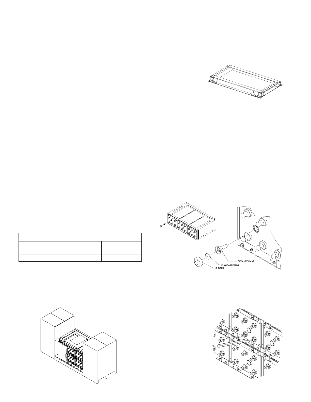
1. Remove floor-mounting base support from the top
of the modules. Base is bolted to module assembly,
upside down.
2. Position base(s),
consult included
layout diagram
for required
configuration.
Bases are required
to be level prior to
installing modules.
3. Anchor holes can be marked and drilled with bases in
place. All anchor holes in base (16 per base) are required
to be used to meet seismic requirements. Consult local
uilding codes for anchor olt requirements. Anchor
olts not included.
4. Cell must be removed from modules prior to installing
modules to base
a. Batteries develop internal pressure. Relieving this
pressure from the cell will make it easier to remove the
cell / sleeve assemblies from the modules.
1. Pry off vent shroud
2. Remove flame arrestor
3. Unscrew valve with 17mm hex key (pressure will
release)
4. Reinstall valve immediately and torque to 12-14 in
lb with 17mm hex key.
5. Cell / sleeve assembly removal from module
a. Thread polypropylene rope through two terminals and
knot.
b. Remove 3/8-16 x 1 1/4 bolts and lock washers from
sleeve.
c. Use an insulated
prybar to loosen
the center cell /
sleeve from the
module. Place the
prybar into the
cutout behind
the retainer.
4
Bolt Size Torque
1/2-13 100 ft-lb 135.5 Nm
3/8-16 25ft-lb 33.8 Nm
1/4-20 125 in-lb 14.1Nm

d. Position lifting device under cell to be removed.
Warning: Care should e taken not to have lifting
device come in contact with cells /sleeve assem lies.
e. Slide sleeve and cell across cell lifting device. It is
recommended that you use two pieces of 2" x 4" or
equivalent lumber to remove cell. (Care should e
taken as not to damage front flange).
f. Cells / sleeve assemblies should be stored
in horizontal position.
6. Remove hardware holding modules together and holding
modules to skid. Hardware removed from modules will
be reused to attach modules to bases and to each other.
Hardware holding modules to skid will not be reused.
CAUTION: Never lift more than one module at a time with
the supplied lifting slings.
7. Install modules onto bases using supplied lifting straps.
Consult below diagram for proper sling attachment
and lifting. Consult included layout diagram for module
position.
8. Module layout should be compared to system layout
diagram and all hardware should be checked for proper
torque before proceeding. Consult “Hardware Torque
Requirements” (pg 4) for proper torque values.
9. For multiple stack systems... oining plates are to be
placed at the rear of the modules at the top of the stacks.
One joining plate is to be used at the junction of two
modules. Use 1/2-13 x 1.50" hardware to install the
plates. Hardware should be torqued after module installa-
tion is complete. Consult “Hardware Torque
Requirements” (pg 4) for proper torque values.
Cell Installation
1. Install cells into modules. Consult layout drawing for
cell location and polarity. Attach cell to module using (4)
3/8-16 x 1.25"hardware*. Consult “Hardware Torque
Requirements” (pg 4) for proper torque values. Care
should e taken when installing cells that lifting device
does not damage rackets.
5

2. Safety Shield Brackets are to be installed at the outside
corners of every 2 modules starting from the bottom and
working towards the top. Use 3/8-16 x 1.25"hardware to
install brackets. Consult “Hardware Torque
Requirements” (pg 4) for proper torque values.
3. Module layout should be compared to system layout
diagram and all hardware should be checked for proper
torque before proceeding. Consult “Hardware Torque
Requirements” (pg 4) for proper torque values.
ELECTRICAL CONNECTION
Connector Assembly
1. The contact surfaces of each individual post on every
cell have been cleaned and coated with a thin film of
no-ox-ID “A” grease at the factory. Assure the contact
surfaces are free of dust or dirt prior to assembly.
2. The battery system is supplied with a connector
package appropriate to the required load the batteries
are connected to. Review the below chart “Connector
Packages” to ensure the correct connector package has
been supplied.
3. Installation and direction of the battery post hardware is
important. Consult the below diagram for clarification.
4. High Rate applications will require multiple connectors to
be used per battery post. A 2CU connector package will
require 2 connectors per connection (1 per side), see
example below. A 4CU package will require 4 connectors
per connection (2 per side) and an 6CU package will
require 6 connectors per connection (3 per side). Tighten
& torque all bolts after all connectors are installed.
Consult “Hardware Torque Requirements” (pg 4) for
proper torque values.
2CU Package Detail
Tier to Tier
Stack to Stack / Cell to Cell
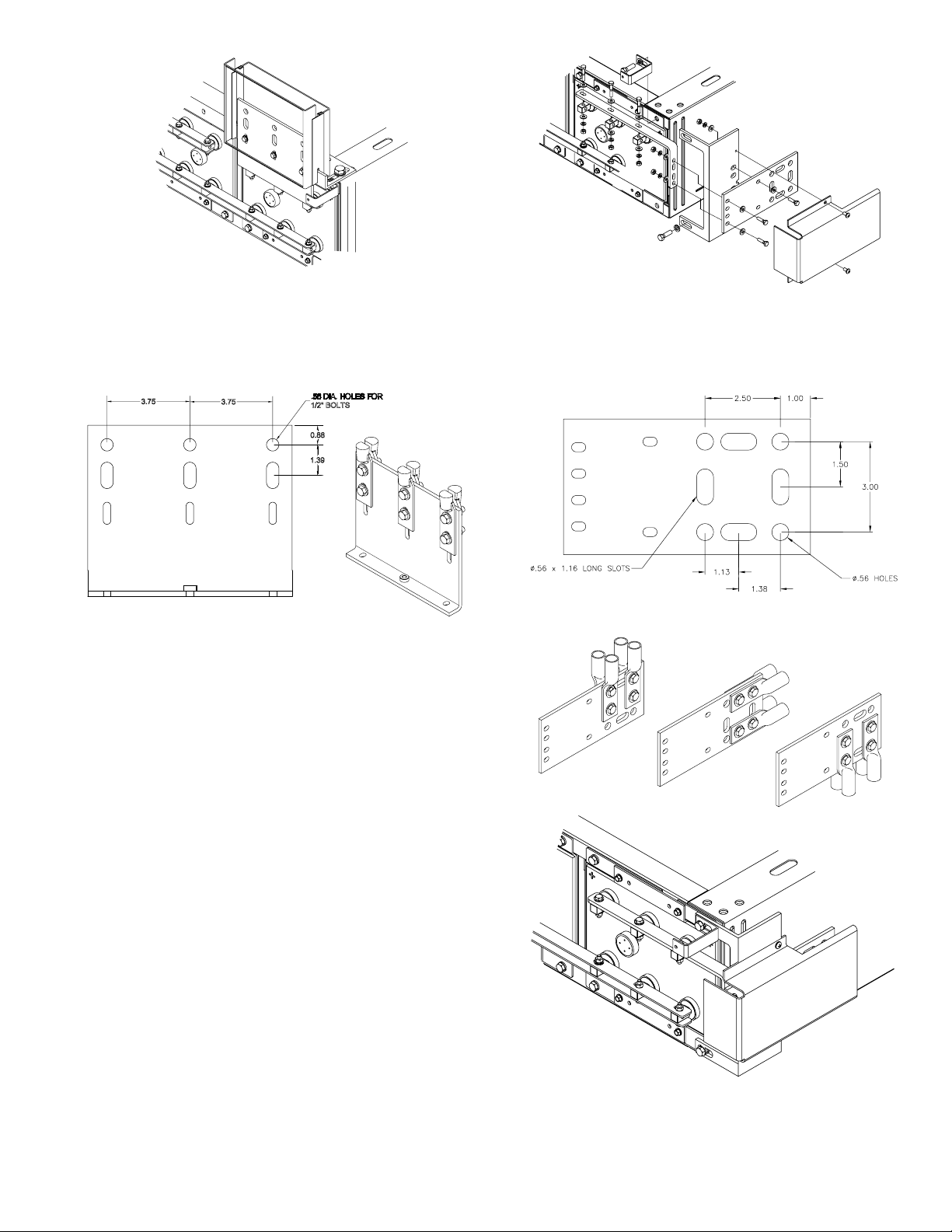
Terminal Assembly
!!!
Consult layout diagram for termination location.
1. Install terminal plate bracket to the top of the module.
Use 1/2-13 x 1.50"hardware. Install loosely for future
alignment.
2. Remove cell sleeve bolts directly behind location of
terminal plate.
3. Replace flat washer with cap washer. Re-install 3/8-16 x
1.25"into cell sleeve with safety shield bracket (if
required). Torque hardware at 25ft-lb (33.8Nm). Install
rubber caps over bolts.
4. Install terminal plate to battery posts using 1/4-20 x
1.75"hardware. Attach terminal plate to terminal plate
bracket. Note position of terminal plate. Terminal Plate
Bracket may have to be moved in order to be flush with
the terminal plate.
5. Consult “Hardware Torque Requirements” (pg 4) for
proper torque values.
Terminal Plate to be installed on battery posts as shown
6
Bolt Package
2CU 1/4-20 x 1.50" MP1407
4CU 1/4-20 x 1.75" MP1435
6CU 1/4-20 x 2.00" MP1409
Connector Packages
Type AMPS WPC
2CU ≤700 ≤1200
4CU ≤2000 ≤3200
6CU ≤3000 ≤4800
7
Complete Assembly
6. Top terminal plate designed to use up to 0.50"dia. bolt
and a maximum 1.75"centers, 2 hole lug. Lug hardware
not included.
Hole Layo t
!!
Consult layout diagram for termination location.
1. Remove cell sleeve bolts (3/8-16 x 1.25") from the
module (retain for later use).
2. Install plastic Side Terminal Bracket in location where
bolts were removed in previous step. Use 3/8-16 x 1.25"
bolts from Step 1. Bolts should be installed loosely for
future adjustments.
3. Safety Shield Bracket may also be required to be
installed. They are to be installed in front of the side
terminal bracket.
4. Install side terminal plate to side terminal bracket
using 1/4-20 x 1.00"hardware. Bolts should be installed
loosely for future adjustments.
5. Install side terminal connectors to battery posts using
1/4-20 bolts. Bolts should be installed loosely for future
adjustments.
6. Connect side terminal plate to side terminal connectors.
Side terminal bracket and side terminal connectors may
have to be adjusted to insure plate and connectors are
flush. Use 1/4-20 x 1.25"hardware.
7. After all parts are installed and alignment is confirmed,
torque all bolts. Consult “Hardware Torque
Requirements” (pg 4) for proper torque values.
8. Install Side Terminal Shield to Side Terminal Bracket
using 1/4-20 screws.
Tighten ut do not torque hardware.
9. Side Terminal Plate is designed to use up to 0.50"dia.
bolt and a maximum 1.75"centers, 2 hole lug. Plate is
capable of handling 4 runs of cable.
L g Positioning Options:
Complete Assembly
Side Terminal Assembly

Final Assembly Check Procedure
1. For future identification of all cells, number individual
cells in sequence, beginning with number one (1) at the
positive end of the battery. The last cell of the
battery is located at the negative output terminal.
2. Read and record the voltages of the individual cells
to assure that they are connected properly. The total bat-
tery voltage should be approximately equal to the num-
ber of cells connected in series multiplied by the meas-
ured voltage of one cell. If the measurement is less,
recheck the connections for proper polarity. Verify that
all cell and battery connections have been properly
torqued.
3. Measure and record the intercell connection resistance
using a micro-ohms meter. This helps determine the
adequacy of initial connections and can be used as a ref-
erence for future maintenance requirements.Refer to the
recording forms in Appendix A of this manual. Review
the records of each connection and detail resistance
measurements. Clean, remake, and remeasure any con-
nection that has a resistance
measurement greater than 10% of the average of all the
same type connections (i.e. intercell, intermodule, etc.).
4. Battery performance is based on the output at the
battery terminals. Therefore, the shortest electrical
connection between the battery system and the
operating equipment results in maximum total
system performance.
Select ca le size ased on current carrying capa ility and
voltage drop.
Cable size should not provide a greater voltage drop
between the battery system and operating equipment than
specified. Excessive voltage drop in cables will reduce the
desired reserve time and power from the battery system.
Safety Shield Assembly
1. All Safety Shield Brackets should already be installed at
this time. Refer to Cell Installation Section for bracket
installation.
2. Safety Shields are designed with a “keyhole” type
attachment
3 One shield will cover two modules. Hang the first shield
on the top brackets through the large part of the keyhole.
At the same time aligning the cutout at the bottom of the
shield with the second set of brackets. After all shields
are in place tighten, but do not torque hardware.
Top Protection Shield Installation
For side terminal assembly, attach top protective cover
to highest front shield.
For top terminal assembly, cut protective cover to fit
between the terminals and then attach to front shield.
SYSTEM OPERATIONS
Char er Volta e
These batteries are designed for continuous float applica-
tions. When setting the float voltage on the charger, the
system should be set to float at the nominal cell float voltage
times the number of cells per string. The charger must be
able to maintain the system voltage within ± 0.5% of the
desired level at all times. The desired float voltage varies
with temperature according to the table in the next column.
Top
Bottom
8

Operatin Temperatures
Battery Temperature Float Voltage per Cell
°F °C ± .01 volts
50˚ 10˚ 2.25
59˚ 15˚ 2.25
68˚ 20˚ 2.25
77˚ 25˚ 2.25
86˚ 30˚ 2.25
95˚ 35˚ 2.23
Operating at temperatures greater than 77ºF (25ºC) will
reduce the operating life of the battery. If operating tempera-
tures are expected to be in excess of 95ºF (35ºC), contact
East Penn for recommendations.
Cell Volta e
Although the charger must maintain the system voltage
within ± 0.5%, individual cell voltages may vary by ± 0.05
volts of the average cell float voltage.
Rectifier Ripple Volta e
Acceptable charging ripple (peak to peak) shall be less than
0.5% of the manufacturer’s recommended string float volt-
age or have a duration shorter than 8 milliseconds.
RECORD KEEPING
Volta es, Temperatures & Ohmic
Readin s
Record keeping is an important part of stationary battery
maintenance and warranty coverage. This information will
help in establishing a life history of the battery and inform
the user if and when corrective action needs to be taken.
(Refer to Appendix A, Battery Maintenance Report)
While it is acceptable to operate at temperatures less than
77ºF (25ºC), it will require longer charging time to become
fully recharged. Also, the capacity will be less at operating
temperatures below 77ºF (25ºC).
After installation and when the batteries have been on float
charge for one week, the following data should be recorded:
1. Battery terminal voltage.
2. Charger voltage.
3. Individual cell float voltages.
4. Ambient temperatures.
5. Terminal connections should be checked to verify that
the installer did torque all connections properly, consult
“Hardware Torque Requirements” (pg 4) for proper
torque values. Micro-ohm readings should be taken
across every connection. Refer to meter manufacturer’s
instructions for proper placement of probes. If any
reading differs by more than 20% from its initial installa-
tion value, re-torque the connection, consult “Hardware
Torque Requirements” (pg 4) for proper torque values. If
reading remains high, clean contact surfaces accord-
ing to Step 1 under Connector Assem ly.
6. Individual cell ohmic readings. For 6-post cells, measure
from center positive to center negative posts. Do not
measure diagonally from positive to negative posts. See
below page for specific location.
MAINTENANCE
Always wear eye protection when working on or near
batteries. Keep sparks and open flames away from batteries
at all times. See Safety Precautions on pg. 3.
Annual Inspection (1)
1. Conduct a visual inspection of each cell.
2. Record the battery string voltage.
3. Record the charger voltage.
4. Record the individual cell voltages. The accuracy of the
DMM (Digital Multimeter) must be .05% (on dc scale)
or better. The DMM must be calibrated to NIST traceable
standards. Because float readings are affected by
discharge and recharges, these readings must be taken
when batteries have been on continuous, uninterrupted
float for at least one month. Cells should be within
± 0.05 volts of the average cell float voltage.
5. Record the ambient temperatures.
6. Record individual cell ohmic readings.
7. Record all interunit and terminal connection resistances.
Micro-ohm readings should be taken during this inspec-
tion. If any reading differs by more than 20% from initial
readings taken, retorque the connection. Recheck the
micro-ohm reading. If the reading remains high, clean
the contact surface according to installation portion of
this manual.
(1)
Other Maintenance Inspection intervals follow IEEE 1188
Rectifier Ripple Volta e
Acceptable charging ripple (peak to peak) shall be less than
0.5% of the manufacturer’s recommended string float
voltage or have a duration shorter than 8 milliseconds.
Battery Cleanin
Batteries, cabinets, racks, and modules should be cleaned
with clear water or a mixture of baking soda and water.
Never se solvents to clean the battery.
measure
point
measure
point
9

Capacity Testin
Capacity tests should not be run unless the battery’s
operation is questionable. Do not discharge the batteries
beyond the specified final voltage. When discharging at
higher rates, extra connectors may need to be added to pre-
vent excessive voltage drop. When performing capacity test-
ing and recording data use IEEE 1188 instructions. Should it
be determined that any individual battery(ies) or cell(s) need
to be replaced, contact your nearest East Penn agent or East
Penn Service Center.
SLEEVE / CELL REMOVAL
PROCEDURE
1. Before removing sleeve / cell, review Safety Precautions
on pg. 3 of this manual. Contact East Penn Mfg.
Company, Inc. with specific questions or concerns.
2. Remove bolts from cell sleeve from battery to be
replaced. Do not remove cell retainer bars and hardware.
3. All tools used to remove cell / sleeve shall be insulated
to avoid contact with battery posts.
4. Lifting device shall be rated to handle weight of cell /
sleeve.
5. Remove one cell / sleeve at a time.
6. A slot is provided behind the steel sleeve to assist in
removing cell / sleeve from module.
7. Refer to Section “Cell Installation” for installing
replacement cell.
NC4-2000 125 AH
A id Volumes & Weights
* Data subject to change.
MSDS sheets can be obtained at www.eastpennunigy.com.
Cell Electrolyte Pure Acid
Size cc gal gm l l
AVR125-33 25,793 6.81 33,531 73.92 29.55
10

)0%5.6%1()'200)1(%7-216 $$$$$$$$$$$$$$$$$$$$$$$$$$$$$$$$$$$$$$$$$$$$$$$$$$$$$$$$$$$$$$$$$$$$$$$$$$$$$$$$$$$$$$$$$$$$$$$$$$$$$$$$
$$$$$$$$$$$$$$$$$$$$$$$$$$$$$$$$$$$$$$$$$$$$$$$$$$$$$$$$$$$$$$$$$$$$$$$$$$$$$$$$$$$$$$$$$$$$$$$$$$$$$$$$$$$$$$$$$$$$$$$$$$$$$$$$$$$$
$$$$$$$$$$$$$$$$$$$$$$$$$$$$$$$$$$$$$$$$$$$$$$$$$$$$$$$$$$$$$$$$$$$$$$$$$$$$$$$$$$$$$$$$$$$$$$$$$$$$$$$$$$$$$$$$$$$$$$$$$$$$$$$$$$$$
)%(-1+6!%.)1; $$$$$$$$$$$$$$$$$$$$$$$$$$$$$$$$$$$$$$$$$$$$$$$$$$$$$$$$$$$$$$$$$$$$$$$$$$$$$$$$$$$$$$$$$$$$$$$$$$$$$$$$$$$$$$$$$$
($',0*44+16.'%(5$-(0$5,045$..$5,10$0'$5.($45$006$..95+(3($)5(3
15$5,10 +,4)13//645%(&1/2.(5('$0'46%/,55('8,5+$09231'6&58$33$059&.$,/
Cell Serial
No. No. Volts
1
2
3
4
5
6
7
8
9
10
11
12
13
14
15
16
17
18
19
20
#
%7) $$$$$$$$$$$$$$$$$$$$$$
203%1; $$$$$$$$$$$$$$$$$$$$$$$$$$$$$$$$$$$$$$$$$$$$$$$$$$$$$$$$$$$$$$$$$$$$$$$$$$$$$$$$$$$$$$$$$$$$
((5)66$$$$$$$$$$$$$$$$$$$$$$$$$$$$$$$$$$$$$$$$$$$$$$$$$$$$$$$$$$$$$$$$$$$$$$$$$$$$$$$$$$$$$$$$$$$$$$
%77)5;2'%7-21%1(2580&)5 $$$$$$$$$$$$$$$$$$$$$$$$$$$$$$$$$$$$$$$$$$$$$$$$$$$$$$$$$$$$$$$$$$$$$$$$$$$$
22*)//6$$$$$$$$!;3)$$$$$$$$$$$$$$$$$$$$$$$$$$$$$$$$%7)*+$$$$$$$$$$$$%7)167%//)($$$$$$$$$$$$
,%5+)587387$$$$$$$$$$$$$$$$$$$$$$$$$$ 0&-)17-5!)03)5%785) $$$$$$$$$$$$$$$$$$$$$$<
!27%/%77)5;#2/7%+)$$$$$$$$$$$$$$$$$%1)/)7)5#2/76$$$$$$$$$$$$$$$$$$$167%//)5$$$$$$$$$$$$$$$$$$$$$$$$$$$$$$$$$$$$$$$$$$$$$$$$$$$
"
Cell Serial
No. No. Volts
21
22
23
24
25
26
27
28
29
30
31
32
33
34
35
36
37
38
39
40
Cell Serial
No. No. Volts
41
42
43
44
45
46
47
48
49
50
51
52
53
54
55
56
57
58
59
60
Connector
Ohmic
Value
Cell
Ohmic
Value
Connector
Ohmic
Value
Cell
Ohmic
Value
Connector
Ohmic
Value
Cell
Ohmic
Value
11

Lyon Station, PA 19536-0147 • Phone: 610-682-6361 • Fax: 610-682-4781
3'(3(2$35/(0515.,0(
:::)%673)1181-+;'20=0%-/6%/)6)%673)1181-+;'20
E.P.M. Form No. 0395 Rev. 2/11 © 2011 by EPM Printed in U.S.A. No part of this document may be copied or reproduced, electronically
or mechanically, without written permission from the company.
:#
“POWERED FOR PERFORMANCE”®
Other manuals for Unigy II
2
Table of contents
Other Deka Camera Accessories manuals

Deka
Deka Unigy II User manual

Deka
Deka EZ LINK D35 User manual

Deka
Deka unigy User manual

Deka
Deka FastCharge F35 User manual

Deka
Deka Dominator Gel-Mate SVRLA G45 User manual

Deka
Deka Unigy II AVR45 Series User manual

Deka
Deka 8A User manual

Deka
Deka unigy I User manual

Deka
Deka SOLAR Monoblock VRLA System Installation instructions

Deka
Deka unigy II SPACESAVER Non-Interlock AVR 45 AH User manual


