Deka Unigy II User manual

Installation and Operation Manual
SECTION I
Safety Precautions
Protective Equipment ..........2
Procedures ..........................2
SECTION II
Receiving & Storage
Receiving Inspection............2
Unpacking............................2
Storage ................................3
SECTION III
Installation
Electric Code for
Maintenance Access............3
Floor Anchoring &
Module Arrangements..........3
Module Installations ............3
SECTION IV
Electrical Connection
Connector Assembly............4
Terminal Assembly ..............4
Final Assembly
Check Procedure ..............4-5
TABLE OF CONTENTS
®
FLUSH EYES
IMMEDIATELY
WITH WATER.
GET
MEDICAL
HELP
FAST.
SULFURIC ACID
CAN CAUSE
BLINDNESS OR
SEVERE BURNS.
NO
•SPARKS
•FLAMES
•SMOKING
SHIELD
EYES.
EXPLOSIVE GASES
CAN CAUSE BLIND-
NESS OR INJURY.
HIGH
VOLTAGE...
RISK OF SHOCK.
DO NOT TOUCH
UNINSULATED
TERMINALS OR
CONNECTORS.
KEEP VENT CAPS TIGHTLY IN PLACE. VENTILATE WELL WHEN IN AN ENCLOSED
SPACE AND WHEN CHARGING.
SEE INSTALLATION, MAINTENANCE AND OPERATION
INSTRUCTIONS FOR IMPORTANT SAFETY PRECAUTIONS.
REPAIR SHOULD BE PERFORMED ONLY
BY A QUALIFIED SERVICE TECHNICIAN.
DANGER
Required by
California
Proposition 65
BATTERIES
AND RELATED PARTS
CONTAIN LEAD
California Proposition 65 Workplace Warning Sign 1/99
Must be posted in workplace near batteries.
WASH HANDS
AFTER HANDLING !
WARNING: Battery posts, terminals and related accessories
contain lead and lead compounds, chemicals known to the
State of California to cause cancer and reproductive harm.
WARNING: Battery posts, terminals and related accessories
contain lead and lead compounds, chemicals known to the
state of California to cause cancer and birth defects or other
reproductive harm. Wash hands after handling.
SECTION IV (cont.)
Electrical Connection (cont.)
Parallel Strings ....................5
Module Front Shield
Assembly ............................6
Terminal Plate Shield
Assembly ............................6
Module Top Shield
Assembly ............................6
SECTION V
System Operations
Float Voltages ......................6
Operating Temperatures ....6
Equalizing ............................6
SECTION VI
Record Keeping
Voltages, Temperatures
& Micro-ohm Readings ....6-7
SECTION VII
Maintenance
Annual Inspection ................7
Battery Cleaning..................7
Capacity Testing ..................7
SECTION VIII
Cell Removal
Procedure ............................7
FIGURES............................8-12
APPENDIX A
Relay Rack
Assembly ......................13-14
APPENDIX B
Material Safety
Data Sheet ....................15-16
APPENDIX C
Battery Maintenance
Report..................................17
APPENDIX D
Technical
Information ....................18-20

SAFETY PRECAUTIONS
Although all valve-regulated batteries have the elec-
trolyte immobilized within the cell, the electrical hazard
associated with batteries still exists. Work performed
on these batteries should be done with the tools
and the protective equipment listed below. Valve-
regulated battery installations should be supervised by
personnel familiar with batteries and battery safety
precautions.
Protective Equipment
To assure safe battery handling, installation and main-
tenance, the following protective equipment should be
used.
1. Safety glasses or face shield
2. Acid-resistant gloves
3. Protective aprons
4. Proper lifting devices
5. Tools with insulated handles
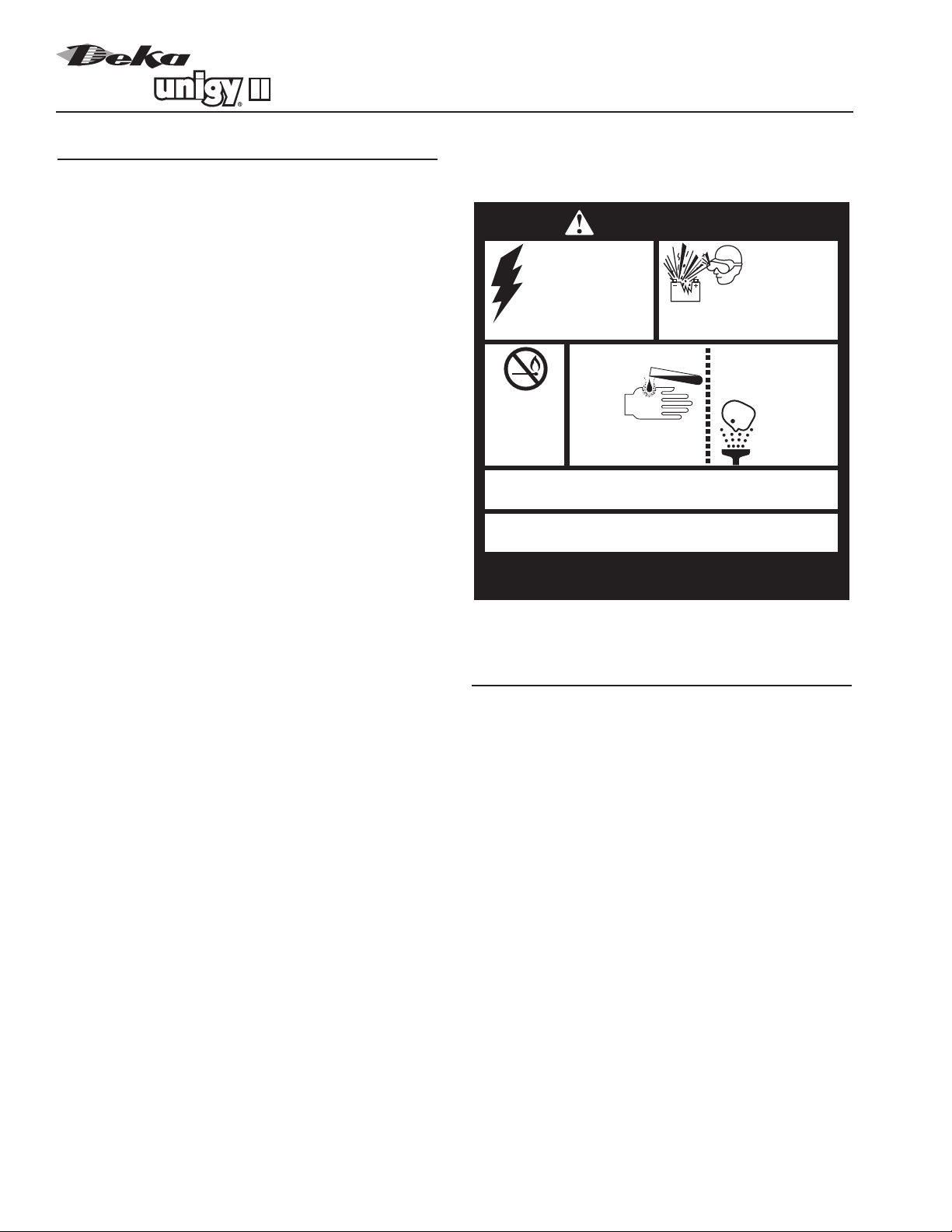
Procedures
(Always wear safety glasses or face shield when
working on or near batteries. Refer to Fig. 1-1 on
pg. 2.)
The following safety procedures should be followed
during installation:
1.These batteries are sealed and contain no free
electrolyte. Under normal operating conditions, they
do not present any acid danger. However, if the
battery jar or cover is damaged, acid could be
present. Sulfuric acid is harmful to the skin and
eyes. Flush affected area with water immedi-
ately and consult a physician if splashed in the
eyes.
2. Prohibit smoking and open flames, and avoid
arcing in the immediate vicinity of the battery.
3. Do not wear metallic objects, such as jewelry,
while working on batteries.
4. Keep the top of the battery dry and clear of tools
and other foreign objects.
5. Provide adequate ventilation and follow recom-
mended charging voltages.
6. Refer to Material Safety Data Sheet for proper extin-
guishing mehod (See Appendix B, Sect. 4, pg 15.).
7. Never remove or tamper with the pressure relief
valves.Warranty void if vent valve is removed.
8. Inspect all flooring and lifting equipment for func-
tional adequacy. Specifically review floor-loading
capacity.
9. Adequately secure battery modules to the floor.
10. Connect support structures to ground system in
accordance with applicable codes.
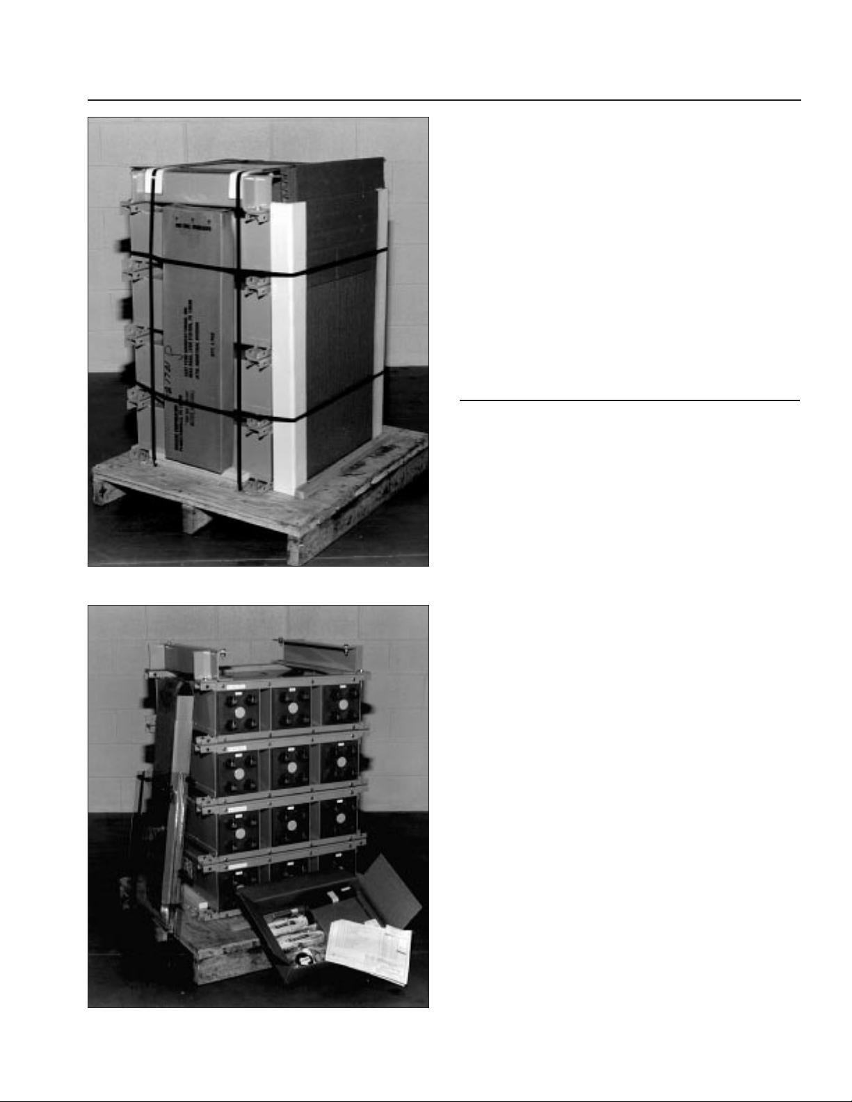
RECEIVING & STORAGE
Receiving Inspection
Upon receipt of the battery and at the time of unload-
ing, each package should be visually inspected for
damage. If damage is evident, a more detailed inspec-
tion of the entire shipment should be conducted and
noted on the bill of lading. Record receipt date and
inspection data, and notify the carrier of any damage.
Unpacking
1. Always wear eye protection.
2. Check for visible defects.
3. Check the contents of the package against the
packing list. Report any missing parts or shipping
damage to your East Penn agent or East Penn Mfg.
Co. immediately. (See Fig. 2-1 and 2-2 on pg. 3.)
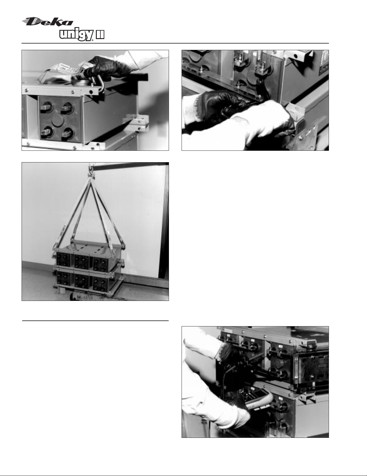
4. Never lift the batteries by the terminal posts. Always
lift batteries by the module mounting holes with the
lifting straps provided. (See Fig. 3-2, pg. 8.)
5.When lifting batteries, the proper equipment is
needed such as a forklift or a portable crane.
Always check the lifting capacities of the equipment
being used and never lift more than one module at
a time by the module mounting holes.
®
2
DANGER
SHIELD
EYES.
EXPLOSIVE
GASES CAN CAUSE
BLINDNESS OR INJURY.
HIGH VOLTAGE...
RISK OF SHOCK.
DO NOT TOUCH
UNINSULATED
TERMINALS OR
CONNECTORS.
VENTILATE WELL WHEN IN AN ENCLOSED
SPACE AND WHEN CHARGING.
SEE INSTALLATION, MAINTENANCE AND OPERATION
INSTRUCTIONS FOR IMPORTANT SAFETY PRECAUTIONS.
NO
•SPARKS
•FLAMES
•SMOKING
SULFURIC
ACID
CAN
CAUSE
BLINDNESS OR
SEVERE BURNS.
FLUSH EYES
IMMEDIATELY
WITH WATER.
GET
MEDICAL
HELP
FAST.
DO NOT REMOVE VENT VALVE.
WARRANTY VOID IF VENT VALVE IS REMOVED.
Fig. 1-1

Storage
1. Cells should be stored indoors in a clean, level, dry,
cool location. Recommended storage temperatures
are 0˚F to 90˚F (–18˚C to 32˚C). Store in a horizon-
tal position only.
2. Stored lead-acid batteries self discharge and must
be given a boost charge six months from the date
of manufacture to prevent permanent performance
degradation. Batteries should not be stored for more
than 180 days without applying a boost charge of
2.30 VPC ± 1% for a maximum of 24 hours. Record
dates and conditions for all charges during storage.
INSTALLATION
Electric Code for Maintenance Access
Refer to ANSI/NFPA-70 National Electric Code for
access and working space requirements around the
battery. A minimum of 36" aisle space is recom-
mended in front of the battery for service and inspec-
tion.
Floor Anchoring & Module Arrangements
See East Penn Mfg. Co.’s schematic diagram illustra-
tion. One is supplied with each shipment. If it cannot
be located, contact East Penn Mfg. Co. for a copy.
Refer to your delivery number, located on the packing
slip.This will aid in obtaining the proper drawing.
Module Installations
Assemble modules per the following details.
NOTE: Batteries are typically packaged in the reverse
order for easy installation: Floor channels are on top,
followed by the bottom most module. (See Fig. 3-1, pg.8.)
CAUTION: Never lift more than one module at a
time with the lifting slings. (See Fig. 3-2, pg. 8.)
1. Unbolt the floor mounting channels from the top of
the battery. Secure mounting channels to the floor.
2. Using the two slings provided, remove the top module
and bolt onto the floor mounting channels. (See Fig.
3-3, pg. 8 on using the proper lifting equipment.)
3. Remove the next module and bolt onto the first
module. Repeat this procedure until the battery is
installed to the specified configuration. (See Fig. 3-4
and 3-5, pg. 4.)
Each battery is shipped with its own schematic. Make
sure the polarization on the batteries matches the
drawings.
3
Fig. 2-1
Fig. 2-2

ELECTRICAL CONNECTION
Connector Assembly
1.The contact surfaces of each individual post on
every cell have been cleaned and coated with a thin
film of no-ox ID “A” grease at the factory.
2.The intercell connector contact surfaces should be
cleaned by rubbing gently with a non-metallic brush
or pad. Apply a thin film of no-ox ID “A” grease
which has been supplied.
3. Install all intercell connectors loosely to allow for
final alignment of batteries, then torque to 100 ± 5
inch-pounds (11.3 ± .5 Nm). (Refer to Fig. 4-1 on
pg. 4.)
4.When more than one intercell connector per battery
terminal is required, place the connectors on each
side of the terminal. (See Fig. 4-2, pg. 9.)
Terminal Assembly
1. Attach the terminal mounting bracket to the module
frame. (Side terminal–see Fig. 4-3, pg. 9, top termi-
nal–see Fig. 4-4 and 4-5, pg. 10.)
2. Attach the terminal plates to the battery posts and
then to the mounting bracket.
3. For cable connection assembly, see Fig. 4-6, pg. 11.
Final Assembly Check Procedure
1. For future identification of all cells, number individ-
ual cells in sequence, beginning with number one
at the positive end of the first battery.
2. After torquing the electrical connections on assem-
bled modules, read the voltages of the battery to
assure that the individual cells are connected
correctly. (See Fig. 4-7 on pg 4.) The total voltage
should be approximately equal to the number of
cells times the measured voltage of one cell. If the
measurement is less, recheck the connections for
proper polarity.
®
4
Fig. 3-4
Fig. 3-5
Fig. 4-1
Fig. 4-7

3. Measure and record the intercell connection resis-
tance using a milliohmmeter.This helps determine
the adequacy of initial installation and can be used
as a reference for future maintenance requirements.
Refer to the recording forms in Appendix C of this
manual. Review the records of each connection and
detail resistance measurements. Clean, remake, and
remeasure any connection that has a resistance
measurement greater than 10% of the average of
all the same type connections (intercell, intermodule).
4. Battery performance is based on the output at the
battery terminals.Therefore, the shortest electrical
connection between the battery system and the
operating equipment results in maximum total
system performance.
Select cable size based on current carrying
capability and voltage drop.
Cable size should not provide a greater voltage drop
between the battery system and operating equipment
than specified. Excess voltage drop will reduce the
desired support of the battery system.
Parallel Strings
When paralleling valve-regulated batteries, the capacity,
arrangement, and external circuit length should be
identical for each battery.Wide variation in the battery
circuit resistance can result in unbalanced charging
(i.e., excessive charging currents in some batteries
and undercharging in others). As a result, cell failures
in one battery string and subsequent loss of perfor-
mance capabilities of that string will result in higher
loads in the other parallel string(s), which may exceed
the ratings of the battery connections. This can
damage the battery system and dramatically shorten
battery life.
5
Fig. 4-9
Fig. 4-10
Fig. 4-12
Fig. 4-14

Module Front Shield Assembly
1. Remove clear protective covering from the shields.
2. Attach the standoff through the shield and fasten
the nuts. (See Fig. 4-9 on pg. 5 and 4-8 on pg. 11.)
NOTE: Use the long standoff for the four corners
and the short standoffs for the center holes.
3. Insert the fully assembled shield through the holes in
the battery module until the standoff locks in place.
(See Fig. 4-8 on pg. 11, and 4-10 on pg. 5.)
Terminal Plate Shield Assembly
1. For side terminal shield assembly, refer to Fig. 4-3
on pg. 9 and 4-12 on pg. 5.
1. For top terminal shield assembly, refer to Fig. 4-4
on pg. 10 and 4-14 on pg. 5.
Module Top Shield Assembly
1. For side terminal assembly, attach the top shield to
the highest front shield. (Refer to Fig. 4-11 on pg. 12
and 4-12 on pg. 5.)
2. For top terminal assembly, cut the top shield to fit
between the terminal shields and attach it to the face
shield. (See Fig. 4-13 on pg. 12 and 4-14 on pg. 5.)
SYSTEM OPERATIONS
Float Voltages
These batteries are designed for 20-year life when
floated at 2.25 ± 1% volts per cell (VPC) at 77˚F
(25˚C) or less.The charger must be able to sustain the
system voltage within ± 1% of the desired level at all
times.The desired float voltage varies with the temper-
ature according to the table below.
Operating Temperatures
Temperature Temperature Per Cell Float
Degrees F Degrees C Voltage ± 1%
50˚ 10˚ 2.25
59˚ 15˚ 2.25
68˚ 20˚ 2.25
77˚ 25˚ 2.25
86˚ 30˚ 2.25
95˚ 35˚ 2.23
Equalizing
Upon installation of the battery, an optional boost
charge of 2.30 VPC ± 1% for a maximum of 24 hours
can be applied. If this is done, be sure to reset the
charging equipment to the proper float voltage.The
average battery operating temperature should not
exceed 95˚F (35˚C) and never exceed 105˚F (40.5˚C)
for more than an eight-hour period.
Operating at temperatures greater than 77˚F (25˚C)
will reduce the operating life of the battery. If operating
temperatures are expected to remain in excess of
95˚F (35˚C), contact East Penn for recommendations.
RECORD KEEPING
Voltages,Temperatures & Micro-Ohm
Readings
Record keeping is an important part of stationary
battery maintenance.This information will help in
establishing a life history of the battery and inform the
user if and when corrective action needs to be taken.
(Refer to Appendix C.)
While it is acceptable to operate at temperatures less
than 77˚F (25˚C), it will require longer charging time to
become fully recharged. Also the capacity will be less
at operating temperatures below 77˚F (25˚C). (See
pg. 17.)
After installation and when the batteries are on float
charge for one week, the following data should be
recorded on the sticker located closest to the positive
terminal.
1. Battery terminal voltage
2. Charger voltage
3. Individual cell voltages
4. Ambient temperatures
5.Terminal connection should be checked to verify that
the installer did torque all connections properly (100
± 5 in.-lbs.).
®
6
Fig. 6-2

6. Micro-ohm readings should be taken across every
connection. (Refer to Fig. 6-2, pg. 6.) If any reading
differs by more than 20%, retorque the connection
to 100 ± 5 inch-pounds. If the reading remains high,
clean contact surfaces according to Step 2 under
Connector Assembly.
MAINTENANCE
Always wear eye protection when working on or near
batteries. Keep sparks and open flames away from
batteries at all times.
Annual Inspection
1. Conduct a visual inspection of the battery.
2. Check the battery terminal voltage.
3. Check the charger voltage.
4. Check the individual cell voltages. Cells should be
within ± .05 volts of float voltage.
5. Check the ambient temperatures.
6. Check all interunit and terminal connections. Micro-
ohm readings should be taken during this inspec-
tion. If any reading differs by more than 20% from
the initial reading taken, retorque the connection to
100 ± 5 inch-pounds. Recheck the micro-ohm read-
ing. If the reading remains high, clean the contact
surfaces according to Step 2 under Connector
Assembly.
Battery Cleaning
Battery modules and covers should be cleaned with
clear water or a mixture of baking soda and water.
Never use solvents to clean the battery.
Capacity Testing
Capacity tests should not be run unless the batteries
operation is questionable. Do not discharge the batter-
ies beyond the specified final voltage. Record all find-
ings.
Should it be determined that any individual cell(s)
need to be replaced, contact your nearest Unigy II
Agent or East Penn Service Center.
CELL REMOVAL PROCEDURE
1. Before removing cells, review safety procedures
on page 2 of this manual. Contact East Penn
Manufacturing Company, Inc. with specific questions
or concerns.
2. Refer to Fig. 8-1 through 8-4 (pg. 7) for specific
instructions.
7
Fig. 8-1
Fig. 8-2
Fig. 8-3
Fig. 8-4

®
8
Fig. 3-1
Fig. 3-2
Fig. 3-3
“”

9
Fig. 4-2
Fig. 4-3

®
10
Fig. 4-4
Fig. 4-5

11
Fig. 4-6
Fig. 4-8

®
12
Fig. 4-11
Fig. 4-13

13
Fig. A-1
Fig. A-2
APPENDIX A
Relay Rack Assembly
1. Attach the floor mounting brackets to the frame
upright. (Refer to Fig. A-1, pg. 13 for relay rack
assembly.)
NOTE: If installing battery without relay rack,
follow standard module instructions for battery
assembly. (Refer to Fig. A-2, pg. 13) for assembly
instructions.)
2. Insert module base support between the frame
uprights (level and anchor). Anchor bolts are not
included.
3. Using the lifting slings provided, remove the top
module from the shipping pallet and bolt it to the
module base support. (Refer to Fig. A-3 on pg. 14,
Steps 1 and 2.)
CAUTION: Never lift more than one module at
a time with the lifting slings.
4. Remove the next module and bolt it to the first
module. Repeat this procedure until the battery is
installed to its proper configuration. (Refer to Fig.
A-3 on pg.14, Steps 3 and 4.)
NOTE: Use the schematic supplied with the battery.
5. Insert the stabilizing bracket and bolt it to the top
module. (See Fig. A-4, pg 14, for instructions.)
1

®
14
Fig. A-3
Fig. A-4
APPENDIX A

– Material Safety Data Sheet –
UNIGY II – VALVE REGULATED LEAD ACID BATTERY –
ABSORBED ELECTROLYTE BATTERY SEALED NON-SPILLABLE
SECTION II
HAZARDOUS INGREDIENTS/IDENTITY INFORMATION
Manufacturer’s Name: East Penn Manufacturing Co., Inc., Deka Road, Lyon Station, PA 19536
Telephone Number for Information: (610) 682-6361 Original Date Prepared: 1/31/92
Emergency Telephone Number: CHEMTREC: 1-800-424-9300 Revision #5 September 1998
In Washington D.C. or ouside continental U.S., call 1-202-483-7616
SECTION III
PHYSICAL/CHEMICAL CHARACTERISTICS
SECTION IV
FIRE AND EXPLOSION HAZARD DATA
Hazardous Components Range Percent
Specific Chemical Identity [Common Name(s)] OSHA PEL ACGIH TLV by Weight Average
Lead, CAS # 7439921 0.05mg/m30.05 mg/m365–75% 70%
Sulfuric Acid, CAS # 7664939 1.00 mg/m31.00 mg/m35–15% 10%
Antimony, CAS # 7440360 0.50 mg/m30.50 mg/m30–0.1% <0.1%
Arsenic, CAS # 7440382 0.01 mg/m30.01 mg/m30–0.1% <0.1%
Polypropylene, CAS # 9003070 N/A N/A 5–12% 8%#
Calcium, CAS # 7440702 1.0 mg/m31.0 mg/m30–0.1% <0.1%
Tin, CAS # 7440702 2.0 mg/m32.0 mg/m30–0.1% <0.1%
Flash Point (Method Used): Non-Flammable Flammable Limits: *Hydrogen Gas
Extinguishing Media: Class ABC extinguisher LEL: 4% UEL: 74%
NOTE: CO2may be used, but not directly on the cell. The thermal shock may cause cracking of the battery case(s).
Electrolyte (Sulfuric Acid):
Appearance and Odor: Clear, odorless, colorless liquid
Boiling Point: 235–240°F
Evaporation Rate (Butyl Acetate=1): Less than 1.0
Melting Point: N/A
SECTION I
SECTION V
REACTIVITY DATA
Stability: Stable Condition to Avoid: Prolonged overcharging, sources of ignition
Incompatibility (Materials to Avoid): Sulfuric Acid: Contact with combustibles and organic materials may cause fire and explosion.
Also reacts violently with strong reducing agents, metals, strong oxidizers and water.
Contact with metals may produce toxic sulfur dioxide fumes and may release flammable
hydrogen gas.
Hazardous Decomposition of By-Products: Sulfuric Acid: Excessive overcharging or fire may create sulfur trioxide, carbon
monoxide, sulfuric acid mist, sulfur dioxide, and hydrogen.
Lead Compounds: Contact with strong acid or base presence of nascent hydrogen
may generate highly toxic arsenic gas. continued
15
®
Solubility in Water: 100%
Specific Gravity (H2O=1): 1.270–1.330
Vapor Density (Air=1): Greater than 1
Vapor Pressure (mm Hg): 10
APPENDIX B

SECTION VI
HEALTH HAZARD DATA
SECTION VII
PRECAUTIONS FOR SAFE HANDLING AND USE
Routes of Entry: Not applicable under normal use.
Carcinogenicity: Sulfuric Acid: The International Agency for Research on Cancer (IARC) has classified “strong inorganic acid mist
containing sulfuric acid” as a Category 1 carcinogen, a substance that is carcinogenic to humans. This classification
does not apply to liquid forms of sulfuric acid contained within a battery. Inorganic acid mist (sulfuric acid mist)
is not generated under normal use of this product. Misuse of the product, such as overcharging, may
result in the generation of sulfuric acid mist.
Lead Compounds: Lead is listed as a 2B carcinogen, likely in animals at extreme doses. Proof of carcinogenicity
in humans is lacking at present.
Arsenic: Listed by National Toxicology Program (NTP), IARC, OSHA, and NIOSH as a carcinogen only after
prolonged exposure at high levels.
Signs and Symptoms of Exposure: Avoid contact. Absorbed electrolyte (sulfuric acid) may cause irritation of eyes,
nose and throat. Contact with eyes and skin causes irritation and skin burns. Absorbed electrolyte is corrosive.
Medical Conditions Generally Aggravated by Exposure: N/A
Health Hazards (Acute and Chronic): Do not open battery, avoid contact with internal components. Internal components include lead
and absorbed sulfuric acid electrolyte. Electrolyte is corrosive and contact may cause skin irritation and chemical burns.
Emergency and First Aid Procedures:
1. Flush contacted area with large amounts of water for at least 15 minutes. Remove contaminated clothing
and obtain medical attention if necessary. Eye wash and/or emergency shower should be readily available.
2. If swallowed, give large volumes of water. DO NOT induce vomiting. Obtain medical treatment.
Steps to be Taken in Case Material is Released or Spilled: Electrolyte material is corrosive. Contains sulfuric acid.
Neutralize any spilled material.
Waste Disposal Method: Lead-acid batteries are completely recyclable. For information on returning batteries to East Penn for
recycling, contact your East Penn representative. Dispose of any collected material in accordance
with local, state or applicable federal regulations.
Precautions to be Taken in Handling and Storing: Store away from reactive material as defined in Section V, Reactivity Data.
Other Precautions: If battery case is broken, avoid direct contact with internal components. Keep away from ignition sources
during charging. DOT Emergency Response Guide #154.
SECTION VIII
CONTROL MEASURES
NFPA Hazard Rating Sulfuric Acid Lead
Health (Blue) 3 3
Flammability (Red) 0 0
Reactivity (Yellow) 2 0
Note: Sulfuric acid is water-reactive if concentrated.
SECTION IX
OTHER REGULATORY INFORMATION
IATA: AVR Series (Unigy II), have successfully completed
the A67 testing requirements applicable with the IATA Dangerous Goods Regulation.
RCRA:Spent lead-acid batteries are not regulated as hazardous waste when recycled. Spilled sulfuric acid is a characteristic
hazardous waste, EPA hazardous waste number D002 (corrosivity).
CERCLA (Superfund) and EPCRA (Emergency Planning and Community Right to Know Act):
a) Reportable quantity (RQ) for spilled 100% sulfuric acid is 1000 lbs.
b) Sulfuric acid is a listed “Extremely Hazardous Substance” under EPCRA with a Threshold Planning Quantity (TPQ) of 1000 lbs.
c) EPCRA Section 312 Tier II reporting required for batteries if sulfuric acid is present in quantities of 500 lbs. or more and/or
lead is present in quantities of 10,000 lbs. or more.
For additional information concerning East Penn Manufacturing Co., Inc. products or
questions concerning the content of this MSDS please contact your East Penn representative.
Respiratory Protection (Specific Type): N/A
Ventilation: Must be provided when charging in an enclosed area.
Protective Gloves: N/A
Eye Protection: Recommended
Other Protective Clothing or Equipment: N/A
Work/Hygienic Practices: Good personal hygiene and
work practices are recommended.
APPENDIX B (continued)
U.S. DOT: Battery Wet, Non-spillable
Hazard Class/Division 8
ID Number UN2800
Packing Group III
Label Requirement Corrosive
16

®
BATTERY MAINTENANCE REPORT Date______________________
Company ____________________________________________________________________________________________
Address______________________________________________________________________________________________
Battery Location and/or Number____________________________________________________________________________
No. of Cells____________________ Type______________ Date New____________ Date Installed________________
Charger Output__________________________ Ambient Air Temperature______________________°F
Total Battery Voltage______________________________ Panel Meter Volts ____________________
INDIVIDUAL CELL READINGS
17
APPENDIX C
Remarks and Recommendations ________________________________________________________________________________________________________
____________________________________________________________________________________________________________________________________
____________________________________________________________________________________________________________________________________
____________________________________________________________________________________________________________________________________
Readings Taken By ____________________________________________________________________________________________________________________
Readings should be taken at installation and annually thereafter.
Cell Serial
No. No. Volts Ohms or Mhos
1
2
3
4
5
6
7
8
9
10
11
12
13
14
15
16
17
18
19
20
Cell Serial
No. No. Volts Ohms or Mhos
21
22
23
24
25
26
27
28
29
30
31
32
33
34
35
36
37
38
39
40
Cell Serial
No. No. Volts Ohms or Mhos
41
42
43
44
45
46
47
48
49
50
51
52
53
54
55
56
57
58
59
60

®
18
APPENDIX D
UNIGY II Discharge Rates in Amperes to 1.75 VPC Final @ 77°F (25°C)
CELL Nom. A.H. Cap. Hours
TYPE (8 Hr. Discharge Rate) 24 12 10 8 6 5 4 3 2 1
45AH
6AVR45-5 90 5 8 10 11 14 16 19 24 32 52
6AVR45-7 140 7 13 14 17 22 25 29 36 47 78
6AVR45-9 185 9 17 19 23 29 33 39 48 63 105
6AVR45-11 230 11 21 24 29 36 41 48 60 79 131
6AVR45-13 275 14 25 29 34 43 49 58 71 95 157
6AVR45-15 320 16 29 34 40 50 58 68 83 110 183
75AH
6AVR75-5 160 8 14 16 20 25 28 33 41 54 87
6AVR75-7 235 12 21 25 29 37 42 50 61 80 130
6AVR75-9 310 16 28 33 39 49 56 66 82 107 174
6AVR75-11 390 20 35 41 49 61 70 83 102 134 217
6AVR75-13 470 23 42 49 59 73 84 100 123 161 261
6AVR75-15 550 27 50 57 69 86 98 116 143 187 304
3AVR75-17 630 31 57 66 79 98 112 133 163 214 347
3AVR75-19 705 35 64 74 88 110 127 150 184 241 390
3AVR75-21 785 39 71 82 98 122 141 166 204 268 434
3AVR75-23 865 43 78 90 108 135 155 183 225 295 478
3AVR75-25 945 47 85 98 118 147 169 200 245 321 521
3AVR75-27 1025 51 92 107 128 159 183 216 265 348 564
3AVR75-29 1100 55 99 115 138 171 197 233 286 375 608
3AVR75-31 1175 59 106 123 147 184 211 250 306 402 651
3AVR75-33 1255 63 113 131 157 196 225 266 327 428 694
85AH
6AVR85-7 265 13 24 27 33 41 47 56 68 90 139
6AVR85-9 350 17 32 37 44 55 63 74 91 119 185
6AVR85-11 440 22 40 46 55 68 78 93 114 149 231
6AVR85-13 530 26 47 55 66 82 94 111 137 179 278
6AVR85-15 615 31 55 64 77 95 110 130 159 209 324
3AVR85-17 695 35 63 73 87 109 125 148 182 239 370
3AVR85-19 785 39 71 82 98 123 141 167 205 268 417
3AVR85-21 875 44 79 91 109 136 157 185 228 298 463
3AVR85-23 960 48 87 100 120 150 172 204 250 328 509
3AVR85-25 1050 52 95 110 131 164 188 222 273 358 555
3AVR85-27 1135 57 103 119 142 177 204 241 296 387 602
3AVR85-29 1225 61 111 128 153 191 219 259 319 417 648
3AVR85-31 1310 65 118 137 164 204 235 278 341 447 694
3AVR85-33 1400 70 126 146 175 218 250 296 364 477 740
1AVR85-39 1585 78 142 164 197 245 282 333 410 536 833
1AVR85-45 1845 92 166 192 230 286 329 389 478 626 972
1AVR85-51 2095 105 189 219 262 327 376 444 546 715 1111
1AVR85-57 2360 118 213 247 295 368 423 500 615 804 1250
1AVR85-63 2625 131 237 274 328 409 470 555 683 894 1388
1AVR85-69 2890 144 260 301 361 449 517 611 751 983 1527
1AVR85-75 3145 157 284 329 393 490 564 666 819 1073 1666
1AVR85-81 3405 170 308 356 426 531 611 722 888 1162 1805
1AVR85-87 3675 183 332 383 459 572 658 777 956 1251 1944
1AVR85-93 3935 196 355 411 492 613 705 833 1024 1341 2083
1AVR85-99 4200 209 379 438 525 654 751 888 1092 1430 2221

19
No. of
Cells No. LH
45 Amps per Positive 75 Amps per Positive 85 Amps per Positive
per Plts. D* Wt. D* Wt. D* Wt.
Module
520.19 8.50 17.50 179 24.50 259 ——
512.8 215.9 444.5 81.19 622.3 117.48
724.62 8.50 17.50 225 24.50 330 27.12 357
625.4 215.9 444.5 102.06 622.3 149.69 688.9 161.94
6929.12 8.50 17.50 271 24.50 397 27.12 439
739.7 215.9 444.5 122.93 622.3 180.08 688.9 199.13
11 33.62 8.50 17.50 317 24.50 471 27.12 521
853.9 215.9 444.5 143.79 622.3 213.65 688.9 236.33
13 38.12 8.50 17.50 362 24.50 542 27.12 603
968.3 215.9 444.5 164.20 622.3 245.85 688.9 273.52
15 42.62 8.56 17.50 408 24.50 612 27.12 682
1082.6 217.5 444.5 185.07 622.3 277.60 688.9 309.36
17 27.62 8.56 —— 24.50 382 27.12 428
701.6 217.5 622.3 173.28 688.9 194.14
19 29.88 8.56 —— 24.50 420 27.12 472
758.9 217.5 622.3 190.51 688.9 214.10
21 32.10 8.56 —— 24.50 458 27.12 508
815.8 217.5 622.3 207.75 688.9 230.43
23 34.38 8.56 —— 24.50 496 27.12 557
873.3 217.5 622.3 224.99 688.9 252.66
325 36.62 8.56 —— 24.50 530 27.12 598
930.2 217.5 622.3 240.41 688.9 271.25
27 38.88 8.56 —— 24.50 568 27.12 639
987.6 217.5 622.3 257.65 688.9 289.85
29 41.12 8.56 —— 24.50 606 27.12 683
1044.5 217.5 622.3 274.88 688.9 309.81
31 43.38 8.56 —— 24.50 634 27.12 724
1101.9 217.5 622.3 287.58 688.9 328.41
33 45.62 8.56 —— 24.50 681 27.12 770
1158.8 217.5 622.3 308.90 688.9 349.27
39 23.12 8.56 27.12 320
587.2 217.5 —— — — 688.9 145.15
45 25.38 8.56 27.12 375
644.7 217.5 —— — — 688.9 170.10
51 27.62 8.56 27.12 428
701.6 217.5 —— — — 688.9 194.14
57 29.88 8.56 27.12 472
758.9 217.5 —— — — 688.9 214.10
63 32.12 8.56 27.12 508
1 815.9 217.5 —— — — 688.9 230.43
69 34.38 8.56 27.12 557
873.3 217.5 —— — — 688.9 252.66
75 36.62 8.56 27.12 598
930.2 217.5 —— — — 688.9 271.25
81 38.88 8.56 27.12 639
987.6 217.5 —— — — 688.9 289.85
87 41.12 8.56 27.12 683
1044.5 217.5 —— — — 688.9 309.81
93 43.38 8.56 27.12 724
1101.9 217.5 —— — — 688.9 328.41
99 45.62 8.56 27.12 770
1158.8 217.5 —— — — 688.9 349.27
Chart contains dimensions in inches over millimeters and weight in pounds over kilograms.
* Over insulation shield.
RETURN
LEAD
RECYCLE
Pb
Module Dimensional Information
48 volt
assembly
with standard
covers.
4.00
“H”
“D”
“L”

APPENDIX D (continued)
®
20
ELECTROLYTE PURE ACID
TYPE CCs GALLONS POUNDS POUNDS
45-5 1395 0.37 4.0 1.56
45-7 1955 0.52 5.6 2.18
45-9 2520 0.67 7.2 2.82
45-11 3080 0.81 8.8 3.44
45-13 3640 0.96 10.4 4.07
45-15 4200 1.11 12.0 4.69
75-5 2295 0.61 6.6 2.56
75-7 3275 0.87 9.4 3.66
75-9 4215 1.11 12.0 4.71
75-11 5150 1.36 14.7 5.76
75-13 6085 1.61 17.4 6.80
75-15 7025 1.86 20.1 7.85
75-17 7960 2.10 22.8 8.90
75-19 8750 2.31 25.0 9.78
75-21 9835 2.60 28.1 10.99
75-23 10770 2.85 30.8 12.04
75-25 11710 3.09 33.5 13.09
75-27 12643 3.34 36.1 14.13
75-29 135580 3.59 38.8 15.18
75-31 14515 3.83 41.5 16.22
75-33 15455 4.08 44.2 17.27
85-7 3685 0.97 10.5 4.12
85-9 4740 1.25 13.5 5.30
85-11 5795 1.53 16.6 6.48
85-13 6855 1.81 19.6 7.66
85-15 7905 2.09 22.6 8.83
85-17 8965 2.37 25.6 10.02
85-19 10025 2.65 28.7 11.20
85-21 11075 2.93 31.7 12.38
85-23 12135 3.21 34.7 13.56
85-25 13180 3.48 37.7 14.73
85-27 14245 3.76 40.7 15.92
85-29 15300 4.04 43.7 17.10
85-31 16360 4.32 46.8 18.28
85-33 17415 4.60 49.8 19.46
Unigy II Acid Volumes & Weights
Lyon Station, PA 19536-0147 • Phone: (610) 682-6361 • Fax: (610) 682-4781
Order Department Hotline: (610) 682-4231
EPM Form No. 0925 Rev. 3/00 ©2000 by EPM Printed in U.S.A.
Other manuals for Unigy II
2
Table of contents
Other Deka Camera Accessories manuals

Deka
Deka SOLAR Monoblock VRLA System Installation instructions

Deka
Deka Unigy I User manual

Deka
Deka EZ LINK D35 User manual

Deka
Deka unigy II SPACESAVER Non-Interlock AVR 45 AH User manual

Deka
Deka 8A User manual

Deka
Deka Dominator Gel-Mate SVRLA G45 User manual

Deka
Deka unigy User manual

Deka
Deka FastCharge F35 User manual

Deka
Deka unigy I User manual

Deka
Deka Dominator Gel-Mate SVRLA G105 User manual