manuals.online logo
Brands
  1. Home
  2. •
  3. Brands
  4. •
  5. Dell
  6. •
  7. Server
  8. •
  9. Dell PowerEdge systems 6300 Service manual

Dell PowerEdge systems 6300 Service manual

Dell PowerEdge 6300 and 4300 Systems 1 x 2 Backplane Installation Information1
'HOO3RZHU(GJHDQG
6\VWHPV[%DFNSODQH
,QVWDOODWLRQ,QIRUPDWLRQ
This document provides installation instructions for the optional 1 x 2 small computer
system interface (SCSI) backplane for the Dell PowerEdge 6300 and 4300 systems.
The 1 x 2 SCSI backplane provides hot-pluggable Ultra2/low voltage differential (LVD)
SCSI connections for two 1-inch hard-disk drives in the systems peripheral drive bay.
For a description of the SCSI backplanes functionality, see your systems Users
Guide and Installation and Troubleshooting Guide.
,QVWDOOLQJWKH[%DFNSODQH
:$51,1*7KHSRZHUVXSSOLHVLQWKLVFRPSXWHUV\VWHPSURGXFHKLJK
YROWDJHVDQGHQHUJ\KD]DUGVZKLFKFDQFDXVHERGLO\KDUP2QO\WUDLQHG
VHUYLFHWHFKQLFLDQVDUHDXWKRUL]HGWRUHPRYHWKHFRPSXWHUFRYHUDQG
DFFHVVDQ\RIWKHFRPSRQHQWVLQVLGHWKHFRPSXWHU
Your 1 x 2 backplane customer kit contains the following items:
Assembled drive cage
I2C extension cable
Nonterminated SCSI cable
%HIRUH<RX%HJLQ
:$51,1*<RXUV\VWHPPD\KDYHPRUHWKDQRQHSRZHUVXSSO\FDEOH7R
UHGXFHWKHULVNRIHOHFWULFDOVKRFNDWUDLQHGVHUYLFHWHFKQLFLDQPXVW
GLVFRQQHFWDOOSRZHUVXSSO\FDEOHVEHIRUHVHUYLFLQJWKHV\VWHP)RUPRUH
LQIRUPDWLRQVHH´6DIHW\)LUVW³)RU<RXDQG<RXU&RPSXWHUµLQ&KDSWHURI
WKH,QVWDOODWLRQDQG7URXEOHVKRRWLQJ*XLGH 
NOTES: Verify that your system has the latest basic input/output system (BIOS)
revision and firmware. Download the latest revision from the Support section of
the Dell Web site at http://www.dell.com.
2 Dell PowerEdge 6300 and 4300 Systems 1 x 2 Backplane Installation Information
For proper use of the 1 x 2 backplane, the minimum BIOS revision level for the 6300
system is A06, and the minimum BIOS revision level for the 4300 system is A05. To
ensure that you have the minimum firmware for the 1 x 2 backplane for both systems,
run the SMFLASH utility A33 on your system.
Before you install the 1 x 2 backplane, prepare the peripheral drive bay for installation.
To remove or install drives in the peripheral drive bay, you must remove the computer
cover and front bezel according to the instructions in Removing and Replacing the
Computer Cover in Chapter 7 of the Installation and Troubleshooting Guide .
5HPRYLQJDQG5HSODFLQJ)URQW3DQHO,QVHUWV
To protect the inside of the computer from foreign particles, a plastic front-panel
insert covers each empty peripheral drive bay. Before you install a drive in an empty
peripheral drive bay, you must first remove the front-panel insert.
Whenever you remove a drive, be sure to replace the front-panel insert over the
empty peripheral drive bay.
To remove the front-panel insert for a peripheral drive bay that you intend to use, first
remove the front bezel. Then, facing the inside of the front bezel, press against the
center of the insert with your thumbs until the insert bows sufficiently to loosen the
tabs on the sides of the insert. Pull the insert out of the bezel.
To replace a front-panel insert, position the insert over the peripheral drive bay
opening from the inside of the front bezel and carefully press the insert into place. A
tab on each side of the insert snaps into a corresponding latch on the inside of the
front bezel.
If you have any peripheral devices in the bottom two slots of the peripheral drive bay,
remove them before installing the 1 x 2 backplane. To remove an existing peripheral
device (such as a CD-ROM drive or a tape drive) from the peripheral drive bay, perform
the following steps:
1. Remove the system cover and the front bezel.
2. Locate the plastic clips attached to the drive rails that are on each side of the
peripheral device that you want to remove.
3. Squeeze the clips inward toward the device until the clips disengage from the
sides of the peripheral bay.
4. Pull the peripheral device outward until the device clears the peripheral bay.
5. Unplug the data cable and power cord from the back of the peripheral device. Do
not pull hard on the peripheral device when removing it from the system because
the cord and cable connections in the system may become loose or damaged.
NOTE: If a cord or cable prevents the removal of a peripheral device from the
system, unplug the cord or cable from the back of the peripheral device while it is
still in the peripheral bay.
Dell PowerEdge 6300 and 4300 Systems 1 x 2 Backplane Installation Information3
,QVWDOOLQJWKH'ULYH&DJH
To install the drive cage, perform the following steps:
1. Ensure that the drive cage is correctly assembled:
a. Verify that the 1 x 2 backplane is connected to the edge of the auxiliary SCSI
backplane via a 100-pin connector.
b. Verify that the auxiliary SCSI backplane is inserted into the enclosure on the
side of the cage and secured with one screw.
c. Verify that the 1 x 2 backplane is secured to the back of the cage with four
screws.
d. Verify that a drive rail is attached to each side of the drive cage.
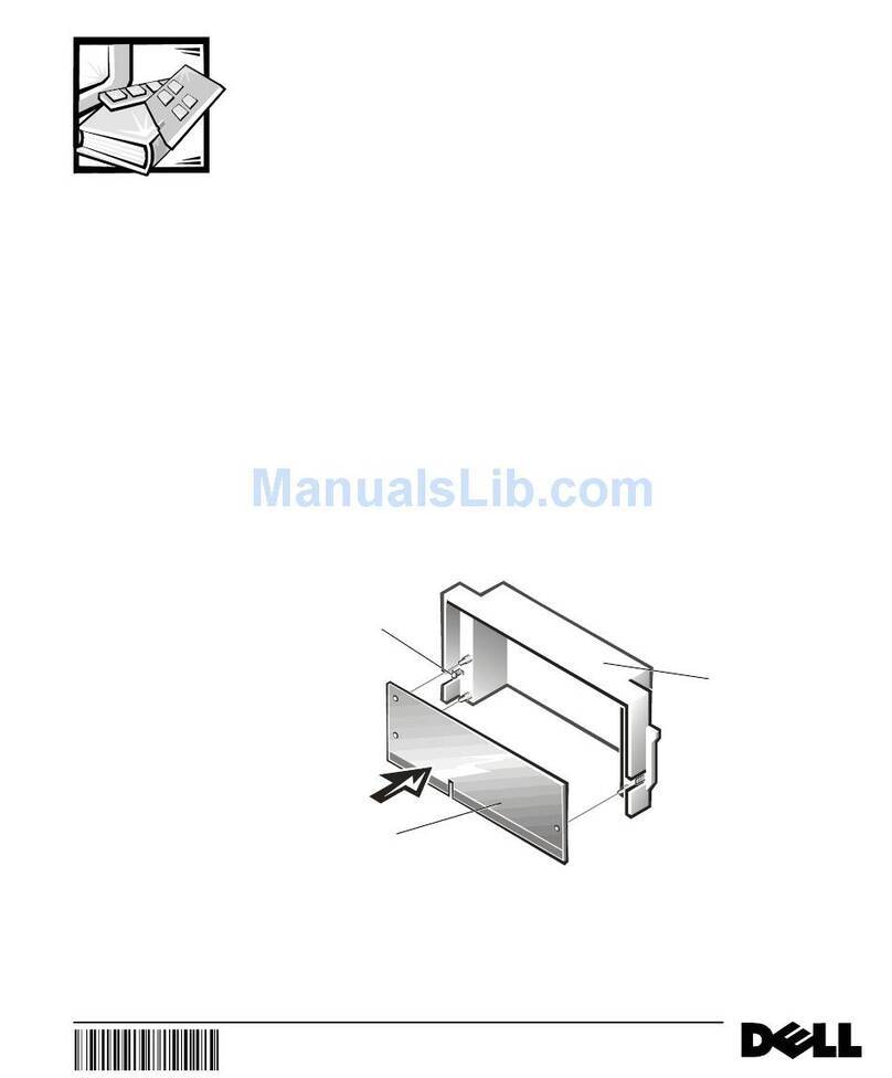
2. Insert the drive cage into the empty peripheral drive bay until the clips on the
drive rails snap into the sides of the peripheral drive bay (see Figure 1).
)LJXUH,QVWDOOLQJWKH'ULYH&DJH
,QVWDOOLQJWKH,&([WHQVLRQ&DEOH
To i n s t a l l t h e I 2C extension cable, perform the following steps:
1. Disconnect the I2C cable from the 20-pin connector on the system board and set
it to one side (see Figure 2).
drive rail
clip
drive cage
4 Dell PowerEdge 6300 and 4300 Systems 1 x 2 Backplane Installation Information
2. In the customer kit, locate the I 2C extension cable. (This cable has three
connectors: a 20-pin connector on one end and in the middle and a 10-pin
connector on the other end.)
3. Attach the 10-pin connector on the I 2C extension cable to the 10-pin connector on
the 1 x 2 backplane.
4. Attach the 20-pin connector on the I 2C extension cable to the 20-pin connector
on the system board.
5. Attach the loose end of the I 2C cable, which was set aside, to the middle connec-
tor of the I2C extension cable.
6. Attach a four-wire power cable to the power connector on the 1 x 2 backplane.
NOTE: The four-wire power cable is the standard cable found on all systems and
provides power to peripherals; for example, for a CD-ROM drive or tape drive.
)LJXUH,QVWDOOLQJWKH, &([WHQVLRQ&DEOH
10-pin connector on
1 x 2 backplane
I2C extension cable
hard-disk drive
SCSI backplane
I2C cable
20-pin connector
on system board
power connector
Dell PowerEdge 6300 and 4300 Systems 1 x 2 Backplane Installation Information5
,QVWDOOLQJWKH6&6,&DEOH
NOTE: The SCSI cable installation described in this document is a typical installation
of the SCSI cable used with the 1 x 2 backplane. You can install the SCSI cable
differently, depending on redundant arrays of independent disks (RAID) configurations
and the existence of SCSI peripheral cards. Refer to your operating system documen-
tation for information on how to set up your SCSI devices.
To install the SCSI cable to the 1 x 2 backplane, perform the following steps:
1. In the customer kit, locate the nonterminated 68-pin SCSI cable. (This cable has
two connectors at one end and one connector on the other end. See Figure 3.)
)LJXUH,QVWDOOLQJWKH6&6,&DEOHWR[%DFNSODQH
top drive connector
bottom drive
connector
SCSI cable
SCSI controller
on system board
6 Dell PowerEdge 6300 and 4300 Systems 1 x 2 Backplane Installation Information
2. On the end with two connectors:
a. Attach the connector at the end of the cable to the bottom drive connector
on the 1 x 2 backplane.
b. Attach the second connector to the top drive connector on the 1 x 2
backplane.
3. Attach the end with one connector to a SCSI controller on the system board.
&RQYHUWLQJWKH'ULYH&DUULHUV
You can use only 1-inch hard-disk drives with the 1 x 2 backplane. If you have 1.6-inch
hard-disk drive carriers that you want to use with your 1 x 2 backplane, you need to
place 1-inch hard-disk drives in the carrier and modify the 1.6-inch carriers to be 1 inch
in width. To modify the 1.6-inch carriers to 1-inch width, remove the spacer insert.
NOTE: To remove the spacer insert, use a screwdriver to pry open the clips on the
inside of the carrier release handle, and pull the spacer insert away from the carrier.
After you have installed your 1 x 2 backplane, see Installing and Removing SCSI
Hard-Disk Drives in Chapter 10 of the Installation and Troubleshooting Guide for
information on how to install your hard-disk drives.
NOTE: The 1 x 2 backplane sets the top drive to SCSI ID0 and the bottom drive to
SCSI ID1.

Other manuals for PowerEdge systems 6300

5

This manual suits for next models

1

Other Dell Server manuals

Dell PowerEdge 6600 User manual

Dell

Dell PowerEdge 6600 User manual

Dell PowerVault 530F User manual

Dell

Dell PowerVault 530F User manual

Dell PowerEdge 6450 Technical manual

Dell

Dell PowerEdge 6450 Technical manual

Dell PowerEdge 1850 Manual

Dell

Dell PowerEdge 1850 Manual

Dell PowerEdge M420 Operating manual

Dell

Dell PowerEdge M420 Operating manual

Dell EMC VxFlex Series User manual

Dell

Dell EMC VxFlex Series User manual

Dell PowerEdge 1655MC Manual

Dell

Dell PowerEdge 1655MC Manual

Dell D90D7 User manual

Dell

Dell D90D7 User manual

Dell PowerEdge R520 User manual

Dell

Dell PowerEdge R520 User manual

Dell Active Fabric Manager User manual

Dell

Dell Active Fabric Manager User manual

Dell EMC VxFlex Ready Node 13G User manual

Dell

Dell EMC VxFlex Ready Node 13G User manual

Dell DL4300 User manual

Dell

Dell DL4300 User manual

Dell PowerEdge 4600 User manual

Dell

Dell PowerEdge 4600 User manual

Dell PowerEdge C8000 User manual

Dell

Dell PowerEdge C8000 User manual

Dell PowerEdge C6220 User manual

Dell

Dell PowerEdge C6220 User manual

Dell PowerEdge R330 User manual

Dell

Dell PowerEdge R330 User manual

Dell PowerEdge PDU Managed LED User manual

Dell

Dell PowerEdge PDU Managed LED User manual

Dell PowerEdge M420 Quick start guide

Dell

Dell PowerEdge M420 Quick start guide

Dell PowerEdge C8220 User manual

Dell

Dell PowerEdge C8220 User manual

Dell POWEREDGE R710 User manual

Dell

Dell POWEREDGE R710 User manual

Dell PowerEdge R620 User manual

Dell

Dell PowerEdge R620 User manual

Dell POWEREDGE T300 User manual

Dell

Dell POWEREDGE T300 User manual

Dell PowerEdge R220 Quick start guide

Dell

Dell PowerEdge R220 Quick start guide

Dell PowerEdge M620 User manual

Dell

Dell PowerEdge M620 User manual

Popular Server manuals by other brands

IBM BladeCenter HS22 Product guide

IBM

IBM BladeCenter HS22 Product guide

HPE ProLiant MicroServer Gen10 Maintenance and service guide

HPE

HPE ProLiant MicroServer Gen10 Maintenance and service guide

Hitachi Advanced Server DS220 Hardware guide

Hitachi

Hitachi Advanced Server DS220 Hardware guide

Alcatel-Lucent OmniPCX Office RCE Small installation manual

Alcatel-Lucent

Alcatel-Lucent OmniPCX Office RCE Small installation manual

EtroVISION EV3151 installation guide

EtroVISION

EtroVISION EV3151 installation guide

HP ProLiant ML310e Gen Product End-of-Life Disassembly Instructions

HP

HP ProLiant ML310e Gen Product End-of-Life Disassembly Instructions

Supero SUPERSERVER 5016T-MTFB user manual

Supero

Supero SUPERSERVER 5016T-MTFB user manual

Intergraph InterServe 80 SL System reference

Intergraph

Intergraph InterServe 80 SL System reference

HP D7171A - NetServer - LPr Reference

HP

HP D7171A - NetServer - LPr Reference

Sun Oracle T5120 installation guide

Sun Oracle

Sun Oracle T5120 installation guide

NEC A1160 Technical overview

NEC

NEC A1160 Technical overview

Basalte CORE PLUS installation manual

Basalte

Basalte CORE PLUS installation manual

Sun Microsystems Sun Fire X2200 M2 Safety and compliance guide

Sun Microsystems

Sun Microsystems Sun Fire X2200 M2 Safety and compliance guide

Supermicro AS-1020A-8 user manual

Supermicro

Supermicro AS-1020A-8 user manual

Lenovo ThinkServer RD330 Informace o záruce a podpoře

Lenovo

Lenovo ThinkServer RD330 Informace o záruce a podpoře

Perle IOLAN SDS4 HL quick start guide

Perle

Perle IOLAN SDS4 HL quick start guide

Fujitsu PRIMERGY RX900 S2 operating manual

Fujitsu

Fujitsu PRIMERGY RX900 S2 operating manual

AutoPatch AVB-APWEB Specifications

AutoPatch

AutoPatch AVB-APWEB Specifications

manuals.online logo
manuals.online logoBrands
  • About & Mission
  • Contact us
  • Privacy Policy
  • Terms and Conditions

Copyright 2025 Manuals.Online. All Rights Reserved.