ABB aquamaster User manual

Installation Manual
IM/AM Issue 13
Electronic Commercial Water Meter
AquaMaster™

ABB
EN ISO 9001:2000
Cert. No. Q 05907
EN 29001 (ISO 9001)
Lenno, Italy – Cert. No. 9/90A
Stonehouse, U.K.
0255
Electrical Safety
This equipment complies with the requirements of CEI/IEC 61010-1:2001-2 'Safety Requirements for Electrical Equipment
for Measurement, Control and Laboratory Use'. If the equipment is used in a manner NOT specified by the Company, the
protection provided by the equipment may be impaired.
Symbols
One or more of the following symbols may appear on the equipment labelling:
Warning – Refer to the manual for instructions Direct current supply only
Caution – Risk of electric shock Alternating current supply only
Protective earth (ground) terminal Both direct and alternating current supply
Earth (ground) terminal The equipment is protected
through double insulation
The Company
We are an established world force in the design and manufacture of instrumentation for
industrial process control, flow measurement, gas and liquid analysis and environmental
applications.
As a part of ABB, a world leader in process automation technology, we offer customers
application expertise, service and support worldwide.
We are committed to teamwork, high quality manufacturing, advanced technology and
unrivalled service and support.
The quality, accuracy and performance of the Company’s products result from over 100 years
experience, combined with a continuous program of innovative design and development to
incorporate the latest technology.
The UKAS Calibration Laboratory No. 0255 is just one of the ten flow calibration plants
operated by the Company and is indicative of our dedication to quality and accuracy.
Information in this manual is intended only to assist our customers in the efficient operation of our equipment. Use of this
manual for any other purpose is specifically prohibited and its contents are not to be reproduced in full or part without prior
approval of the Technical Publications Department.
Health and Safety
To ensure that our products are safe and without risk to health, the following points must be noted:
1. The relevant sections of these instructions must be read carefully before proceeding.
2. Warning labels on containers and packages must be observed.
3. Installation, operation, maintenance and servicing must only be carried out by suitably trained personnel and in accordance with
the information given.
4. Normal safety precautions must be taken to avoid the possibility of an accident occurring when operating in conditions of high
pressure and/or temperature.
5. Chemicals must be stored away from heat, protected from temperature extremes and powders kept dry. Normal safe handling
procedures must be used.
6. When disposing of chemicals ensure that no two chemicals are mixed.
Safety advice concerning the use of the equipment described in this manual or any relevant hazard data sheets (where applicable) may be
obtained from the Company address on the back cover, together with servicing and spares information.

Electronic Commercial Water Meter
AquaMaster™ Contents
IM/AM Issue 13 1
Contents
1 Introduction ...................................................................................................................................... 2
2 Mechanical Installation .................................................................................................................... 3
2.1 Unpacking ............................................................................................................................... 3
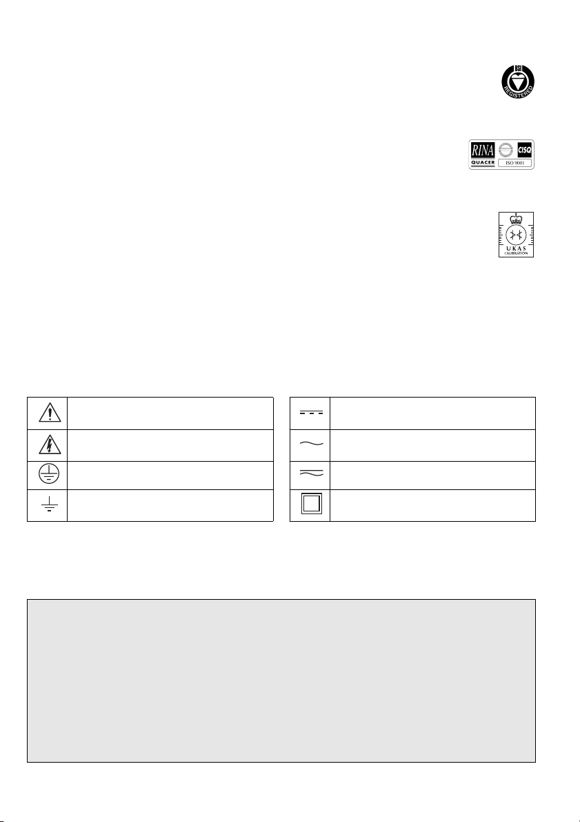
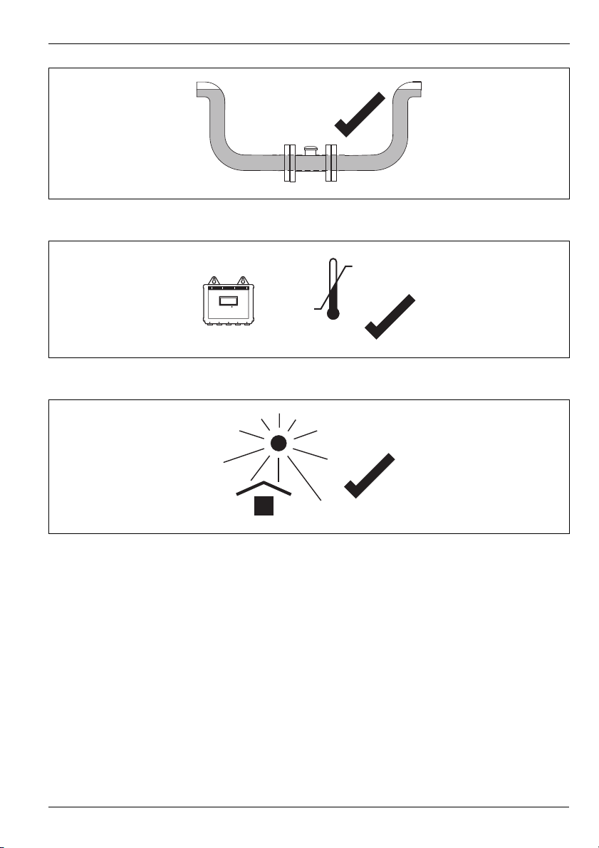
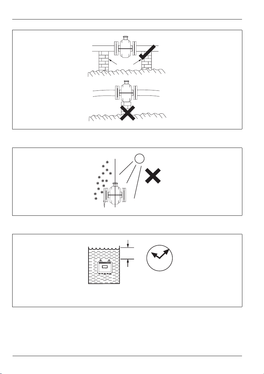
2.2 Installation Conditions .............................................................................................................. 3
2.3 Transmitter Dimensions ........................................................................................................... 9
2.4 GSM-equipped Transmitters .................................................................................................. 10
2.4.1 GSM Antenna Installation ............................................................................................ 10
2.4.2 Connecting a Remote Antenna .................................................................................... 11
2.4.3 Installing a SIM Card .................................................................................................... 12
3 Electrical Installation ..................................................................................................................... 13
3.1 Bonding/Grounding ............................................................................................................... 13
3.2 Connections .......................................................................................................................... 19
3.2.1 Sensor Terminal Box Connections (Remote Versions only) .......................................... 19
3.2.2 Environmental Protection ............................................................................................. 20
3.2.3 Transmitter Connections ............................................................................................. 21
3.3 Input/Output Connections ..................................................................................................... 24
3.3.1 Frequency Outputs ...................................................................................................... 24
3.3.2 Alarm Interface ............................................................................................................ 25
3.3.3 Connector Input/Output Connections .......................................................................... 26
3.3.4 MIL Connector Input/Output (Option) AquaMag™ x10 Pulse Output Compatibility ...... 27
3.3.5 ScanReader Interface (Option) ..................................................................................... 27
3.3.6 Local Computer Connection ........................................................................................ 28
3.3.7 Remote Computer Connection .................................................................................... 29
3.3.8 Power Supply Connection ........................................................................................... 30
3.3.9 Pressure Transducer (Optional) .................................................................................... 31
3.3.10 Environmental Protection ........................................................................................... 32
4 Start-Up And Operation ................................................................................................................. 33
4.1 Connecting Batteries ............................................................................................................. 33
4.2 Start-up ................................................................................................................................. 33
4.3 Display Activation .................................................................................................................. 35
4.4 Replacing a Battery ............................................................................................................... 36
4.4.1 Spares Kits .................................................................................................................. 36
4.4.2 Battery Changing Procedures ...................................................................................... 37
5 Specification .................................................................................................................................. 39
Appendix A GSM-Equipped Units – Safety Precautions ................................................................... 50
Appendix B AquaMaster Block Diagram ........................................................................................... 51
Notes .................................................................................................................................................. 52

Electronic Commercial Water Meter
AquaMaster™ 1 Introduction
2IM/AM Issue 13
1 Introduction
AquaMasterTM is a range of high performance electromagnetic flowmeters for the measurement of
electrically conductive fluids and are normally supplied as factory configured, calibrated systems.
Warning.
Installation and maintenance must be carried out only by suitably trained personnel.
Read all relevant sections of this manual before selecting a location.
The safety requirements of this equipment, any associated equipment and the local environment
must be taken into consideration during installation.
Install and use this equipment in accordance with relevant national and local standards.
Specific safety precautions apply to the use of the GSM engine which forms part of the
GSM-equipped version of this product. If the unit purchased has GSM-capability, read Appendix
A on page 50 before selecting a location.

Electronic Commercial Water Meter
AquaMaster™ 2 Mechanical Installation
IM/AM Issue 13 3
2 Mechanical Installation
2.1 Unpacking
2.2 Installation Conditions
Fig. 2.1 Unpacking
Caution. Do NOT exceed the maximum working pressure marked on the equipment.
Fig. 2.2 Spillage
Fig. 2.3 Vibration
AquaMaster
AquaMaster
AquaMaster AquaMaster

Electronic Commercial Water Meter
AquaMaster™ 2 Mechanical Installation
4IM/AM Issue 13
Fig. 2.4 Localized Heat
Fig. 2.5 Siting
Fig. 2.6 Straight Pipe Requirements
Allow room to
read display
>2 x pipe dia.
minimum
>5 x pipe dia.
minimum
Flow Direction

Electronic Commercial Water Meter
AquaMaster™ 2 Mechanical Installation
IM/AM Issue 13 5
Fig. 2.7 Fluid Level
Fig. 2.8 Within Temperature Limits
Fig. 2.9 Shade
60°C 140°F)
Maximum
20°C 4°F)
Minimum

Electronic Commercial Water Meter
AquaMaster™ 2 Mechanical Installation
6IM/AM Issue 13
Fig. 2.10 Above Ground
Fig. 2.11 Temperature Difference
Fig. 2.12 Within Environmental Rating
Supports
< 2m
78in)
IP68 (NEMA6P/
ENCLOSURE6P)
Submerged
9 Months
Accrued Time

Electronic Commercial Water Meter
AquaMaster™ 2 Mechanical Installation
IM/AM Issue 13 7
Fig. 2.13 Underground
Fig. 2.14 Cable Routing
Fig. 2.15 Gasket Fitting
Backfill Recommended)
Adequate
Protection
Plate
80°C 176°F)
Maximum
10°C 14°F)
Minimum
Fit gaskets
Gasket same
size as pipe

Electronic Commercial Water Meter
AquaMaster™ 2 Mechanical Installation
8IM/AM Issue 13
Fig. 2.16 Separation of Sensors
Fig. 2.17 Access to Transmitter
0.7m 2.3 ft)
minimum
For access to batteries, display
and communication connector.

Electronic Commercial Water Meter
AquaMaster™ 2 Mechanical Installation
IM/AM Issue 13 9
2.3 Transmitter Dimensions
Fig. 2.18 Transmitter Dimensions
Fig. 2.19 GSM Antenna Installation
Transmitter Mounting Plate
176 7)
140
5.5)
Installation and wiring acces
s
300 11.8) minimum 450 17.7)
preferred
Allowance for cable bend - each side
130 5.1) standard)
230 9) armored)
155mm
6.1)
146 5.75)
125 4.9)
170
6.7)
ø6.5 1/4)
ø13 1/2)
ø6.5 1/4)
150
5.9)
AquaMaster
Dimensions in mm in.)
50mm50mm
Remote
Antenna
Integral
Antenna

Electronic Commercial Water Meter
AquaMaster™ 2 Mechanical Installation
10 IM/AM Issue 13
2.4 GSM-equipped Transmitters
2.4.1 GSM Antenna Installation
Before deciding on an antenna mounting location, check that the local signal strength for the chosen
mobile phone network is satisfactory. Use the GSM-equipped transmitter's integral signal strength test
facility to establish signal strength. Refer to 'Commissioning test for signal strength' in the Quick Reference
Guide for the AquaMaster S with GSM (IM/AMG–QRG).
If a GSM-equipped transmitter is not available, a standard mobile phone on the same network, positioned
as close as possible to the intended location, will give a good indication of local signal strength. For GSM
and logger download services, a minimum of two visible signal strength indicator 'bars' are recommended.
For SMS text, a minimum of one visible signal strength indicator 'bar' is recommended.
The following must also be observed when deciding on the antenna mounting location:
For best results, mount the antenna as high above local ground level as possible.
If the antenna must be mounted below ground, achieve optimum results by ensuring:
– there is a strong mobile phone network signal at ground level
– the antenna is mounted 50mm below the chamber cover, which must be plastic – see
Fig. 2.19
Ensure the antenna will not become submerged under water – see Fig. 2.19.
Metallic enclosures will seriously degrade the signal. If an enclosure is used it must be non-metallic.
Do not mount the antenna closer than 50mm to any solid wall or surface – see Fig. 2.20.
Do not mount the antenna beneath a solid surface (e.g. metal cover, floor/ceiling, etc).
Fig. 2.20 GSM Antenna Installation
³ 50mm
2 in.)

Electronic Commercial Water Meter
AquaMaster™ 2 Mechanical Installation
IM/AM Issue 13 11
2.4.2 Connecting a Remote Antenna
Fig. 2.21 Connecting a Remote Antenna
SIM card
holder
Attach the antenna
cable plug securely
to the antenna
connector.
1If the transmitter is not fixed in any way, arrange or
hold it with the top cover uppermost.
2Wash off any loose dirt from the case using plain
water.
Remove the transmitter top cover and battery
mounting tray see Fig. 3.12.
3
Pass the antenna cable through
a spare cable gland.
4
5
6Tighten the cable gland.
Refit the battery mounting tray and the transmitter
top cover see Fig. 3.12.
7

Electronic Commercial Water Meter
AquaMaster™ 2 Mechanical Installation
12 IM/AM Issue 13
2.4.3 Installing a SIM Card
Fig. 2.22 Installing a SIM Card
Warning. Disconnect all power from the transmitter before opening the SIM card holder. If the power is
not disconnected the SIM card may be corrupted and therefore be unusable.
1If the transmitter is not fixed in any way, arrange or
hold it with the top cover uppermost.
2Wash off any loose dirt from the case using plain
water.
Remove the transmitter top cover and battery
mounting tray see Fig. 3.12.
3
4
6Close the SIM card holder cover and slide into
locked position.
Refit the battery mounting tray and the transmitter
top cover see Fig. 3.12.
7
Slide to unlock and open the
SIM card holder cover
5Insert the SIM card,
contact side down
and bevelled edge
first, into the SIM card
holder.

Electronic Commercial Water Meter
AquaMaster™ 3 Electrical Installation
IM/AM Issue 13 13
3 Electrical Installation
3.1 Bonding/Grounding
Caution. For safety reasons and optimum performance, the flowmeter, pipelines and medium must be
correctly bonded and grounded according to regulations.
Note.
The flow sensor must not be connected to a ground spike.
For bonding connections use ≥4mm2 (<10AWG) cable.
Sensors ≤80mm do not require grounding rings.
Connect the transmitter ground connection to the flowmeter body ground – see Fig. 3.6 and
Fig. 3.7.
Fig. 3.1 All Metal Pipe, Including Lined Metal Pipe.
Fluid Contact Rings
See Figs. 3.6 and 3.7
Key for igs. 3.1 to 3.9
Metal Pipes
Plastic Pipes

Electronic Commercial Water Meter
AquaMaster™ 3 Electrical Installation
14 IM/AM Issue 13
Fig. 3.2 Metal Pipe With Flange Adaptor
Fig. 3.3 Flanged Metal Pipe to Plastic Pipe
Fluid Contact Rings
See Figs. 3.6 and 3.7
Insulation
Fluid Contact Rings
See Figs. 3.6 and 3.7

Electronic Commercial Water Meter
AquaMaster™ 3 Electrical Installation
IM/AM Issue 13 15
Fig. 3.4 Metal Pipe With Plastic Make-Up Insert
Fig. 3.5 All Plastic Pipe
Fluid Contact Rings
See Figs. 3.6 and 3.7
Fluid Contact Rings
See Figs. 3.6 and 3.7

Electronic Commercial Water Meter
AquaMaster™ 3 Electrical Installation
16 IM/AM Issue 13
Fig. 3.6 Battery Powered Transmitter Mounted in a Chamber
Fig. 3.7 Mains or Battery Powered Transmitter in Roadside Cabinet with Local Ground

Electronic Commercial Water Meter
AquaMaster™ 3 Electrical Installation
IM/AM Issue 13 17
Fig. 3.8 Pipelines With Cathodic Protection, DN≥100mm
Caution. Do NOT ground Cathodically Protected Systems.
Fluid Contact Rings
Insulating Sleeve
and Washer
not supplied)
Insulated connecting wire
not supplied). Must be
adequately rated to carry
cathodic currents.
Gasket Gasket
Bonding Cable
supplied)
Fluid Contact
Ring
Bonding Cables
supplied)

Electronic Commercial Water Meter
AquaMaster™ 3 Electrical Installation
18 IM/AM Issue 13
Fig. 3.9 Pipelines With Cathodic Protection, DN 40mm to 80mm
Caution. Do NOT ground Cathodically Protected Systems.
Insulating Sleeve
and Washer
not supplied)
Insulated connecting wire
not supplied). Must be
adequately rated to carry
cathodic currents.
Gasket
Bonding Cable
supplied)
Other manuals for aquamaster
3
Table of contents
Other ABB Measuring Instrument manuals

ABB
ABB GLA131 Series User manual

ABB
ABB MagMaster User manual

ABB
ABB AX400 Series User manual

ABB
ABB ODIN User manual

ABB
ABB GLA451 User manual

ABB
ABB Endura AZ20 series User manual

ABB
ABB FSM4000 Series User manual

ABB
ABB WaterMaster User manual

ABB
ABB ScreenMaster RVG200 User manual

ABB
ABB CoreSense M10 User manual

ABB
ABB Advance Optima Caldos 15-Ex User manual

ABB
ABB HART FEP300 Installation and operation manual

ABB
ABB B21 User manual

ABB
ABB AX410 User manual

ABB
ABB B21 User manual

ABB
ABB EXCOUNT-II User manual

ABB
ABB Endura AZ20 series User manual

ABB
ABB Nitrate 8236 User manual

ABB
ABB EQmatic User manual

ABB
ABB Navigator 550 User manual