Delsys Trigno Avanti User manual

Trigno®Wireless
Biofeedback System
__
Avanti Analog Input
Adapter
User’s Guide
Copyright © 2019 by Delsys Incorporated
MAN-021-2-0
MP1289A
August 2019
No part of this document may be reproduced, transmitted, transcribed, stored in a retrieval
system, or translated into any language in any form by any means without the written
permission of Delsys Inc.
Download EMGworks® at
www.delsys.com/emgworks

Important Information...............................................................................3
Intended Use...........................................................................................................3
Contraindications ....................................................................................................3
Technical Service and Support ................................................................................ 3
Warnings and Precautions ......................................................................................4
Device Information.................................................................................................. 5
Windows PC Requirements.....................................................................................6
Android Device Requirements................................................................................. 6
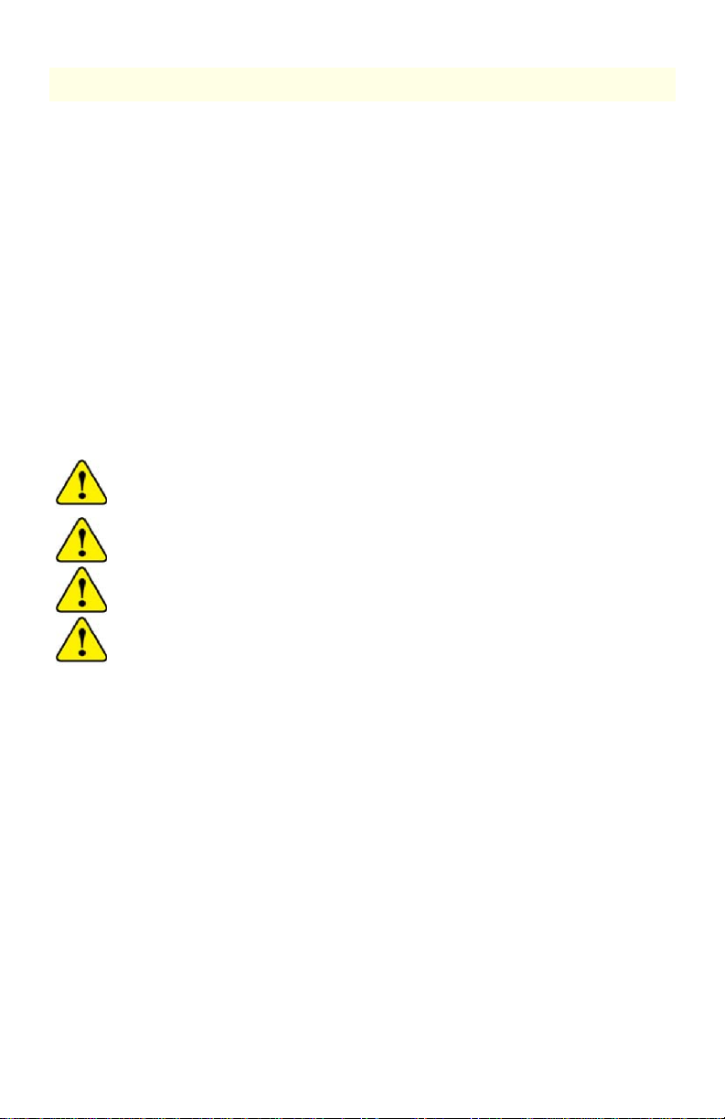
Trigno System Overview ............................................................................ 7
Trigno Analog Adapter Features.............................................................................. 7
Robust +/-5V Input Signal .................................................................................................. 8
Industry Standard Connectors ........................................................................................... 8
Pushbutton Event Marker.................................................................................................. 8
Dual Mode “BLE-Base” Communication ............................................................................ 8
Wireless Communication................................................................................................... 8
Data Synchronization......................................................................................................... 8
Rechargeable Battery......................................................................................................... 8
Sealed Enclosure................................................................................................................ 9
Internal Magnetic Switch ................................................................................................... 9
Sensor LED Feedback States .............................................................................................. 9
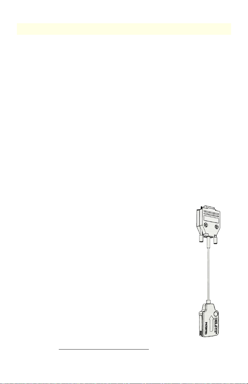
Getting Started with the Analog Input Adapter ....................................... 11
Configuring the Trigno Analog Input Adapter .......................................................11
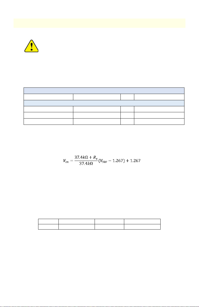
Using the Analog Outputs (if Equipped)................................................................11
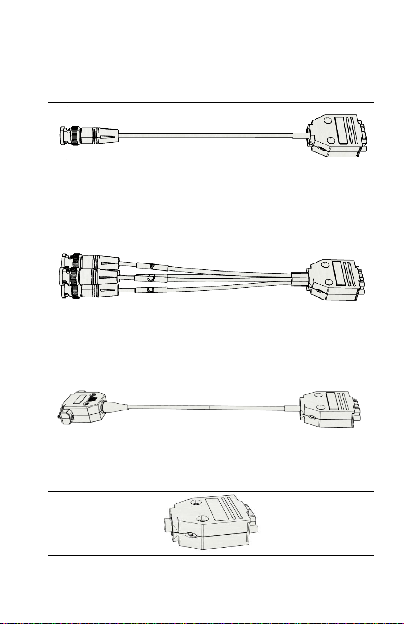
Analog Input Adapter Connections .......................................................................12
Single Channel BNC Connection (DC-X06)........................................................................ 13
Quad Channel BNC Connection (DC-X07)......................................................................... 13
Biodex Isokinetic Device Connection (DC-X05) ................................................................ 13
Event Marker Button (DC-X08) ........................................................................................ 13
Maintenance and Care............................................................................. 14
Trigno Sensors.......................................................................................................14
Specifications........................................................................................... 15
Physical Specifications...........................................................................................15
Electrical Specifications.........................................................................................15
Analog Input Measurement Data Modes..............................................................16

Trigno Avanti Analog Input Adapter User’s Guide 3
Important Information
Intended Use
The Trigno Analog Adapters are components of the Trigno®Wireless
Biofeedback System used view +/-5V output signals. This system is a battery-
powered biofeedback device that enables researchers and clinicians to acquire
EMG and related signals from subjects for biofeedback and research purposes.
The System is intended for relaxation training and muscle reeducation.
Interpretation of the EMG and supporting signals by a qualified individual is
required.
Rx ONLY
Contraindications
DO NOT USE on Patients with implanted electronic devices of any
kind, including cardiac pace-makers or similar assistive devices,
electronic infusion pumps, and implanted stimulators.
DO NOT USE on irritated skin or open wounds.
DO NOT USE on Patients with allergies to Silver.
DO NOT USE in critical care applications.
Technical Service and Support
For information and assistance please visit our web site at:
www.delsys.com
Contact us at:
Telephone: (508) 545 8200

4 MAN-021-2-0
Warnings and Precautions
Consult all accompanying documents for precautionary statements and
other important information.
Consult accompanying user’s guide for detailed instructions.
Keep the device dry. The ingress of liquids into the device may compromise
the safety features of the device.
Handle with care.
Sensitive electronic device. Avoid static discharges. Do not operate or store
near strong electrostatic, electromagnetic, magnetic or radioactive fields.
Interference from external sources may decrease the signal-to-noise ratio
or result in corrupted data.
Connect only to Delsys-approved devices.
Connecting a patient to high-frequency surgical equipment while using
Delsys EMG systems may result in burns at the site of the EMG sensor
contacts
Immediately discontinue device use if skin irritation or discomfort occurs.
Immediately discontinue device use if a change in the device’s
performance is noted. Contact Delsys technical support for assistance.
Delsys Inc. guarantees the safety, reliability, and performance of the
equipment only if assembly, modifications and repairs are carried out by
authorized technicians; the electrical installation complies with the
appropriate requirements; and the equipment is used in accordance with
the instructions for use.
Device contains a Lithium-Polymer battery. Do not damage, crush, burn,
freeze or otherwise mishandle the device. Recharge only with the
approved power supply and recharger.
Report any serious incidents with the device to Delsys at 508 545 8200 or
Trigno Systems should be stored and operated between 5 and 45 degrees
Celsius due to the presence of an internal Lithium Polymer rechargeable
cell. Storing or operating the device, and consequently the cell, outside of
this temperature range may compromise the integrity and the safety
features of the cell.

Trigno Avanti Analog Input Adapter User’s Guide 5
Device Information
Complies with Requirements put forth by the Medical Device Directive
93/42/EEC. Class I device, Annex VII. Type BF device (IEC 60601-1)
Isolated device, (Class II, IEC 60601-1)
Type BF Equipment.
Date of Manufacturing (appears on device)
Manufacturer:
Delsys Inc.
23 Strathmore Rd.
Natick, MA, 01760, USA
Serial Number (appears on device)
Dispose the device according to local rules for electronic waste.
Authorized Representative:
EMERGO EUROPE
Prinsessegracht 20, 2514 AP The Hague
The Netherlands
Trigno Wireless Biofeedback System
Sensor Model: SP-W06-025 (“Trigno Avanti Analog Input Adapter”)
System Model: DS-T03
FCCID: W4P-SP-W06 (Sensor)
FCCID: W4P-SP-W02 (Base Station)
IC: 8138A-DST03 (System)
211-190332 (DS-T03)
211-190333 (SP-W06)
This device complies with Part 15 of the FCC Rules and Industry Canada’s
RSS-210 License Exempt Standards. Operation is subject to the following
two conditions: (1) This device may not cause harmful interference. and (2)
this device must accept any interference received, including interference
that may cause undesired operation.
This Class B digital apparatus complies with Canadian ICES-003.
Cet appareil est conforme à des règlements d'Industrie Canada exempts
de licence standard RSS (s). Son fonctionnement est soumis aux deux
conditions suivantes: (1) Ce dispositif ne doit pas causer d'interférences
nuisibles, et (2) cet appareil doit accepter toute interférence reçue, y
compris les interférences pouvant entraîner un fonctionnement
indésirable.

6 MAN-021-2-0
Cet appareil numériqué de la classe B est conformé à la norme NMB-003
du Canada
This product complies with FCC OET Bulletin 65 radiation exposure limits
set forth for an uncontrolled environment.
To reduce potential radio interference to other users, the antenna type
and its gain should be so chosen that the equivalent isotropically radiated
power (EIRP) is not more than that required for successful communication.
This equipment has been tested and found to comply with the limits for a
Class B digital device, pursuant to Part 15 of the FCC Rules. These limits are
designed to provide reasonable protection against harmful interference in
a residential installation. This equipment generates, uses, and can radiate
radio frequency energy and, if not installed and used in accordance with
the instructions, may cause harmful interference to radio communications.
There is no guarantee that interference will not occur in a particular
installation. If this equipment does cause harmful interference to radio or
television reception, which can be determined by turning the equipment
off and on, the user is encouraged to try to correct the interference by one
or more of the following measures: Reorient or relocate the receiving
antenna; increase the separation between the equipment and receiver;
Connect the equipment into outlet on a separate circuit.
Pursuant to FCC 15.21 of the FCC rules, changes not expressly approved by
Delsys Inc. could void the User’s authority to operate the equipment.
Please refer to the main Trigno System User Guide for additional
information.
Windows PC Requirements
•EMGworks 4.7 or later
•Windows 7, 8.1, 10
•One USB 2.0 port
•At least 2.0 GHz processor clock speed
•At least 2 GB system memory
•1280x1024 (SXGA) display resolution or better
•50 GB hard disk storage (minimum)
Android Device Requirements
•Android V 7 (Nougat) operating system or later
•BLE 4.2 support
•RAM 1GB minimum
•Storage 8 GB minimum
•Screen Resolution 2048x1536 (recommended)
•Recommended Tablet:
Samsung Galaxy Tab S2
8”screen, 32 GB, WI-FI
(SM-T713NZKEXAR)
or
Samsung Galaxy Tab S5e
10.5" AMOLED screen, 64 GB Storage
Android 9.0 (Pie), WiFi & Bluetooth v.5.0

Trigno Avanti Analog Input Adapter User’s Guide 7
Trigno System Overview
The Trigno®Analog Input Adapter is a component of the Trigno Wireless
Biofeedback System, a device designed to make EMG (electromyographic) and
biofeedback signal detection reliable and easy. The system transmits signals
from the Trigno sensors to a receiving base station using a time-synchronized
wireless protocol which minimizes data latency across sensors. The core
architecture of the Trigno System is designed to support high fidelity EMG
signals, along with complementary biofeedback signals such as movement data,
force signals, contact pressure events and timing and triggering information.
For mobile biofeedback applications, Trigno Sensors can communicate with
Bluetooth BLE 4.2 compliant host devices. The system is also capable of
integrating with 3rd party lab equipment through a variety of interfaces which
include analog signal generation, triggering scenarios and digital integration
through the Trigno SDK (Software Development Kit) and the Trigno API
(Application Program Interface). Refer to the Trigno System User Guide for
System information and operational details.
Trigno Analog Adapter Features
The Trigno Analog Adapters are capable of sampling up to 4 channels of +/-5V
analog signals from 3rd party devices. The adapter is terminated in a 9-Pin DSUB
female connector and can be fitted with up to 4 BNC connectors.
•Configurable bandwidth DC-100 Hz or DC-1000 Hz
•Max input range of +/-5V
•Up to 4 independent channels
•16 bits of resolution
•software selectable operational modes
•inter-sensor latency < 1 sample period
•wireless transmission range 20+m1
•self-contained rechargeable battery
•battery charge monitoring and status indicator
•environmentally sealed enclosure
•low power mode
•auto shutoff
•internal magnetic switch
•LED User Feedback
•Industry Standard DSUB-9 connector
•Optional Industry Standard BNC connectors
•Optional push-button attachment for event triggering
1
. Communication distance is dependent on the RF operating environment.

8 MAN-021-2-0
Robust +/-5V Input Signal
The analog input adapter can accept 4 voltage signals in the +/-5V range and
sample these to a resolution of 16 bits alongside other data from Trigno
sensors. The adapter has a selectable filter of DC-100 Hz or DC-1000 Hz,
depending on the configured mode that the adapter is operated in (see mode
selection tables in the appendices).
Industry Standard Connectors
To facilitate connections to signals from 3rd party devices, the analog input
adapter terminates in a 9-pin female DSUB connector. Mating components are
available to support BNC connections or direct connections to isokinetic
devices.
Pushbutton Event Marker
An optional pushbutton attachment to analog input adapter is available and can
be used to manually denote events during biofeedback sessions. Events are
marked as high-to-low signal transitions and are time synchronized with all
other signal data from the Trigno System.
Dual Mode “BLE-Base” Communication
Trigno sensors are capable of communication with a PC-connected Base station
using the Trigno custom wireless communication protocol, or with Android
devices using the Bluetooth Low Energy (BLE) industry standard protocol. Note
that the information bandwidth when operating over Bluetooth is limited by
the Bluetooth protocol and the host device capabilities.
Wireless Communication
The Trigno wireless communication scheme offers robust data transmission for
up to 16 Trigno sensors operating in full bandwidth mode, with a nominal
distance of 20m. Under optimal environmental conditions (no RF path
obstructions or interfering sources), this nominal distance can be notably
superseded.
Data Synchronization
Data from each sensor and from each channel within a sensor are time
synchronized over the Trigno wireless communication protocol so no time skew
between data exists. A maximum of 16 sensors can stream data to a host base
station at one time. These features are available only when communicating with
the PC-connected Base Station; the Bluetooth/BLE protocol does not guarantee
latency.
Rechargeable Battery
Sensors contain a sealed rechargeable lithium polymer battery for continuous
use which can be extended when making use of low power modes. Actual
duration will depend on usage conditions, which are expected to vary between
4 to 8 hours of performance. Charge status is conveniently reported through
the wireless communication protocol.

Trigno Avanti Analog Input Adapter User’s Guide 9
Sealed Enclosure
The environmentally sealed enclosure protects the electronics from the ingress
of liquids and other environmental elements and provides a high standard of
user safety and durability.
Internal Magnetic Switch
The Trigno sensors are equipped with an internal magnetic switch which is used
to turn the sensors “on” and to perform RF pairing operations. To activate the
internal magnetic switch, the sensor must be placed on the magnet lock label
located on the Base Station charging cradle. The internal magnetic switch will
only react when the sensors are undocked from the charger or when the
software is performing an RF pairing operation. Exposure to any magnetic fields
outside of these 2 qualifying conditions will be ignored by the sensor. The
internal magnetic switch is a feature which removes the need for a mechanical
button and improves sensor durability and performance. Common household
magnets can be used to perform these functions as well.
Sensor LED Feedback States
Trigno Avanti sensors indicate their status through various LED Arrow colors
and blink patterns as indicated in the table below. Each of these states is
described in subsequent sections of this User Guide.
State
Color
Pattern
Arrow Display
Common States
1
Power Off
Off
none
2
Power On/Activate
White/Green
fade
/
3
Charging
Amber
solid
4
Charge Complete
Green
solid
5
Identification Mode
White
rapid flash
/ /
6
Scan (Startup)
Amber/Cyan
slow flash
/
7
Power Up Error
Red
slow flash
/
Trigno RF Mode
8
Scan (Base)
Amber/Green
Slow flash
/
9
Low Power Scan (Base)
Amber
Occasional Flash
/
10
Data Collection (Base)
Green
slow flash
/
11
Configuration Change (Base)
Green
rapid flash (3x)
/ /
12
Pairing (Base)
Amber
solid
13
Pairing Success (Base)
Green
rapid flash (≥6x)
/ /
/ /
14
Pairing Fail (Base)
Red
double flash(≥3x)
/ /
BLE Mode
15
Advertise (BLE)
Cyan
Slow flash
/
16
Low Power Advertise (BLE)
Cyan
occasional flash
/
17
Data Collection (BLE)
Blue
slow flash
18
Idle (BLE)
Magenta
slow flash
Table 1: Sensor LED functions.

10 MAN-021-2-0
LED State Descriptions
1) Power Off: No LED arrow activity is present when the sensor is off.
2) Power On: When undocked, the sensor illuminates white and fades to
black. A magnetic field will turn the sensor on within 6 seconds, otherwise
the arrow fades to dark and sensor turns off.
3) Charging: Sensor Charging in the Trigno Base Station is denoted by
continuous amber LED arrow illumination
4) Charge Complete: Once the internal sensor battery has been fully
recharged, the LED arrow illuminates to continuous green.
5) Identification Mode: The arrows blink white upon this software command
so that it can be easily identified and located.
6) Startup Scan: upon power-up the sensor actively searches for a host to
connect to (PC Base Station or BLE tablet).
7) Power Up Error: Sensor fails self-check on power up
8) Scan (Base): Sensor was previously paired and is scanning for the active
base station.
9) Low Power Scan (Base): Sensor was previously paired and has been
scanning for the active base station for more than 5 minutes.
10) Data Collection (Base): Data from sensor are streaming to a paired PC-
connected base station.
11) Configuration Change (Base): Sensor acknowledges change in
configuration sensor from host base station.
12) Pairing (Base): Sensor is performing a pair operation with the base host.
13) Pairing Success (Base): Sensor successfully completes a pair operation with
the Base Station host.
14) Pairing Fail (Base): The pair operation did not complete successfully with
the Base Station host.
15) Advertise (BLE): Sensor is broadcasting to connect with a BLE host.
16) Low Power Advertise (BLE): Sensor is broadcasting to connect with a BLE
host for more than 5 minutes.
17) Data Collection (BLE): Sensor is sampling and streaming data to BLE host.
18) Idle (BLE): Sensor is waiting for a Bluetooth BLE command.

Trigno Avanti Analog Input Adapter User’s Guide 11
Getting Started with the Analog Input Adapter
Please refer to the Trigno System User guide for key
operational details regarding the base station, sensor charging,
and initiating the sensor.
Configuring the Trigno Analog Input Adapter
Once paired to the system, the analog input adapter can be configured in the
following ways:
Input Sensing Characteristics
Input Range1
+/-5 Volts
Frequency Considerations
Bandwidth1
DC-100 Hz
or
DC-1000 Hz
Filter
Butterworth, 2 pole
or
Bessel, 2 pole
Sampling Considerations3
Single data slot modes
Multi-data slot modes
1Take care to ensure that voltage inputs do not exceed +/-5V in amplitude.
2Accuracy of voltage signal representation is dependent on the series output impedance
of the device to which the adapter is connected. A series output impedance of 50 ohms
or less is recommended. Signal amplitude and offset is derated by the following equation
as a function of source output impedance:
3Refer to mode tables in the appendix for additional details on sampling options.
Using the Analog Outputs (if Equipped)
The Trigno System provides simultaneous analog signal reconstruction of data
being detected by all active sensors. These signals are made available on the
68-pin connectors located on the Base Station and range cover the +/-5V range.
Analog outputs are engaged through software and are only available for specific
sensor sampling configurations as stated below:
Sampling Rate
Data Type
Bandwidth
Ch. x.1
1926 sa/sec
EMG
20-450 Hz
Table 2: Analog Output signal details. Note that sampling rates are approximate; please
refer to specification table for precise sampling periods.

12 MAN-021-2-0
Figure 1: Analog Output Data Flowchart
Refer to the Trigno System User Guide for more information on Analog Output
Operation.
Analog Input Adapter Connections
Users can interface with the analog adapter according to the signal map below,
using commonly found catalog 9-Pin D-SUB male mating connectors with
female thumb-screw sockets. The recommended mating connector with jack
screws is Norcomp 172-009-102R031 along with matching plastic hood,
Norcomp 970-009-010R011. Standard 9-pin DSUB alternative connectors are
acceptable.
Adapter Channel
DSUB Pin
A
6
B
9
C
7
D
8
Common
1,2,3,4,5
Figure 2: Trigno Avanti Analog Input Adapter. DSUB connector makes ground and 4
channel inputs available for sampling +/-5V signals. Bandwidth setting of DC-100 Hz is
recommended for single BW data slot operation and DC-1000 Hz will require multi-slot
acquisition.

Trigno Avanti Analog Input Adapter User’s Guide 13
Single Channel BNC Connection (DC-X06)
The single channel BNC connector makes available channels “A” from the
adapter to an industry standard female BNC connector. The remaining 3
channels are inaccessible when using this attachment. Single data slot modes
can support both bandwidth options of DC-100 Hz and DC-1000 Hz.
Figure 3: The Single Channel BNC attachment.
Quad Channel BNC Connection (DC-X07)
The quad channel BNC attachment maps channels “A” through “D” to industry
standard female BNC connectors. Single data slot modes can support the low
bandwidth options of DC-100 Hz, while multi-data slot modes support the high
bandwidth option of DC-1000 Hz.
Figure 4: The Quad Channel BNC attachment.
Biodex Isokinetic Device Connection (DC-X05)
A conversion cable for Biodex Isokinetic devices is available that maps the 9-pin
DSUB connection of Analog Input Adapter to the 15-pin DSUB connector of the
Analog Output port of Biodex Isokinetic devices.
Figure 5: The analog signal connector for Biodex Isokinetic devices.
Event Marker Button (DC-X08)
A push-button attachment is available that can be used to manually toggle a
signal line from a voltage “high” to a voltage “low” signal to mark events.
Figure 6: Event Marker Button attachment.

14 MAN-021-2-0
Maintenance and Care
Trigno Sensors
Trigno sensor are encased in a sealed polycarbonate enclosure. The following
points should be kept in mind when handling the sensors.
•All sensors should be visually inspected before each use to ensure that
no mechanical deterioration has occurred.
•The sensors can be cleaned with isopropyl alcohol swabs. Ensure that
the sensor contacts remain clean at all times for proper operation.
•While the sensors are sealed and are water-resistant, these should
never be completely submerged in any liquid.
•Do not pull, kink or twist cables as damage may occur.
Handle the sensors with care: do not drop them on the ground or
step on them.
Do not submerge the sensors in any liquid under any circumstance.
Do not pull the cable as this will result in damage.
Do not exceet voltages of +/-5 Volts as damage may occur.
The sensors contain sensitive electronic circuitry. Static discharges
and intense electro-magnetic fields should be avoided to prevent the
risk of irreparable damage to the sensors.

Trigno Avanti Analog Input Adapter User’s Guide 15
Specifications
Physical Specifications
Dimension (Body)
27 x 46 x 13 mm
Cable Length SP-W06-025
127mm (5 inch)
Mass
25g
Temperature Range(1)
5 - 45 degrees Celsius
1) Exposure beyond these temperature limits may damage the rechargeable battery.
Electrical Specifications
RF Frequency Band
2400-2483 MHz (ISM band)
EMG Signal Input Range
11mV / 22mV r.t.i.
EMG Signal Bandwidth
20-450 Hz / 10-850 Hz
Accelerometer Range
±2g, ±4g, ±8g, ±16g
Accelerometer Bandwidth
24 Hz –473Hz (configurable in software)
Gyroscope Range
±250 dps, ±500 dps. ±1000dps, ±2000dps
Gyroscope Bandwidth
24Hz –361 Hz (configurable in software)
Magnetometer Range
±4900 uT
Magnetometer Bandwidth
50 Hz
Inter-Sensor Delay
< 1 sample period (Base Station only)
Intra-Channel Delay
< 1-2 sample period

16 MAN-021-2-0
Analog Input Measurement Data Modes
Configuration ID
# Data Slots1
# Analog Input Channels
Analog Input Sampling Period2(ms)
Analog Input Sampling Rate2
(sa/sec)
Analog Input Bandwidth3(Hz)
Analog Input Input Range4(V)
Analog Input Resolution Depth5
(bits)
1
1
4
1.93
519
DC-100
+/- 5
16
2
2
4
0.9
1111
DC-100
+/- 5
16
3
4
4
0.45
2222
DC-100
DC-1000
+/- 5
16
4
1
1
0.52
2222
DC-100
DC-1000
+/- 5
16
5
2
1
0.225
4444
DC-100
DC-1000
+/- 5
16
6
1
1
27 / 52
1926
DC-100
+/- 5
16
1)
The Trigno System is designed with 16 data slots for wireless transmission. Sensors can occupy up to 4 slots
depending on the sampling rate settings.
2)
Sampling period is the precise time elapse between samples in milliseconds. The sampling rate is a rounded
expression of 1/”sampling period” expressed as samples/second (sa/sec).
3)
Analog Input Sensor Butterworth filter bandwidth (0-100Hz): 2 pole low pass corner in Hz.
4)
Analog Input Sensor Bessel filter bandwidth (0-1000Hz): 2 pole low pass corner in Hz.
5)
Analog signal input range of sensor in Volts.
6)
Sensor resolution depth across input range.
Denotes Analog Input Voltage signal detection.
Denote analog output supported mode.

Trigno Avanti Analog Input Adapter User’s Guide 17
This page intentionally left blank.

18 MAN-021-2-0
This page intentionally left blank.
Other manuals for Trigno Avanti
2
Table of contents
Other Delsys Laboratory Equipment manuals
Popular Laboratory Equipment manuals by other brands

Light Progress
Light Progress UV-BOX-E3/40H-NX-R manual

Galvin Specialised
Galvin Specialised Ezy-Drink SS Product installation guideline

ATS
ATS 532A manual

BRONKHORST
BRONKHORST IN-FLOW instruction manual

Avantik
Avantik QS11 instruction manual

Thermo Scientific
Thermo Scientific NPD Tandem Upgrade Kit installation guide

Sterlitech
Sterlitech HP4750 Assembly & operation manual

ABC Lisans
ABC Lisans mamajoo MMJ2025 User instructions

Sartorius
Sartorius IS06BBE-SX Installation and safety instructions

MELAG
MELAG Vacuklav 40 B+ Evolution user manual

Hygiena
Hygiena foodproof KIT230127 Ready reference guide

Agilent Technologies
Agilent Technologies G2916A manual