Delta Controls CON-MBUS User guide

CON-MBUS
Application Guide
Edition 1.4

Page 2 of 48 CON-MBUS Application Guide
Document Edition 1.4
Copyright
Copyright © Delta Controls Inc. All rights reserved.
No part of this document may be reproduced, transmitted, transcribed, stored in a retrieval
system or translated into any language (natural or computer), in any form or by any means,
without the prior written permission of Delta Controls Inc.
Limited permission is granted to reproduce documents released in Adobe Portable Document
Format (PDF) electronic format in paper format. Documents released in PDF electronic format
may be printed by end users for their own use using a printer such as an inkjet or laser device.
Authorized distributors of Delta Controls Inc. products (Delta Partners) may print PDF
documents for their own internal use or for use by their customers. Authorized Delta Partners
may produce copies of released PDF documents with the prior written permission of Delta
Controls Inc.
Information in this document is subject to change without notice and does not represent a
commitment to past versions of this document on the part of Delta Controls Inc. Delta Controls
Inc. may make improvements and/or changes to this document /the associated software/or
associated hardware at any time.
BACspec, BACstat, the Delta logo, ORCAview, ORCAweb, Earthright, enteliWEB, enteliBUS,
enteliMESH, enteliTOUCH, enteliZONE, enteliSTAT, enteliVIZ and Virtual Stat are registered
trademarks of Delta Controls Inc.
Microsoft Windows is a registered trademark of Microsoft Corporation in the United States
and/or other countries.
All other trademarks are the property of their respective owners.
Document Edition: 1.4

CON-MBUS Application Guide Page 3 of 48
Document Edition 1.4
Contents
Product Description....................................................................................................................5
Application ..............................................................................................................................5
About M-Bus ...........................................................................................................................6
Terminology ............................................................................................................................6
CON-MBUS Product Models ....................................................................................................6
Important Information................................................................................................................7
Cautions and Warnings ...........................................................................................................7
Typical Network Architecture with CON-MBUS..........................................................................8
Example 1: Star M-Bus Network .............................................................................................9
Example 2: Daisy Chain M-Bus Network ...............................................................................10
Principles of Operation.............................................................................................................11
CON-MBUS Product Layout ...................................................................................................11
Power over M-Bus Network ..................................................................................................12
Supported M-Bus Meters ......................................................................................................12
How to Integrate the CON-MBUS..............................................................................................13
Main Steps to Integrate the CON-MBUS ................................................................................13
Step 1: Upgrading the Delta Controller with Customized Firmware......................................13
Step 2: Installing the Customized Object Dialogs on OWS .....................................................14
Saving the customized GWT dialog for Version 3.33 .................................................................................. 14
Saving the customized GWT and GW dialogs for Version 3.40 ................................................................... 14
Step 3: Connecting and Configuring the CON-MBUS .............................................................15
To configure the CON-MBUS: ..................................................................................................................... 16
Step 4: Adding a Meter to the Network..................................................................................17
Role of the Gateway Translation object...................................................................................................... 17
Obtaining the primary meter address ........................................................................................................ 17
Creating the GWT object and adding a meter to the network .................................................................... 19
Addressing a Meter ...............................................................................................................19
To add a meter to the network: .................................................................................................................. 19
Set GCL Wait Time for Meter Queries....................................................................................20
Step 5: Choosing How to Configure the GWT Object to Translate Meter Data........................21
Step 6: Configuring the GWT Object Obtained from the CON-MBUS Product Page ................21
Creating the BACnet objects ...................................................................................................................... 22

Contents
Page 4 of 48 CON-MBUS Application Guide
Document Edition 1.4
Step 7: Configuring the GWT Object that You Created ...........................................................22
About the GWT object translation programming fields.............................................................................. 22
About the GWT Reliability Timer setting and status alarming ................................................................... 24
Configuring data translation and BACnet objects..................................................................24
Sontex Supercal 531 data elements for first two pages only..................................................................... 25
Example 1: Configuring the Sontex Supercal 531 for a power consumption application using an existing
GWT as a template...................................................................................................................................... 27
Example 2: Configuring the Sontex Supercal 539 for a cooling coil application by creating a new GWT... 30
Sontex Supercal 539 data elements for first page only. ............................................................................ 30
BACnet Objects: Naming Scheme for Objects........................................................................34
Available BACnet Objects ......................................................................................................34
Tables of Supported BACnet Objects and Addressing Schemes ............................................35
3.33 R2 and R3 Firmware ........................................................................................................................... 36
3.40 R1 Firmware ....................................................................................................................................... 36
3.40 R2 and R3 Firmware ........................................................................................................................... 39
Managing GWT Object Configurations ......................................................................................41
Saving the GWT Object...........................................................................................................41
Loading the GWT Object ........................................................................................................42
Removing a Meter from the Network ....................................................................................42
Troubleshooting .......................................................................................................................43
CON-MBUS Status Indicators Table ......................................................................................45
Document Revision History ......................................................................................................46

CON-MBUS Application Guide Page 5 of 48
Document Edition 1.4
Product Description
The CON-MBUS is a level converter used to bring data from M-Bus (Meter-Bus) products into a
BACnet controller. The CON-MBUS can be used with any Delta Controls product that has an
available MS/TP port. The CON-MBUS is capable of supplying power to the meters and can
support up to 150 meters.
The CON-MBUS brings the M-Bus protocol directly into DAC,DSC and enteliBUS controllers.
The mapped data from a meter comes in through a Gateway Translation (GWT) object. The
GWT object instance matches the meter address so that it is clear which meter is
communicating with the CON-MBUS. Required BACnet objects such as AV, BV, BI, AI objects
are automatically created when the data is mapped into the GWT object.
Application
The CON-MBUS brings M-Bus meters into a BACnet network. One CON-MBUS can
communicate with up to 150 M-Bus meters. The information from the meters can be
customized and mapped into BACnet objects through a gateway object and thus providing the
ability to view only specific information from the meters. The update time for the meters is
adjustable to suit a variety of installations
The M-Bus protocol was developed to fill the need for a system for the networking and remote
reading of utility meters. For example, the consumption of gas, water or electricity in the home
can be measured. M-Bus fulfills the special requirements of remotely powered or battery
driven systems, including consumer utility meters. When interrogated, the meters deliver the
collected data to a common master. At periodic intervals, a hand-held computer, or a control
system could read all the utility meters of a building.

Product Description
Page 6 of 48 CON-MBUS Application Guide
Document Edition 1.4
About M-Bus
The M-Bus® (Meter Bus) allows remote reading of consumption meters such as gas, water,
heat or electricity meters. The M-Bus communicates over two wires and is a low-cost solution.
M-Bus is a European standard: EN 13757-2 physical and link layer, EN 13757-3 application
layer. The standard is defined on http://www.m-bus.com/
Terminology
M-Bus refers to the Meter-Bus protocol standard.
CON-MBUS refers to the level converter product manufactured by Delta Controls that allows
communication between a BACnet controller and M-Bus meters . We avoid using M-Bus or
MBUS to refer to the CON-MBUS.
Gateway refers to the software special interface that is flash loaded into the host
eBCON/DAC/DSC controller. The gateway is viewed as a purely software entity.
Meter ID# refers to the unique ID assigned to a meter by the manufacturer. With CON-MBUS
software, this information is displayed in the Description tab of the GW object. For example, a
Meter Id# might be 10510405
Primary Address refers to the network address assigned to the meter in the factory. The
meter documentation includes address information. A new meter from the factory generally
has a primary address of 0. Primary addresses are in the range of 1 – 250.
Secondary Address refers to the physical address assigned to the meter. It provides a way to
search for a meter even though they all have the same primary address. The primary address
can be changed if the meter supports secondary addressing. Delta Controls products do not
support secondary addressing.
CON-MBUS Product Models
The CON-MBUS is available in the several models that support different numbers of M-Bus
meters. For details, see the CON-MBUS catalog sheet found on the CON-MBUS product page
on George.

CON-MBUS Application Guide Page 7 of 48
Document Edition 1.4
Important Information
Find these documents on the CON-MBUS product page on George.
•CON-MBUS Application Guide
•CON-MBUS Catalog Sheet
•CON-MBUS Release Notes
•CON-MBUS Installation Guide
•Delta Controls Wiring and Installation Guidelines
Cautions and Warnings
These controllers are electrostatic-sensitive devices. Proper ESD protection
(ground strap) should be used when installing this product so that damage to
the product does not occur. Equipment damage or loss of data may occur if
these procedures are not followed as specified.
Installations requiring CE conformance: All wiring for CE rated products must
use a separated extra low voltage (SELV) or protective extra low voltage (PELV)
transformer. Use safety-isolating transformers, (Class II transformer) per
EN61558. The transformer must be rated for 100% duty cycle.
Typical Network Architecture with CON-MBUS
Page 8 of 48 CON-MBUS Application Guide
Document Edition 1.4
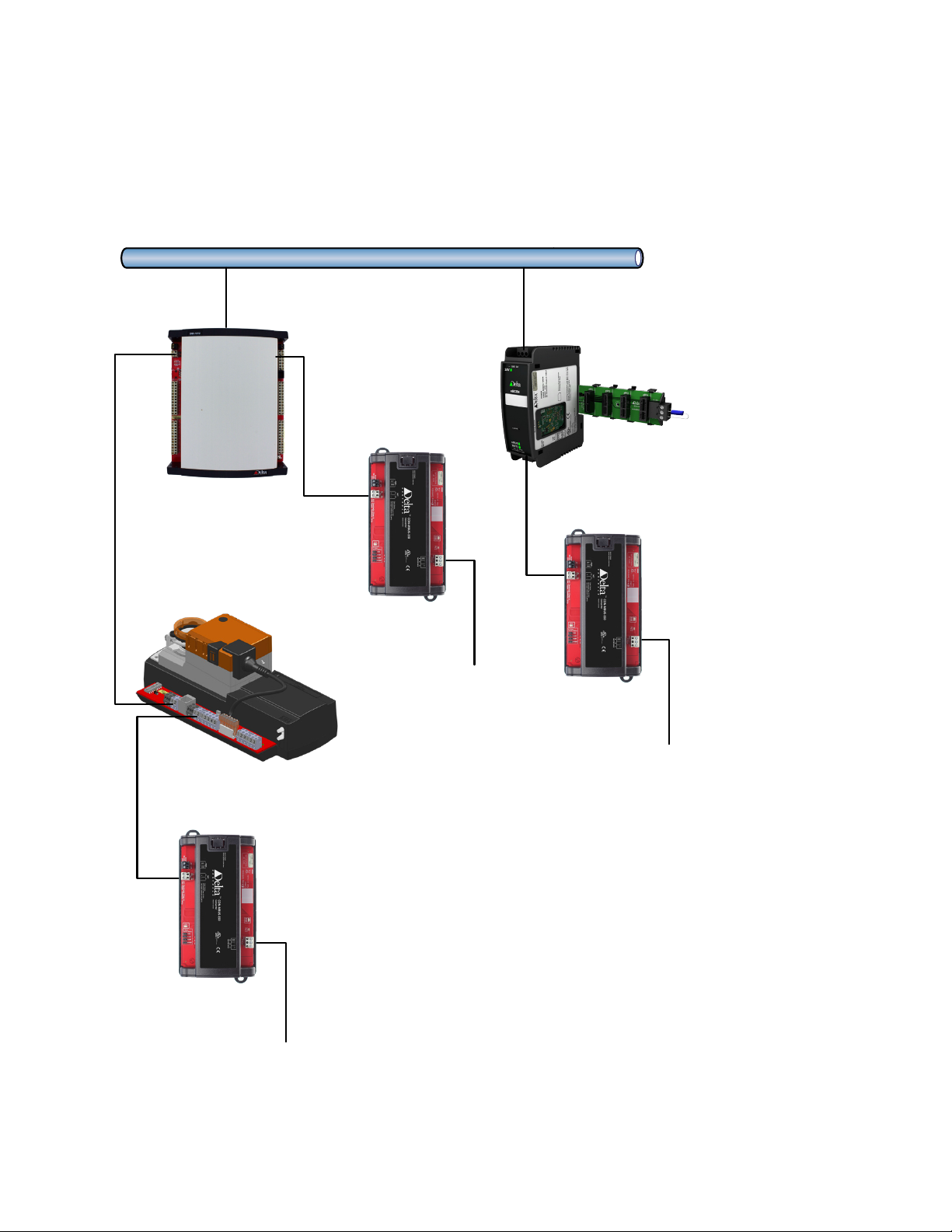
Typical Network Architecture with CON-MBUS
Ethernet
M-Bus network
Maximum 150 meters
M-Bus network
Maximum 150 meters
M-Bus network
Maximum 150 meters
CON-MBUS Application Guide Page 9 of 48
Document Edition 1.4
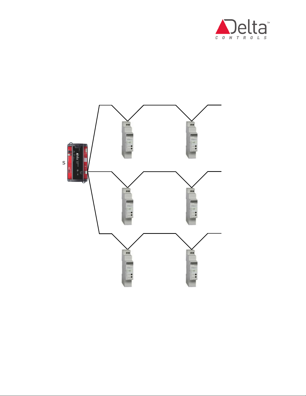
Example 1: Star M-Bus Network
Maximum Total Wire Length of all
network segments combined is
1000 m (3280 ft)
Maximum length of
each network segment is
350 m (1148 ft)
Network
Segment
CON-MBUS Network
Segment
Network
Segment
Typical Network Architecture with CON-MBUS
Page 10 of 48 CON-MBUS Application Guide
Document Edition 1.4
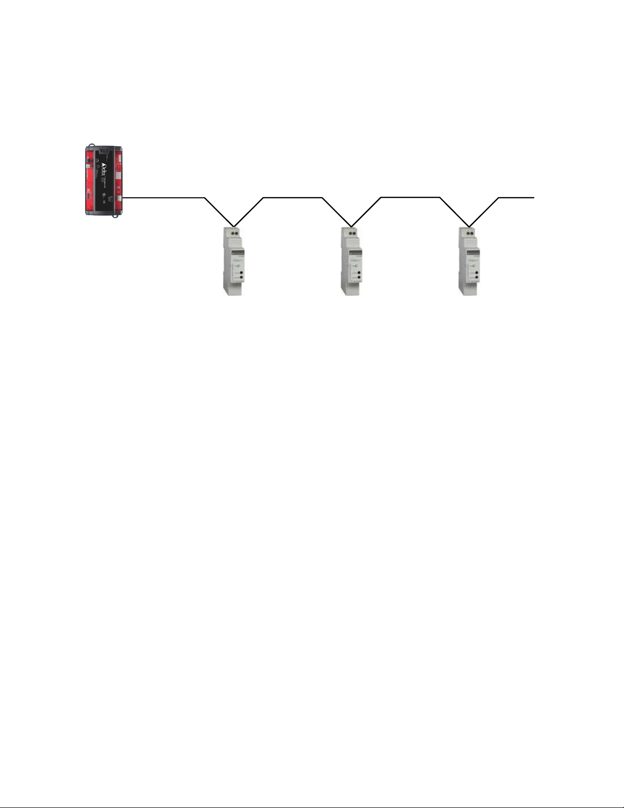
Example 2: Daisy Chain M-Bus Network
CON-MBUS
Network
Segment
Maximum Total Wire Length of all
network segments combined is
1000 m (3280 ft)
Maximum length of each network segment is
350 m (1148 ft)
Network
Segment
Network
Segment
Network
Segment
CON-MBUS Application Guide Page 11 of 48
Document Edition 1.4
Principles of Operation
The CON-MBUS allows you to collect multiple types of data from M-Bus meters wired to an
Delta installation.
The CON-MBUS Solution consists of the following components:
•Delta enteliBUS, DSC or DAC controller
•Custom Delta Gateway object and Gateway Translation objects residing in the Delta
controller
•CON-MBUS converter handles M-Bus communication
•Up to 150 M-Bus meters, depending on CON-MBUS product model being used
The Delta controller and objects translate data passed through the CON-MBUS from the M-
Bus meters . The data is represented as BACnet objects in the BACnet network.
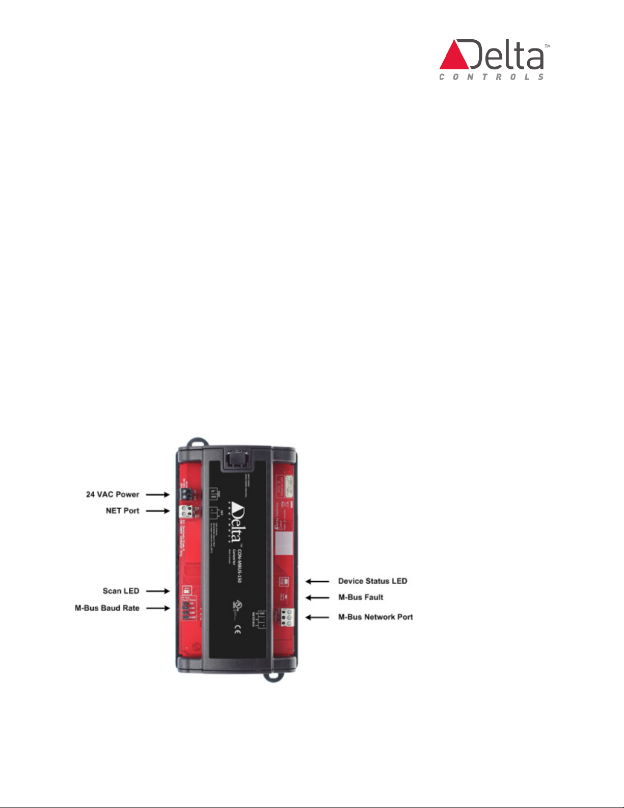
CON-MBUS Product Layout

Principles of Operation
Page 12 of 48 CON-MBUS Application Guide
Document Edition 1.4
See the CON-MBUS Status Indicators Table for information of the LED function.
Power over M-Bus Network
The CON-MBUS can supply power to meters over the M-Bus network. The CON-MBUS can
power up to 150 meters that each use 1 unit load of power. A unit load is equivalent to 1.5 mA.
Some meters use more than 1 unit load and this affects the total number of the meters that
can be powered.
When the total power consumption for the connected meters exceeds the 150 unit loads limit
of the CON-MBUS, then the M-Bus Fault LED is illuminated.
For detailed information about power over the M-Bus network, see the CON-MBUS Installation
Guide which is found on the CON-MBUS product page on George.
Supported M-Bus Meters
The CON-MBUS can support any meter that adheres to the M-Bus protocol standard. The
CON-MBUS product page on George downloadable GWT objects as POB files that are
configured for use with common M-Bus meters. It is much easier to use these GWT objects
rather than to create and configure new GWT objects.
Common M-Bus meters and manufacturers include:
•Sontex Supercal 531
•Sontex Supercal 539
•Siemens SITRANS FUE950
•Siemens UH50-A22c-AT06-F
•Apator LQM-III
•CALEC ST
•DHZ-NZR
•Schneider Electric iEM3135

CON-MBUS Application Guide Page 13 of 48
Document Edition 1.4
How to Integrate the CON-MBUS
The CON-MBUS is integrated into a Delta building automation system via an enteliBUS, DSC or
DAC controller. The DCU and enteliTOUCH do not support CON-MBUS integration.
Main Steps to Integrate the CON-MBUS
To integrate the CON-MBUS into a Delta building automation system, follow these main steps.
Each step is detailed in sections titled Step1 ..., Step 2... and so on. If you choose to download
GWT objects from the CON-MBUS page on the George site, then you would follow the first four
steps and then Step 6. These GWT objects are already configured for a specific product from a
manufacturer.
1. Upgrade the Delta controller with customized firmware that supports the wired CON-
MBUS.
2. Install the customized Gateway (GW) and Gateway Translation (GWT) object dialogs on
the ORCAview OWS.
3. Connect and configure the CON-MBUS converter using the GW object.
4. Add M-Bus meters to the network using GWT objects.
5. If using GWT objects from the CON-MBUS page on George (recommended approach).
Configure the GWT object to translate data in the meter's data packet.
6. If creating your own GWT object: Configure the GWT object to translate data in the
meter’s data packet.
7. Configure BACnet objects corresponding to the meter data.
Step 1: Upgrading the Delta Controller with Customized
Firmware
Customized firmware is required to enable CON-MBUS converter integration. See the CON-
MBUS page on George for this firmware. Use Flash Loader or System Loader to upgrade the
controller firmware.
When the firmware upgrade is completed, the controller database contains the CON-MBUS
Interface (GW1) object.

How to Integrate the CON-MBUS
Page 14 of 48 CON-MBUS Application Guide
Document Edition 1.4
Step 2: Installing the Customized Object Dialogs on OWS
In Version 3.33 you need to install the customized Gateway Translation (GWT) object dialog.
In Version 3.40, you need to install both the customized Gateway (GW) object and the Gateway
Translation (GWT) object dialogs.
Download the customized dialogs as POB files from the CON-MBUS support page on the
George support site.
After the required customized dialog(s) has been downloaded and saved as described in
following sections, restart the OWS for the changes to take effect.
Saving the customized GWT dialog for Version 3.33
For Version 3.33 the dialog is saved to:
C:\Program Files\Delta Controls\3.33\Dialogs\Vendor8\DAC
For Version 3.33 (64 bit Windows), the dialog is saved to:
C:\Program Files (x86)\Delta Controls\3.33\Dialogs\Vendor8\DAC
You may need to rename the dialog file; the required name after download is: vn8dacv3gwt.dlg
Saving the customized GWT and GW dialogs for Version 3.40
For Version 3.40 the two dialogs are saved to:
•Windows 7/Vista – C:\Users\Public\Delta Controls\3.40\Dialogs\Vendor8\DAC
•Windows XP – C:\Documents and Settings\Public\Delta
Controls\3.40\Dialogs\Vendor8\DAC
You may need to rename the dialog files; the required names after download are:
VN8dacv3gwt.dlg and VN8dacv3gw.dlg

CON-MBUS Application Guide Page 15 of 48
Document Edition 1.4
Step 3: Connecting and Configuring the CON-MBUS
The CON-MBUS is wired to a Delta controller via RS-485 cabling. See the CON-MBUS
Installation Guide on George for more information about this connection.
The two objects used to configure the M-Bus interface are the Gateway (GW) object and the
Gateway Translation (GWT) object. Each meter has a corresponding GWT object that contains
the configuration information needed to extract data from that meter.
The GW object:
•Enables / disables the interface
•Sets the Port as NET1 or NET2
•Sets the Baud rate (must be 38400 and this is the speed between the controller and
the CON-MBUS)
•Provides diagnostic statistics about communications
•Provides a way to change the primary meter address from an old to a new value
(e.g. From 1 to 5).
The GWT object:
•Provides Scan Counter (counts down the Scan Timer) and Reliability fields
•Defines the Scan Timer in the first row in the table.
•Provides a table that holds a list of row entries that define the data to get from the
M-BUS meter.
•Creates BACnet objects as data destinations for each Page #, Record #, and
Multiplier entry. See the About the GWT object translation programming fields
section for more information.

How to Integrate the CON-MBUS
Page 16 of 48 CON-MBUS Application Guide
Document Edition 1.4
To configure the CON-MBUS:
1. From ORCAview, open the CON-MBUS Interface (GW1) object and select the Setup tab.
In the Port Settings section, set Port to the one that the CON-MBUS is connected to. The
default is NET2. Reset the device after saving the GW1 settings if you choose to use
NET1.
2. Ensure that the Speed of the port is set to 38,400. The CON-MBUS requires this 38,400
baud rate. The default speed is 38,400 baud in the GW object. Click Apply.
To verify that the CON-MBUS is communicating with the controller, select the Statistics
tab and wait a few moments. A Total Received value greater than zero indicates proper
communications is established. The main indication of initial communication is that the
Total Received is greater than zero with lesser emphasis on the Sent failures which
may be a large number. The CON-MBUS does not send messages itself, it only receives
them. It is the received packets that are of interest.
Ignore the dialog Header area when confirming communications with the CON-MBUS.
In the Version 3.33 GW object dialog, you may see No Data Received; this is not
relevant.
3. Click OK.

CON-MBUS Application Guide Page 17 of 48
Document Edition 1.4
Step 4: Adding a Meter to the Network
Before you can add an M-Bus meter to the wired network, you need to know the address of the
M-BUS meter. The primary address can be obtained in either of two ways described in the
Obtaining the primary meter address topic later in this section.
Role of the Gateway Translation object
The CON-MBUS uses custom Gateway Translation (GWT) objects to represent the M-BUS
meter. One GWT object represents one meter. Up to 150 GWT objects and therefore 150
meters, can be created on the controller per CON-MBUS.
A GWT object represents all data elements available from one wired meter. For example, a
meter could have the following information:
•Temperature
•Flow
•Volume
The GWT object in this case contains three entries, one for each data element. Corresponding
BACnet objects are created in the Delta controller for each entry to expose the data.
Obtaining the primary meter address
There are multiple approaches to obtain the address:
•Check documentation with meter for address information. A new meter from the
factory generally has a primary meter address of 0.
•Display the information on the LCD screen of the meter. Consult meter
documentation for the procedure.
•Use a third party optical interface with software to get the meter information.
•With one meter connected to the CON-MBUS, enter a meter number and check for
communication. Check the Description tab of the GWT objects for information such
as the Meter ID#. This guess and check approach is the least preferred one.
How to Integrate the CON-MBUS
Page 18 of 48 CON-MBUS Application Guide
Document Edition 1.4
To obtain a Meter ID from a meter.
The best approach is to identify the meter in the field. The GW object shows meter information
such as the Meter ID# for a specific meter, while a GWT shows the specified number of records
for the GWT where the GWT instance corresponds to the primary address.
1. Open the gateway GW object in the controller and select the Description tab.
2. Create a GWT object with an instance number that corresponds to the primary meter
address (e.g. GWT4 for a meter with a primary address of 4).
3. Open the GWT object.
4. On the Setup tab, add the following entry.
The entry in the first row defines the Scan Timer value. In a typical application, this
value is typically 20 seconds or longer. As more meters are connected, then the Scan
Timer value may require an increase.
5. Click Apply.
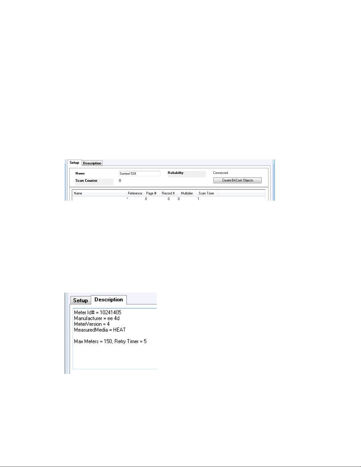
6. Wait for the information to display in the Description tab of the GWT object. You may
have to wait for 10 or more seconds.
The meter transmits identification information which is displayed in the GWT object
dialog’s Description tab. Determine the Meter ID# from this information. In the
example below, the Meter Id# is 10241505.
If the information is not displayed, this may be because the meter is already
represented by a GWT object. To confirm that the meter is transmitting, observe the
LEDs in the CON-MBUS and also the M-Bus meter. The presence of information in the
Description tab of the GWT confirms that the meter is communicating.

CON-MBUS Application Guide Page 19 of 48
Document Edition 1.4
Creating the GWT object and adding a meter to the network
A new meter from the factory generally has a primary address of 0. Change the address by
going to the Programming tab on the GW object.
Addressing a Meter
To change the primary address of a M-BUS meter:
1. Open the Programming tab on the GW object.
2. Enter the Old Address and a New Address. Click Change Meter Address.
3. Click Apply.
To add a meter to the network:
1. Create a Gateway Translation (GWT) object to represent the meter. There are two
methods for getting a GWT object, described below as method A and method B:
A. Obtain the GWT object from the CON-MBUS page on George and load it into the Delta
controller. Using GWT objects from this George page is the recommended
approach. These objects are already configured by Delta for the data elements
available from the meter, which saves you the time.
B. Use ORCAview to create a GWT object to represent the meter.
2. Open the GWT object dialog and select the Setup tab.

How to Integrate the CON-MBUS
Page 20 of 48 CON-MBUS Application Guide
Document Edition 1.4
3. If necessary, create an entry in the first row that defines the Scan Timer. Leave the
name field blank. Enter * in the reference field. Enter a value, 1 second or higher in the
Scan Timer column. Enter 0 in the Page #, Record #, and Multiplier fields of the first
row entry.
A Scan Timer of 0 seconds gets the record information once and does not update it. If a
Scan Timer of 1 second. was used, the information would update frequently making it
difficult to read.. After this operation, change the Scan Timer to an acceptable value
such as 20 or 30 seconds.
4. Wait for the meter to transmit a message and observe that, in a few seconds, the
Reliability field displays Connected. A Reliability field equal to Connected confirms that
you have added the meter to the network successfully.
To verify that you are indeed causing the meter to transmit a message, observe the
LEDs in the CON-MBUS: when a meter transmits a message, the amber LEDs
illuminate briefly. This approach is only valid with a few meters connected but is not
useful with many meters connected, as the LEDs blink all the time.
5. Click OK to save and close.
Set GCL Wait Time for Meter Queries
The Setword6 property allows you to set a retry timeout for querying meters. Adding wait time
before a query allows for slower meters, for example, some Apator meters. The CON-MBUS
sends the query to the meter three times but some meters need more time to respond.
The Setword6 property affects the retry timeout for all meters on the MBUS network.
In a GCL program, you manipulate the following Gateway object property:
700.GW1.setword6.value
The value has a range of 5 to 45 which corresponds to a retry timeout of 0.5 to 5 seconds.
Table of contents
Other Delta Controls Media Converter manuals

Popular Media Converter manuals by other brands


Linear Technology
Linear Technology LTC3129-1 manual

Transition Networks
Transition Networks E-TBT-FRL-FD-01 installation guide

pico Technology
pico Technology ADC-200 installation guide

ADF Web
ADF Web HD67411 user manual

Fuji Electric
Fuji Electric RHC-D 690V Series manual

Tektronix
Tektronix 7D12 Service instructions manual