DELTA DORE TYDOM 4000 User manual
GH
CED F
B
Ø 65 mm
Ø 65 mm
INPUT 100-240V~ 50-60 Hz 0,3A
OUTPUT : 9V 500 mA
119
174 3185
480 x 272
+++
++
+
+
A
A B E F
H
A B
A B C G
E
+
++++
++++
IP 30
868 MHz EN 300 220
100 - 300m
0°C +40°C
°C
D
D
x4
x4
E
B
EH
H
H
M3x20
M3x20
x4
M3,5x32
x4
M3,5x32
M3x8
M3x8
1
2
M3x8 EF
H
TYDOM
4000
230 V~
0,75 mm
?
i
31
1
2
3*
D
D
28
194,6 x 139,3
OFF
60 %
80 %
0 %
80 %
0 %
18.5 °C
OFF
OFF
OFF
RFID
6700042
INPUT 230V~ 50-60 Hz
OUTPUT 12V 1A
32 x 55 x 51 mm
1
DIN
6700041
INPUT 230V~ 50-60 Hz
OUTPUT 12V 0.8A
6700043
INPUT 230V~ 50-60 Hz
OUTPUT 13.8V 5A.
84 x 180 x 240 mm
0100%
i
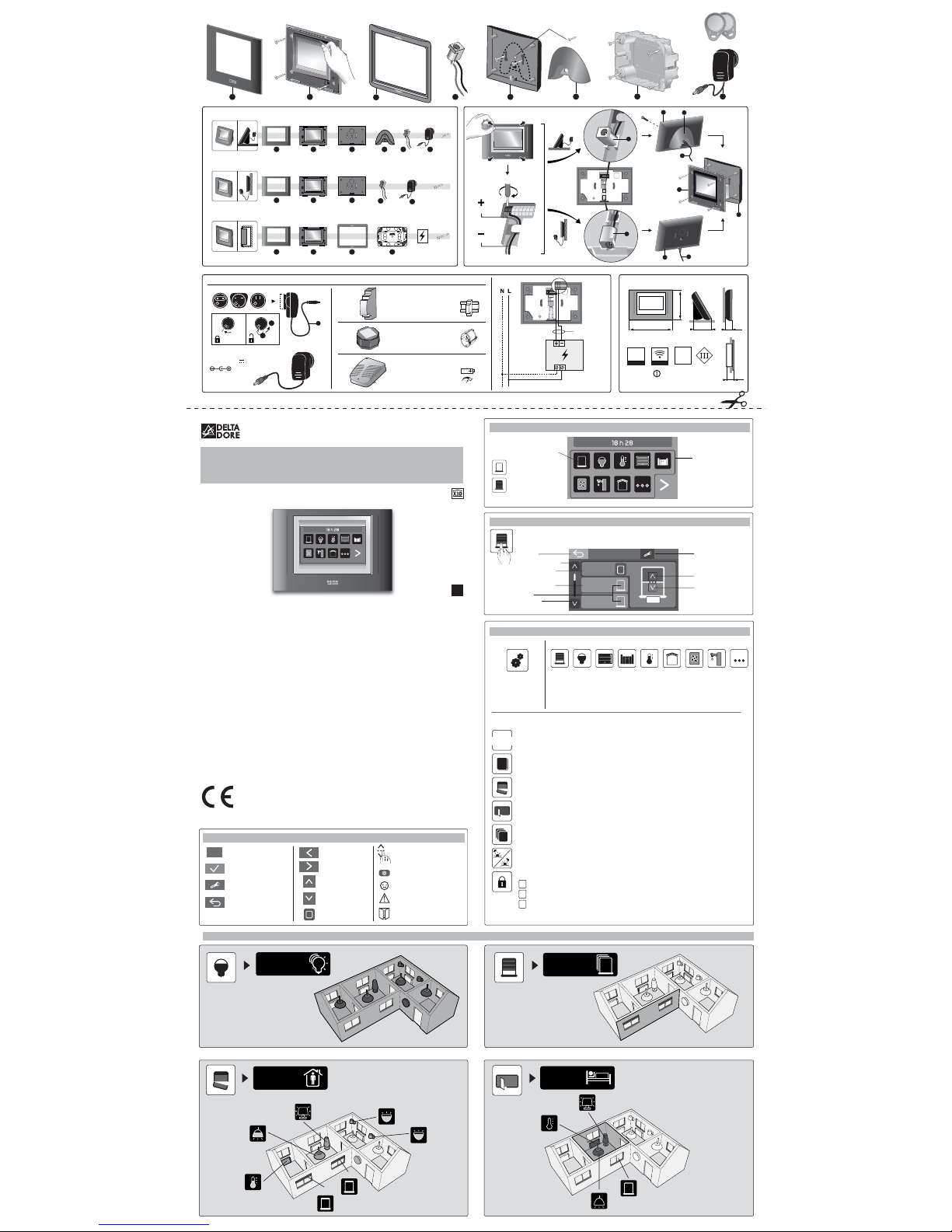
Installation instructions
1. The home page screen
2. The control screen
3. The touch screen buttons
Current function status
displayed
Example:
All shutters
are open
All shutters
are closed
Access to
features
You can access the wall terminal functions by touching the screen.
Press the function you require.
Back
Previous page
Control of all shutters
in the group
Shutter control 1
Current status
Next page
Shutters
Group
Total
Shutter 1
Shutter 2 Stop
Configuration
Raise
Lower
Configuration Functions
Button available
for access levels
2 and 3. (*)
Roller
shutters Lighting Garage Gate Other
uses
The various functions of your wall terminal enable you to:
• Create control groups,
• Add and delete products (access level 3).
N.B.: Functions that are not installed do not appear on the screen.
To get the most out of your wall terminal.
Progra
mProgramming:
Create a weekly program for the various functions installed.
Calendar: Select exceptional absence or presence periods.
These periods take priority over programming.
Scenarios: Combine actions selected for different functions:
Roller shutters, lighting, etc. (Away scenario: Shutters closed, lights off.
Arrival scenario: shutters open)
Management of controls by room:Group together controls for the same room.
(e.g. Lounge - 3lights - 2 roller shutters).
Management of controls by group:Group together controls with the same functions.
(e.g. all roller shutters on the ground floor).
Astronomical mode: Control the status of shutters and/or lighting based on sunrise
and sunset times.
3locking levels to protect your configuration (*)
Changes not allowed
Customisation of the buttons, scenarios and rooms
Addition and deletion of RF products possible
*Installer access code required
Delta Dore hereby declares
that the equipment meets the essential
requirements and complies with the other
relevant provisions of Directive 1999/5/EC
(R&TTE Directive) (radio)
Because of changes in standards and equipment,
the characteristics given in the text
and the illustrations in this document are not
binding unless confirmed
*2702965_Rev.1*
www.deltadore.com
4. Key to pictograms
Help display
Confirmation
Configuration
button
Back
Previous screen
(Holding the button down displays
the home page)
Next screen
Previous page
Next page
Swipe your finger
up or down
to increase or decrease
Pulse control
Information
Command executed
correctly
Fault warning
Group
Total
Arrival
South-facing
shutter group
Bedroom
Paul
TYDOM 4000
Wall terminal
User guide
EN
Red wire
Black wire
5. Applications
Open entry
Settings
Sat. 11 June
Shutters Lighting Heating and
Cooling Garages Gates
CMV
Domestic hot
water tank
Alarm Other uses
Heating and
Cooling Alarm CMV Domestic hot
water tank
Next
Optional
Types of power supply

18,5°C
ON OFF
ONOFF
Choose
number
Choose
wording
1234567
Add products
Delete all products
Yes
No Yes
No
Yes
No P2
P3
P4
P1
Yes
No
DateTime
New programName
Delete the step
Copy the day
Latitude Longitude Time zone
Morning shift
Language
Summer/winter
time
Time format
Date format
Access level
Installer access
code
Associate asensor
Delete the sensor
Create aprogramCreate
product list
Rooms
Calendar
Settings
Program
Select the
application
Astronomical
mode
Parameters
Advanced
settings
31
Brightness
Time/Date
Regional
parameters
Software
versions
Name Choose
pictogramSelect
products
Name
Select
program
Name Choose
pictogram
Presence
Choose
standard dayChoose actions
Absence
Select
productsSelect
statuses
Add products
Delete
products
Delete
all products
Programming
Programming
Delete group
Lock
Outdoor
sensor
Network
maintenance
Touch screen
Badge
Alarm
initialisation
Factory
initialisation
Yes
No
Evening shift Sunrise limit Sunset limit
Operation
Manual
24h
AM/PM
dd/mm/yy
mm/dd/yy
No
Manage
product list
Name
Choose
pictogram
Modify statuses
Delete
the scenario
Manage
product list
Name
Choose
pictogram
Add
detector
Name
List of
detectors
Name Choose
pictogramSelect products
Delete the room
Manage
product list
Name
Choose
pictogram
Delete
all products
Delete
aproduct
Add products
Pre-defined
wording
Customised
wording
1110 12 139 43 5
1817 19
11
11
Green: Presence
Red: Absence
11 Black: Auto
Next month
Previous month
1
* * * *
User access
code * * * *
2 3
132 4
1
116
1
2
5
4
3
1
2
3
Choose
pictogram
Locate
?
Program 1 Name
Change
program
Manage
product list
Delete program
12
ON
< 20 sec
1 2 3 4
1 2 3 4 * * * *
RESET
RESET
NEW NEW X2
* * * *
17 32
12
?
230V~
50/60 Hz
ON
1sti
1 2 3 4
OK
OFF OFF
OFF OFF
> 3"
1 2
... ... ...
230V~
50/60 Hz
ON
12
34
Delete the step
Copy the day
External actions
OFF
Bip
ON OFF
21
i
New group
Group total
Group 1
Point 2
Scenarios
New scenario
Scenario 1
New room
Pièce 1
OFF
Manage
the productsGroup total
Point
Automatic
mode
Manage
the partials
Warning
device test
Download
Add badges
Delete badges
Delete
all badges
Group total
*
*
*
*
Choose an element from the list or press the associated product'stest button.
OFF
1 2
ON
ON i
Alarm
OFF
After configuration is complete, it is a good idea to customise your installer access code.
Protect your configuration by choosing an appropriate access level (level 1 or 2 recommended)
You can visit the help section for the displayed page at any time by pressing this symbol.
6. Configuration
7. Block diagram
Language
selection Date setting Time setting
Start
Locate
Advanced
settings Lock Installer access
code
Advanced
settings Lock Access level
Changes not allowed during use
Customisation of the buttons, scenarios and rooms
Addition and deletion of RF products possible
Installer access
code Continue
The Heating and Cooling function control screen
Back
Product batteries low
Configuration
Information
Fault warning
Open entry
Alarm status
On Off
Partial Partial
Surveillance
activated
Partial
operation modes
Badge detection zone
Surveillance switched off
Alarm
The Heating and Cooling function control screen
Back
Previous page
General control
Setting 1 Control
Pilot Wire 1 Control
Next page
Configuration
Current status
General
Setting 1
18.5 °C
Pilot Wire 1
Set back
Heating
Off
AC
Off mode
Air conditioning mode
Setting Pilot wire On-Off
Set back Off
Heating and Cooling
Cancel
Programming
override
Adjustment by setting
°C Adjustment by mode On-Off selection
Heating Mode
3 types of control depending on your installation
Name
(default)
(default)
Menu
“Add
a product”
Alarm
(default)
Choose a pictogram
YES NO
Table of contents


