HD2402 - 11 - V1.4
3OPERATING PRINCIPLE
6 sensors are used for the measurement of optic radiations. Each sensor covers a giv-
en spectral range and measurements in conformity with L.D. 81/08 can be performed
through the combination of signals coming from several sensors. The sensors used are
photodiodes, except for channel 9 that utilizes a thermopile sensor.
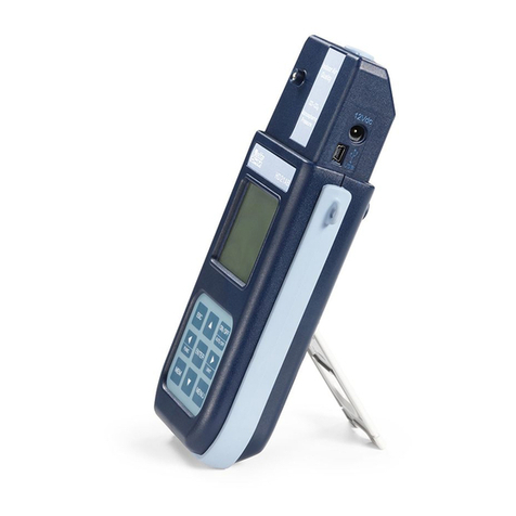
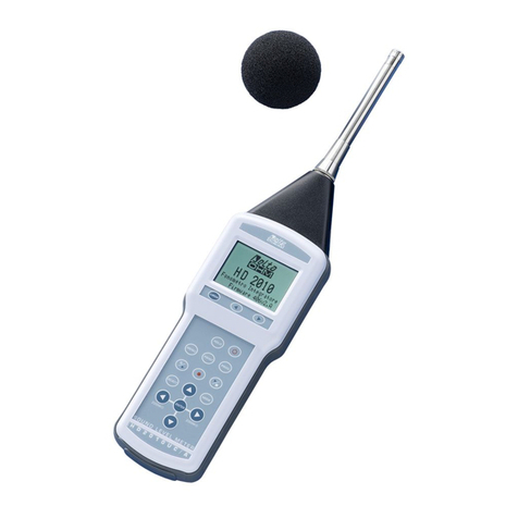
The instrument is provided with a pointing LASER to indicate to the user the area out-
lined by the instrument. The LASER is switched on by means of the button on the rear
of the instrument. By pressing the button, the LASER is switched on for 10 seconds.
HD2402 is powered through the USB cable, when it is connected to a PC. The red indi-
cator on the back of the instrument shows that the instrument is properly powered.
Table 2 lists all channels available in the instrument with their spectral range and cor-
responding spectral weighting curve (V[λ], S[λ], B[λ], R[λ]), implemented through the
use of appropriate filters.
Channel Measure quantity Spectral range and corre-
sponding weighting curve Sensor type
6 Illuminance [Lux]
380nm÷780nm; V[λ] Photodiode + Filter
2 Irradiance [W/m2] 220nm÷400nm; S[λ] Photodiode + Filter
5 Irradiance [W/m2] 315nm÷400nm; UVA Photodiode + Filter
7 Irradiance [W/m2] 400nm÷600nm; B[λ] Photodiode + Filter
3 Irradiance [W/m2] 660nm÷1300nm; R[λ] Photodiode + Filter
9 Irradiance [W/m2] 400nm÷3000nm Thermopile
Table 2: measurement channels available in the instrument
Processing of the sensor output signal is handled independently for each channel and
in different modes.
Transimpedance amplifiers are used for channels 3, 5 and 6. Signal is acquired 1000
times per second. Both the average value per second and the peak signal of the 1000
samples acquired is displayed by the software. The amplifiers have 4 scales each, that
are independent of the other. Scale change is automatic or manual.
Channels 2 and 7 use a charge integrator. The integration time depends on the required
sensitivity, ranging from 1 ms in the low sensitivity scale to 1 second in the full sensitiv-
ity scale (there are 4 scales, that are independent for the two channels). Also in this
case, the instrument displays the mean value per second and the peak signal of the ac-
quired samples (in the full sensitivity scale, when the integration time is 1 second,
mean value and peak value coincide). The scale change is automatic or manual.
Channel 9 is a power amplifier. There is only 1 scale. In this case, only the mean val-
ue is displayed, since the response time of the sensor is of about 9 seconds.
Table 3 shows the full scale values available for each channel:
Channel


