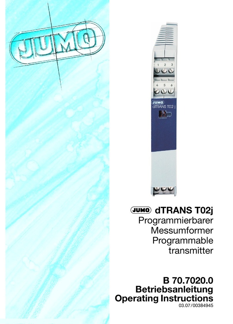
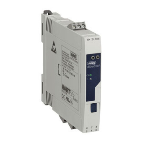
JUMO dTRANS T07 User manual

V4.00/EN/00681575
Page 1/28Data Sheet 707080
-802*PE+&R.*
'HOLYHU\DGGUHVV 0DFNHQURGWVWUDH
)XOGD*HUPDQ\
3RVWDODGGUHVV
)XOGD*HUPDQ\
3KRQH
)D[
(PDLO PDLO#MXPRQHW
,QWHUQHW ZZZMXPRQHW
-802,QVWUXPHQW&R/WG
-802+RXVH
7HPSOH%DQN5LYHUZD\
+DUORZ(VVH[&0'<8.
3KRQH
)D[
(PDLO VDOHV#MXPRFRXN
,QWHUQHW ZZZMXPRFRXN
-8023URFHVV&RQWURO,QF
0\HUV5RDG
(DVW6\UDFXVH1<86$
3KRQH
)D[
(PDLO LQIRXV#MXPRQHW
,QWHUQHW ZZZMXPRXVDFRP
70708000T10Z001K000
JUMO dTRANS T07
Two-channel temperature transmitter with HART/Ex/SIL
for installation into terminal head form B and for installation on DIN rail
Brief description
The JUMO dTRANS T07 device series is a two-channel temperature transmitter with HART1
communication. The devices are available in 2 versions: for installation in a B-head or for DIN-
rail mounting. The variants with Ex and SIL approval (IEC 61508) for SIL 2/3 (hardware/software)
enable secure use in demanding process applications.
The configurable transmitters transmit converted signals from RTD temperature probes and ther-
mocouples (TC) as well as from resistor and voltage sensors to the galvanically isolated
4 to 20 mA current output. Internal sensor monitoring functions and device error detection en-
able a high degree of measuring point availability.
The optional plug-on display BD7 can be used to display the current measured value on the B-
head variant.
The JUMO dTRANS T07 device series is tailor-made for all industries like chemicals, oil, gas,
and power plants & energy, as well all others in which safe and reliable temperature measure-
ments are required.
1HART® is a registered trademark of the FieldComm Group™
Type 707080 (dTRANS T07 B)
Type 707082 (dTRANS T07 T)
Block diagram
Transmitter
Voltage supply
Voltage sensor
+
-
RTD
Temperature probe
Resistor/Potentiometer
Input signals
Version for B-head:
DC 11 to 42 V
4 to 20 mA
Output signal
Communication
HART communication
for configuration and diagnosis
(HART 7 protocol)
TC
Thermocouple
Version for DIN rail:
DC 12 to 42 V
Special features
• Two universal measurement inputs
(RTD, TC, Ω, mV)
• High degree of accuracy
(0.1 K with Pt100 sensor)
• Output 4 to 20 mA
(single channel, loop powered)
• Two enclosure versions
(B-head or DIN rail)
• HART 7 protocol
with extension for "secure HART"
• SIL 2/3 hardware/software
according to IEC 61508
• Reliable measurement operation
through sensor monitoring and
device hardware error detection
• Optional plug-on display BD7
for B-head device version
Approvals/approval marks (see "Technical data")

V4.00/EN/00681575
Page 2/28Data Sheet 707080
-802*PE+&R.*
'HOLYHU\DGGUHVV 0DFNHQURGWVWUDH
)XOGD*HUPDQ\
3RVWDODGGUHVV
)XOGD*HUPDQ\
3KRQH
)D[
(PDLO PDLO#MXPRQHW
,QWHUQHW ZZZMXPRQHW
-802,QVWUXPHQW&R/WG
-802+RXVH
7HPSOH%DQN5LYHUZD\
+DUORZ(VVH[&0'<8.
3KRQH
)D[
(PDLO VDOHV#MXPRFRXN
,QWHUQHW ZZZMXPRFRXN
-8023URFHVV&RQWURO,QF
0\HUV5RDG
(DVW6\UDFXVH1<86$
3KRQH
)D[
(PDLO LQIRXV#MXPRQHW
,QWHUQHW ZZZMXPRXVDFRP
70708000T10Z001K000
Type overview
Operating mode
The temperature transmitters in the dTRANS T07 series are two-wire transmitters with two measurement inputs and one analog output.
The devices transmit both converted signals from RTD temperature probes and thermocouples, but also resistance and voltage signals via the
HART communication and as a 4 to 20 mA current signal.
They can be installed as intrinsically safe equipment in potentially explosive areas and serve primarily for instrumentation in the form B terminal
head in accordance with DIN EN 50446 or as a DIN rail device for installation in the control cabinet on a TH 35 DIN rail in accordance with
DIN EN 60715.
Application examples
Type Designation Description
707080 dTRANS T07 B For installation in terminal head, form B
707081 dTRANS T07 B SIL For installation in terminal head, form B, with SIL approval
707082 dTRANS T07 T For mounting on DIN rail
707083 dTRANS T07 T SIL For mounting on DIN rail, with SIL approval
707085 dTRANS T07 B Ex For installation in terminal head, form B, with Ex approval
707086 dTRANS T07 B EX SIL For installation in terminal head, form B, with Ex and SIL approval
707087 dTRANS T07 T Ex For mounting on DIN rail, with Ex approval
707088 dTRANS T07 T Ex SIL For mounting on DIN rail, with Ex and SIL approval
Example 1:
Two sensors with measurement input (RTD or TC) in remote installation
on a DIN rail device with the following advantages: drift warning, sensor
backup function and temperature-dependent sensor switching
Example 2:
Integrated transmitter in the terminal head – 1 x RTD/TC or 2 x RTD/TC
as redundancy
RTD/TC RTD/TC
dTRANS T07
1× RTD/TC /
2× RTD/TC

V4.00/EN/00681575
Page 3/28Data Sheet 707080
-802*PE+&R.*
'HOLYHU\DGGUHVV 0DFNHQURGWVWUDH
)XOGD*HUPDQ\
3RVWDODGGUHVV
)XOGD*HUPDQ\
3KRQH
)D[
(PDLO PDLO#MXPRQHW
,QWHUQHW ZZZMXPRQHW
-802,QVWUXPHQW&R/WG
-802+RXVH
7HPSOH%DQN5LYHUZD\
+DUORZ(VVH[&0'<8.
3KRQH
)D[
(PDLO VDOHV#MXPRFRXN
,QWHUQHW ZZZMXPRFRXN
-8023URFHVV&RQWURO,QF
0\HUV5RDG
(DVW6\UDFXVH1<86$
3KRQH
)D[
(PDLO LQIRXV#MXPRQHW
,QWHUQHW ZZZMXPRXVDFRP
70708000T10Z001K000
Functions
Standard diagnostic functions
• Wire breakage, short-circuit of the sensor lines
• Wiring faults
• Internal device errors
• Measuring range exceeded (too high or too low)
• Ambient temperature limits exceeded (too high or too low)
Corrosion detection in accordance with NAMUR NE89
Corrosion of sensor connection wires can falsify the measured values. The transmitters offer the option of detecting corrosion on thermocouples
and RTD temperature probes with four-wire connection before the measured values are affected. The transmitters prevent incorrect measured
values from being read out and can output a warning via the HART protocol if conductor resistances exceed plausible limits.
Undervoltage detection
The undervoltage detection prevents the continuous output of an incorrect analog output value by the devices (due to damaged or incorrect voltage
supply or due to a damaged signal cable). If the voltage drops below the minimum required voltage supply then the analog output value drops for
approx. 5 s to < 3.6 mA. Afterwards the devices attempt to output the normal analog output value again. If the voltage supply is still too low, this
process is repeated cyclically.
Two-channel functions
These functions increase the reliability and availability of the measured values:
• The sensor backup switches to the second sensor if the primary sensor fails.
• Drift warning or alarm if the deviation between sensor 1 and sensor 2 is less than or greater than a defined limit value.
• Temperature-dependent switching between sensors that are used in different measuring ranges.
• Average value measurement or differential measurement from two sensors.
• Average value measurement with sensor redundancy
Not all modes are available for SIL operation SIL safety manual for dTRANS T07 series (SIL designs).

V4.00/EN/00681575
Page 4/28Data Sheet 707080
-802*PE+&R.*
'HOLYHU\DGGUHVV 0DFNHQURGWVWUDH
)XOGD*HUPDQ\
3RVWDODGGUHVV
)XOGD*HUPDQ\
3KRQH
)D[
(PDLO PDLO#MXPRQHW
,QWHUQHW ZZZMXPRQHW
-802,QVWUXPHQW&R/WG
-802+RXVH
7HPSOH%DQN5LYHUZD\
+DUORZ(VVH[&0'<8.
3KRQH
)D[
(PDLO VDOHV#MXPRFRXN
,QWHUQHW ZZZMXPRFRXN
-8023URFHVV&RQWURO,QF
0\HUV5RDG
(DVW6\UDFXVH1<86$
3KRQH
)D[
(PDLO LQIRXV#MXPRQHW
,QWHUQHW ZZZMXPRXVDFRP
70708000T10Z001K000
Technical data
Analog input
General information
RTD temperature probe
Resistance/potentiometer (Ω)
Measurand Temperature (temperature-linear transmission behavior), resistance and voltage.
Measuring range It is possible to connect two mutually independent sensors.a.
The measurement inputs are not galvanically isolated from each other.
aWith a 2-channel measurement, the same measurement unit must be configured on both channels (e.g. both °C, °F, or K). Mutually independent
2-channel measurement of resistance/potentiometer (ohm) and voltage sensor (mV) is not possible. In this case, either both channels must be
configured to "ohm" or both channels must be configured to "mV" .
Standard DesignationaαMeasuring range limits Minimum
measuring
span
IEC 60751:2008
Pt100 (1)
0.003851 K-1
-200 to +850 °C
10 K
Pt200 (2) -200 to +850 °C
Pt500 (3) -200 to +500 °C
Pt1000 (4) -200 to +250 °C
JIS C1604:1984 Pt100 (5) 0.003916 K-1 -200 to +510 °C 10 K
DIN 43760 IPTS-68 Ni100 (6) 0.006180 K-1 -60to+250°C 10 K
Ni120 (7) -60 to +250 °C
GOST 6651-94 Pt50 (8) 0.003910 K-1 -85to+1100°C 10 K
Pt100 (9) -200 to +850 °C
OIML R84: 2003,
GOST 6651-2009
Cu50 (10) 0.004280 K-1 -180 to +200 °C
10 K
Cu100 (11) -180 to +200 °C
Ni100 (12) 0.006170 K-1 -60to+180°C
Ni120 (13) -60 to +180 °C
OIML R84: 2003,
GOST 6651-94 Cu50 (14) 0.004260 K-1 -50 to +200 °C 10 K
-
Pt100 (Callendar–Van
Dusen)
nickel polynomial
copper polynomial
-The measuring range limits are defined by entering the limit
values, which depend on the coefficients A to C and R0. 10 K
• Connection type: two-wire, three-wire or four-wire connection, sensor current: ≤ 0.3 mA
• On a two-wire circuit compensation for the wire resistance is possible (0 to 30 Ω)
• On three-wire and four-wire connections: sensor wire resistance of up to 50 Ω max. per wire
aThe digits after the designations are used to clarify distinctions, e.g. for distinguishing the same sensors on the basis of different standards.
They are also used for configuration and safe parameterization of the transmitter.
Standard Designation αMeasuring range limits Minimum
measuring
span
- Resistance (Ω) - 10 to 400 Ω 10 Ω
10 to 2000 Ω 10 Ω

V4.00/EN/00681575
Page 5/28Data Sheet 707080
-802*PE+&R.*
'HOLYHU\DGGUHVV 0DFNHQURGWVWUDH
)XOGD*HUPDQ\
3RVWDODGGUHVV
)XOGD*HUPDQ\
3KRQH
)D[
(PDLO PDLO#MXPRQHW
,QWHUQHW ZZZMXPRQHW
-802,QVWUXPHQW&R/WG
-802+RXVH
7HPSOH%DQN5LYHUZD\
+DUORZ(VVH[&0'<8.
3KRQH
)D[
(PDLO VDOHV#MXPRFRXN
,QWHUQHW ZZZMXPRFRXN
-8023URFHVV&RQWURO,QF
0\HUV5RDG
(DVW6\UDFXVH1<86$
3KRQH
)D[
(PDLO LQIRXV#MXPRQHW
,QWHUQHW ZZZMXPRXVDFRP
70708000T10Z001K000
Thermocouples (TC)
Voltage sensor (mV)
Connection combinations
If both sensor inputs are assigned then the following connection combinations are possible:
Standard DesignationaMeasuring range limits Minimum
measuring
span
Possible temperature range Recommended tempera-
ture range
IEC 60584, part 1
Type A (W5Re-W20Re) (30) 0 to +2500 °C 0 to +2500 °C 50 K
Type B (PtRh30-PtRh6) (31) +40 to +1820 °C +500 to +1820 °C 50 K
Type E (NiCr-CuNi) (34) -270 to +1000 °C -150 to +1000 °C 50 K
Type J (Fe-CuNi) (35) -210 to +1200 °C -150 to +1200 °C 50 K
Type K (NiCr-Ni) (36) -270 to +1372 °C -150 to +1200 °C 50 K
Type N (NiCrSi-NiSi) (37) -270 to +1300 °C -150 to +1300 °C 50 K
Type R (PtRh13-Pt) (38) -50 to +1768 °C +50 to +1768 °C 50 K
Type S (PtRh10-Pt) (39) -50 to +1768 °C +50 to +1768 °C 50 K
Type T (Cu-CuNi) (40) -260 to +400 °C -150 to +400 °C 50 K
IEC 60584, part 1
ASTM E988-96 Type C (W5Re-W26Re) (32) 0 to +2315 °C 0 to +2000 °C 50 K
ASTM E988-96 Type D (W3Re-W25Re) (33) 0 to +2315 °C 0 to +2000 °C 50 K
DIN 43710 Type L (Fe-CuNi) (41) -200 to +900 °C -150 to +900 °C 50 K
Type U (Cu-CuNi) (42) -200 to +600 °C -150 to +600 °C 50 K
GOST R8.8585-2001 Type L (NiCr-CuNi/Chromel-Co-
pel) (43)
-200 to +800 °C -200 to +800 °C 50 K
-
• Internal cold junction (Pt100)
• External cold junction: adjustable value from -40 to +85 °C
• Maximum sensor wire resistance 10 kΩ (if the sensor wire resistance is greater than 10 kΩ then an error mes-
sage will be output in accordance with NAMUR NE89)
aThe digits after the designations are used to clarify distinctions, e.g. for distinguishing the same sensors on the basis of different standards.
They are also used for configuration and safe parameterization of the transmitter.
Standard Designation αMeasuring range limits Minimum
measuring
span
- Millivolt sensor (mV) - -20 to 100 mV 5 mV
Sensor input 1
RTD or resistance/potenti-
ometer, two-wire
RTD or resistance/potenti-
ometer, three-wire
RTD or resistance/potenti-
ometer, four-wire
Thermocouple (TC), volt-
age sensor
Sensor input 2
RTD or resistance/potenti-
ometer, two-wire
RTD or resistance/potenti-
ometer, three-wire
RTD or resistance/potenti-
ometer, four-wire
Thermocouple (TC), volt-
age sensor

V4.00/EN/00681575
Page 6/28Data Sheet 707080
-802*PE+&R.*
'HOLYHU\DGGUHVV 0DFNHQURGWVWUDH
)XOGD*HUPDQ\
3RVWDODGGUHVV
)XOGD*HUPDQ\
3KRQH
)D[
(PDLO PDLO#MXPRQHW
,QWHUQHW ZZZMXPRQHW
-802,QVWUXPHQW&R/WG
-802+RXVH
7HPSOH%DQN5LYHUZD\
+DUORZ(VVH[&0'<8.
3KRQH
)D[
(PDLO VDOHV#MXPRFRXN
,QWHUQHW ZZZMXPRFRXN
-8023URFHVV&RQWURO,QF
0\HUV5RDG
(DVW6\UDFXVH1<86$
3KRQH
)D[
(PDLO LQIRXV#MXPRQHW
,QWHUQHW ZZZMXPRXVDFRP
70708000T10Z001K000
Output
Output signal 4 to 20 mA, 20 to 4 mA (invertible)
Signal coding FSK ±0.5 mA via current signal
Data transmission speed 1200 baud
Galvanic isolation U = AC 2 kV (input/output)
Failure information in accordance with NAMUR
NE43
Is generated if the measurement information is invalid or missing. A complete list of all errors
that have occurred in the measurement device is emitted.
Measuring range underflow Linear drop from 4.0 to 3.8 mA
Measuring range overflow Linear rise from 20.0 to 20.5 mA
Failure (sensor breakage,
sensor short circuit, ...)
≤ 3.6 mA ("low") or ≥ 21 mA ("high") can be selected.
The alarm setting "high" is adjustable between 21.5 mA and 23 mA and thus offers the flexibility
required to meet the requirements of different control systems. In SIL mode only the alarm set-
ting "low" is possible.
Burden Head transmitter:
Rbmax
.=(U
bmax.– 11 V) / 0.023 A (current
output)
DIN rail device:
Rbmax
.=(U
bmax.– 12 V) / 0.023 A (current
output)
Linearization/transmission behavior Temperature-linear, resistance-linear, voltage-linear
Mains frequency filter 50/60 Hz
Filter Digital 1st-order filter: 0 to 120 s
Protocol-specific data
HART version 7
Device address in multidrop modeaSoftware setting addresses 0 to 63
Device description files (DD) Information and files freely available on the Internet from: www.jumo.net
Burden (communication resistance) At least 250 Ω
Write protection for device parameters
Hardware On the optional BD7 plug-in display of the head transmitter via DIP switch
Software Via password
Switch-on delay • Approx. 10 sbUntil the start of HART communication; Ia ≤ 3.8 mA during switch-on delay
• Approx. 28 s until the first valid measured value signal is present at the current output;
Ia≤ 3.8 mA during the switch-on delay
aNot possible in SIL mode; refer to the safety manual for the JUMO dTRANS T07 series (SIL versions).
bDoes not apply to SIL mode; refer to the safety manual for the JUMO dTRANS T07 series (SIL versions).
1348
1098
250
0U (V)
b
11 16.75 36.25 42
R( )
bΩ
1304
1054
250
0U (V)
b
12 17.75 36.25 42
R( )
bΩ

V4.00/EN/00681575
Page 7/28Data Sheet 707080
-802*PE+&R.*
'HOLYHU\DGGUHVV 0DFNHQURGWVWUDH
)XOGD*HUPDQ\
3RVWDODGGUHVV
)XOGD*HUPDQ\
3KRQH
)D[
(PDLO PDLO#MXPRQHW
,QWHUQHW ZZZMXPRQHW
-802,QVWUXPHQW&R/WG
-802+RXVH
7HPSOH%DQN5LYHUZD\
+DUORZ(VVH[&0'<8.
3KRQH
)D[
(PDLO VDOHV#MXPRFRXN
,QWHUQHW ZZZMXPRFRXN
-8023URFHVV&RQWURO,QF
0\HUV5RDG
(DVW6\UDFXVH1<86$
3KRQH
)D[
(PDLO LQIRXV#MXPRQHW
,QWHUQHW ZZZMXPRXVDFRP
70708000T10Z001K000
Features
Physical input measuring range of the sensors
Response time
The update of the measured value depends on the sensor type and the circuit type, and is in the following ranges:
When recording step responses, it must be taken into account that, where applicable, the times for the measurement of the second chan-
nel and the internal reference measuring point are added to the stated times.
Reference conditions
Measurement deviation
Measurement deviation according to DIN EN 60770 and the reference conditions stated above. The specifications for the measurement deviation
correspond to ±2 σ (Gaussian normal distribution). The specification includes nonlinearities and repeatability.
Typical measurement deviation for RTD temperature probes
Typical measurement deviation for thermocouples (TC)
Cu50, Cu100, RTD polynomial, Pt50, Pt100, Ni100, Ni120 10 to 400 Ω
Pt200, Pt500, Pt1000 10 to 2000 Ω
Thermocouple types: A, B, C, D, E, J, K, L, N, R, S, T, U -20 to 100 mV
RTD temperature probe 0.9 to 1.3 s (depending on the circuit type two/three/four-wire)
Thermocouples (TC) 0.8 s
Reference temperature 0.9 s
Calibration temperature +25 °C ±3 K
Voltage supply DC 24 V
Electrical circuit Four-wire circuit for resistance calibration
Standard Designation Measuring range Typical measurement deviation (±)
Digital valueaValue at the current output
IEC 60751:2008 Pt100 (1)
0to+200°C
0.08 °C 0.1 °C
IEC 60751:2008 Pt1000 (4) 0.08 °C 0.1 °C
GOST 6651-94 Pt100 (9) 0.07 °C 0.09 °C
aMeasured value transferred via HART®.
Standard Designation Measuring range Typical measurement deviation (±)
Digital valueaValue at the current output
Thermocouples (TC) compliant with the standard
IEC 60584, part 1 Type K (NiCr-Ni) (36)
0to+800°C
0.31 °C 0.39 °C
IEC 60584, part 1 Type S (PtRh10-Pt) (39) 0.97 °C 1.0 °C
GOST R8.8585-2001 Type L (NiCr-CuNi) (43) 2.18 °C 2.2 °C
aMeasured value transferred via HART®.
V4.00/EN/00681575
Page 8/28Data Sheet 707080
-802*PE+&R.*
'HOLYHU\DGGUHVV 0DFNHQURGWVWUDH
)XOGD*HUPDQ\
3RVWDODGGUHVV
)XOGD*HUPDQ\
3KRQH
)D[
(PDLO PDLO#MXPRQHW
,QWHUQHW ZZZMXPRQHW
-802,QVWUXPHQW&R/WG
-802+RXVH
7HPSOH%DQN5LYHUZD\
+DUORZ(VVH[&0'<8.
3KRQH
)D[
(PDLO VDOHV#MXPRFRXN
,QWHUQHW ZZZMXPRFRXN
-8023URFHVV&RQWURO,QF
0\HUV5RDG
(DVW6\UDFXVH1<86$
3KRQH
)D[
(PDLO LQIRXV#MXPRQHW
,QWHUQHW ZZZMXPRXVDFRP
70708000T10Z001K000
Maximum measurement deviation for RTD temperature probes
Maximum measurement deviation for resistors/potentiometers
Standard Designation Measuring range Measurement deviation (±)
DigitalaD/Ab
MaximumcRelated to the measured valued
IEC 60751:2008
Pt100 (1) -200 to +850 °C ≤ 0.12 °C 0.06 °C + 0.006 % × (MV - MRS)
0.03 % (≙4.8 µA)
Pt200 (2) -200 to +850 °C ≤ 0.28 °C 0.12 °C + 0.015 % × (MV - MRS)
Pt500 (3) -200 to +500 °C ≤ 0.15 °C 0.05 °C + 0.014 % × (MV - MRS)
Pt1000 (4) -200 to +250 °C ≤ 0.09 °C 0.03 °C + 0.013 % × (MV - MRS)
JIS C1604:1984 Pt100 (5) -200 to +510 °C ≤ 0.09 °C 0.05 °C + 0.006 % × (MV - MRS)
DIN 43760 IPTS-68 Ni100 (6) -60 to +250 °C ≤ 0.05 °C 0.05 °C - 0.006 % × (MV - MRS)
Ni120 (7) -60 to +250 °C ≤ 0.05 °C 0.05 °C - 0.006 % × (MV - MRS)
GOST 6651-94 Pt50 (8) -85 to +1100 °C ≤ 0.21 °C 0.10 °C + 0.008 % × (MV - MRS)
Pt100 (9) -200 to +850 °C ≤ 0.11 °C 0.05 °C + 0.006 % × (MV - MRS)
OIML R84: 2003,
GOST 6651-2009
Cu50 (10) -180 to +200 °C ≤ 0.12 °C 0.10 °C + 0.006 % × (MV - MRS)
Cu100 (11) -180 to +200 °C ≤ 0.06 °C 0.05 °C + 0.003 % × (MV - MRS)
Ni100 (12) -60 to +180 °C ≤ 0.06 °C 0.06 °C - 0.006 % × (MV - MRS)
Ni120 (13) -60 to +180 °C ≤ 0.05 °C 0.05 °C - 0.006 % × (MV - MRS)
OIML R84: 2003,
GOST 6651-94 Cu50 (14) -50 to +200 °C ≤ 0.11 °C 0.10 °C + 0.004 % × (MV - MRS)
aMeasured value transferred via HART®.
bPercentage data related to the configured measuring span of the analog output signal.
cMaximum measurement deviation related to the stated measuring range.
dMV = measured value; MRS = measuring range start of the relevant sensor.
Standard Designation Measuring range Measurement deviation (±)
Digitala
aMeasured value transferred via HART®.
D/Ab
bPercentage data related to the configured measuring span of the analog output signal.
Maximumc
cMaximum measurement deviation related to the stated measuring range.
Related to the measured
value
- Resistance Ω
10 to 400 Ω 33 mΩ 21 mΩ + 0.003 % × (MV -
MRS)
0.03 % (≙4.8 µA)
10 to 2000 Ω 310 mΩ 35 mΩ + 0.010 % × (MV -
MRS)

V4.00/EN/00681575
Page 9/28Data Sheet 707080
-802*PE+&R.*
'HOLYHU\DGGUHVV 0DFNHQURGWVWUDH
)XOGD*HUPDQ\
3RVWDODGGUHVV
)XOGD*HUPDQ\
3KRQH
)D[
(PDLO PDLO#MXPRQHW
,QWHUQHW ZZZMXPRQHW
-802,QVWUXPHQW&R/WG
-802+RXVH
7HPSOH%DQN5LYHUZD\
+DUORZ(VVH[&0'<8.
3KRQH
)D[
(PDLO VDOHV#MXPRFRXN
,QWHUQHW ZZZMXPRFRXN
-8023URFHVV&RQWURO,QF
0\HUV5RDG
(DVW6\UDFXVH1<86$
3KRQH
)D[
(PDLO LQIRXV#MXPRQHW
,QWHUQHW ZZZMXPRXVDFRP
70708000T10Z001K000
Maximum measurement deviation for thermocouples (TC)
Maximum measurement deviation for voltage sensor (mV)
Standard Designation Measuring range Measurement deviation (±)
DigitalaD/Ab
MaximumcRelated to the measured valued
IEC 60584-1 Type A (30) 0 to +2500 °C ≤ 1.33 °C 0.80 °C + 0.021 % × (MV - MRS)
0.03 % (≙4.8 µA)
Type B (31) +500 to +1820 °C ≤ 1.43 °C 1.43 °C - 0.060 % × (MV - MRS)
IEC 60584-1/
ASTM E988-96
Type C (32)
0 to +2000 °C
≤ 0.66 °C 0.55 °C + 0.055 % × (MV - MRS)
ASTM E988-96 Type D (33) ≤ 0.75 °C 0.85 °C - 0.008 % × (MV - MRS)
IEC 60584-1
Type E (34) -150 to +1000 °C ≤ 0.22 °C 0.22 °C - 0.006 % × (MV - MRS)
Type J (35) -150 to +1200 °C ≤ 0.27 °C 0.27 °C - 0.005 % × (MV - MRS)
Type K (36) ≤ 0.35 °C 0.35 °C - 0.005 % × (MV - MRS)
Type N (37) -150 to +1300 °C ≤ 0.48 °C 0.48 °C - 0.014 % × (MV - MRS)
Type R (38) +50to+1768°C ≤ 1.12 °C 1.12 °C - 0.030 % × (MV - MRS)
Type S (39) ≤ 1.15 °C 1.15 °C - 0.022 % × (MV - MRS)
Type T (40) -150 to +400 °C ≤ 0.35 °C 0.35 °C - 0.040 % × (MV - MRS)
DIN 43710 Type L (41) -150 to +900 °C ≤ 0.29 °C 0.29 °C - 0.009 % × (MV - MRS)
Type U (42) -150 to +600 °C ≤ 0.33 °C 0.33 °C - 0.028 % × (MV - MRS)
GOST R8.8585-2001 Type L (43) -200 to +800 °C ≤ 2.20 °C 2.20 °C - 0.015 % × (MV - MRS)
aMeasured value transferred via HART®.
bPercentage data related to the configured measuring span of the analog output signal.
cMaximum measurement deviation related to the stated measuring range.
dMV = measured value; MRS = measuring range start of the relevant sensor.
Standard Designation Measuring range Measurement deviation (±)
DigitalaD/Ab
MaximumcRelated to the measured valued
- - -20 to +100 mV 10,7 µV 7,7 µV + 0.0025 % × (MV – MRS) 4.8 µA
aMeasured value transferred via HART®.
bPercentage data related to the configured measuring span of the analog output signal.
cMaximum measurement deviation related to the stated measuring range.
dMV = measured value; MRS = measuring range start of the relevant sensor.

V4.00/EN/00681575
Page 10/28Data Sheet 707080
-802*PE+&R.*
'HOLYHU\DGGUHVV 0DFNHQURGWVWUDH
)XOGD*HUPDQ\
3RVWDODGGUHVV
)XOGD*HUPDQ\
3KRQH
)D[
(PDLO PDLO#MXPRQHW
,QWHUQHW ZZZMXPRQHW
-802,QVWUXPHQW&R/WG
-802+RXVH
7HPSOH%DQN5LYHUZD\
+DUORZ(VVH[&0'<8.
3KRQH
)D[
(PDLO VDOHV#MXPRFRXN
,QWHUQHW ZZZMXPRFRXN
-8023URFHVV&RQWURO,QF
0\HUV5RDG
(DVW6\UDFXVH1<86$
3KRQH
)D[
(PDLO LQIRXV#MXPRQHW
,QWHUQHW ZZZMXPRXVDFRP
70708000T10Z001K000
Calculation examples for measurement deviations
Sample calculation 1 with Pt100 (1) and the following parameters:
• Measured value (MV) = +200 °C
• Ambient temperature = +25 °C (same as reference conditions)
• Voltage supply = DC 24 V (same as reference conditions)
This results in:
Sample calculation 2 with Pt100 (1) and the following parameters:
• Measured value (MV) = +200 °C
• Ambient temperature = +35 °C (10 K higher than reference conditions)
• Voltage supply = DC 30 V (6 V higher than reference conditions)
This results in:
The specifications for the measurement deviation correspond to 2 σ (Gaussian normal distribution).
Different measurement deviations apply in SIL mode SIL safety manual for dTRANS T07 series (SIL designs).
Measurement deviation digital = 0.06 °C + 0.006 % × (200 °C – (-200 °C)) 0.084 °C
Measurement deviation D/A = 0.03 % × 200 °C 0.06 °C
Measurement deviation of digital value (HART) 0.084 °C
Measurement deviation of analog value (current output)
√(measurement deviation digital2 + measurement deviation D/A2)
0.103 °C
Measurement deviation digital = 0.06 °C + 0.006 % × (200 °C – (-200 °C)) 0.084 °C
Measurement deviation D/A = 0.03 % × 200 °C 0.06 °C
Influence of the ambient temperaturea Digital =
(35 – 25) × (0.002 % × 200 °C – (-200 °C)), at least 0.005 °C
aSee table "Operating influences", page 11.
0.08 °C
Influence of ambient temperaturea D/A =
(35 – 25) × (0.001 % × 200 °C)
0.02 °C
Influence of voltage supplya digital =
(30 – 24) × (0.002 % × 200 °C – (-200 °C)), at least 0.005 °C
0.048 °C
Influence of voltage supplya D/A =
(30 – 24) × (0.001 % × 200 °C)
0.012 °C
Measurement deviation of digital value (HART) =
√(measurement deviation digital2 + influence of ambient temperature digital2 + influence of volt-
age supply digital2)
0.126 °C
Measurement deviation of analog value (current output) =
√(measurement deviation digital2 + measurement deviation D/A2 + influence of ambient tem-
perature digital2 + influence of ambient temperature D/A2 + influence of voltage supply digital2
+ influence of voltage supply D/A2)
0.141 °C

V4.00/EN/00681575
Page 11/28Data Sheet 707080
-802*PE+&R.*
'HOLYHU\DGGUHVV 0DFNHQURGWVWUDH
)XOGD*HUPDQ\
3RVWDODGGUHVV
)XOGD*HUPDQ\
3KRQH
)D[
(PDLO PDLO#MXPRQHW
,QWHUQHW ZZZMXPRQHW
-802,QVWUXPHQW&R/WG
-802+RXVH
7HPSOH%DQN5LYHUZD\
+DUORZ(VVH[&0'<8.
3KRQH
)D[
(PDLO VDOHV#MXPRFRXN
,QWHUQHW ZZZMXPRFRXN
-8023URFHVV&RQWURO,QF
0\HUV5RDG
(DVW6\UDFXVH1<86$
3KRQH
)D[
(PDLO LQIRXV#MXPRQHW
,QWHUQHW ZZZMXPRXVDFRP
70708000T10Z001K000
Operating influences
The specifications for the measurement deviation correspond to 2 σ (Gaussian normal distribution).
Operating influences 'ambient temperature' and 'voltage supply' for RTD temperature probes
Operating influences 'ambient temperature' and 'voltage supply' for resistors/potentiometers (Ω)
Standard Designation Ambient temperature:
Effect (±) per 1 °C change
Voltage supply:
Effect (±) per 1 V change
DigitalaD/AbDigitalaD/Ab
MaximumcRelated to the mea-
sured valued
MaximumcRelated to the mea-
sured valued
IEC 60751:2008
Pt100 (1) ≤ 0.02 °C
0.002 % × (MV –
MRS), at least
0.005 °C
0.001 %
≤ 0.12 °C
0.002 % × (MV –
MRS), at least
0.005 °C
0.001 %
Pt200 (2) ≤ 0.026 °C ≤ 0.26 °C
Pt500 (3)
≤ 0.014 °C
0.002 % × (MV –
MRS), at least
0.009 °C
≤ 0.14 °C
0.002 % × (MV –
MRS), at least
0.009 °C
Pt1000 (4) ≤ 0.01 °C
0.002 % × (MV –
MRS), at least
0.004 °C
≤ 0.01 °C
0.002 % × (MV –
MRS), at least
0.004 °C
JIS C1604:1984
Pt100 (5) ≤ 0.01 °C
0.002 % × (MV –
MRS), at least
0.005 °C
≤ 0.01 °C
0.002 % × (MV –
MRS), at least
0.005 °C
DIN 43760,
IPTS-68
Ni100 (6) ≤ 0.005 °C ≤ 0.005 °C
Ni120 (7) ≤ 0.005 °C ≤ 0.005 °C
GOST 6651-94
Pt50 (8) ≤ 0.03 °C 0.002 % × (MV –
MRS), at least 0.01 °C ≤ 0.03 °C 0.002 % × (MV –
MRS), at least 0.01 °C
Pt100 (9) ≤ 0.02 °C
0.002 % × (MV –
MRS), at least
0.005 °C
≤ 0.02 °C
0.002 % × (MV –
MRS), at least
0.005 °C
OIML R84: 2003,
GOST 6651-2009
Cu50 (10) ≤ 0.008 °C ≤ 0.008 °C
Cu100 (11) ≤ 0.008 °C
0.002 % × (MV –
MRS), at least
0.004 °C
≤ 0.008 °C
0.002 % × (MV –
MRS), at least
0.004 °C
Ni100 (12) ≤ 0.004 °C ≤ 0.004 °C
Ni120 (13) ≤ 0.004 °C ≤ 0.004 °C
OIML R84: 2003,
GOST 6651-94 Cu50 (14) ≤ 0.008 °C ≤ 0.008 °C
aMeasured value transferred via HART®.
bPercentage data related to the configured measuring span of the analog output signal.
cMaximum measurement deviation related to the stated measuring range.
dMV = measured value; MRS = measuring range start of the relevant sensor.
Standard Designation Ambient temperature:
Effect (±) per 1 °C change
Voltage supply:
Effect (±) per 1 V change
DigitalaD/AbDigitalaD/Ab
MaximumcRelated to the mea-
sured valued
MaximumcRelated to the mea-
sured valued
- 10to400Ω ≤6mΩ 0.015 % × (MV –
MRS), at least 1.5 mΩ
0.001 %
≤6mΩ 0.015 % × (MV –
MRS), at least 1.5 mΩ
0.001 %
- 10to2000Ω ≤30mΩ 0.015 % × (MV –
MRS), at least 15 mΩ ≤30mΩ 0.015 % × (MV –
MRS), at least 15 mΩ
aMeasured value transferred via HART®.
bPercentage data related to the configured measuring span of the analog output signal.
cMaximum measurement deviation related to the stated measuring range.

V4.00/EN/00681575
Page 12/28Data Sheet 707080
-802*PE+&R.*
'HOLYHU\DGGUHVV 0DFNHQURGWVWUDH
)XOGD*HUPDQ\
3RVWDODGGUHVV
)XOGD*HUPDQ\
3KRQH
)D[
(PDLO PDLO#MXPRQHW
,QWHUQHW ZZZMXPRQHW
-802,QVWUXPHQW&R/WG
-802+RXVH
7HPSOH%DQN5LYHUZD\
+DUORZ(VVH[&0'<8.
3KRQH
)D[
(PDLO VDOHV#MXPRFRXN
,QWHUQHW ZZZMXPRFRXN
-8023URFHVV&RQWURO,QF
0\HUV5RDG
(DVW6\UDFXVH1<86$
3KRQH
)D[
(PDLO LQIRXV#MXPRQHW
,QWHUQHW ZZZMXPRXVDFRP
70708000T10Z001K000
Operating influences 'ambient temperature' and 'voltage supply' for thermocouples (TC)
Operating influences 'ambient temperature' and 'voltage supply' for voltage sensors (mV)
dMV = measured value; MRS = measuring range start of the relevant sensor.
Standard Designation Ambient temperature:
Effect (±) per 1 °C change
Voltage supply:
Effect (±) per 1 V change
DigitalaD/AbDigitalaD/Ab
MaximumcRelated to the mea-
sured valued
MaximumcRelated to the mea-
sured valued
IEC 60584-1
Type A (30) ≤ 0.14 °C 0.0055 % × (MV –
MRS), at least 0.03 °C
0.001 %
≤ 0.14 °C 0.0055 % × (MV –
MRS), at least 0.03 °C
0.001 %
Type B (31) ≤ 0.06 °C ≤ 0.06 °C
IEC 60584-1/
ASTM E988-96
Type C (32) ≤ 0.09 °C 0.0045 % × (MV –
MRS), at least 0.03 °C
≤ 0.09 °C 0.0045 % × (MV –
MRS), at least 0.03 °C
ASTM E988-96 Type D (33) ≤ 0.08 °C 0.004 % × (MV –
MRS), at least
0.035 °C
≤ 0.08 °C 0.004 % × (MV –
MRS), at least
0.035 °C
IEC 60584-1
Type E (34) ≤ 0.03 °C 0.003 % × (MV –
MRS), at least
0.016 °C
≤ 0.03 °C 0.003 % × (MV –
MRS), at least
0.016 °C
Type J (35) ≤ 0.02 °C 0.0028 % × (MV –
MRS), at least 0.02 °C
≤ 0.02 °C 0.0028 % × (MV –
MRS), at least 0.02 °C
Type K (36) ≤ 0.04 °C 0.003 % × (MV –
MRS), at least
0.013 °C
≤ 0.04 °C 0.003 % × (MV –
MRS), at least
0.013 °C
Type N (37) ≤ 0.04 °C 0.0028 % × (MV –
MRS), at least 0.02 °C
≤ 0.04 °C 0.0028 % × (MV –
MRS), at least 0.02 °C
Type R (38) ≤ 0.06 °C 0.0035 % × (MV –
MRS), at least
0.047 °C
≤ 0.06 °C 0.0035 % × (MV –
MRS), at least
0.047 °C
Type S (39) ≤ 0.05 °C ≤ 0.05 °C
Type T (40) ≤ 0.01 °C ≤ 0.01 °C
DIN 43710 Type L (41) ≤ 0.02 °C ≤ 0.02 °C
Type U (42) ≤ 0.01 °C ≤ 0.01 °C
GOST R8.8585-2001 Type L (43) ≤ 0.01 °C ≤ 0.01 °C
aMeasured value transferred via HART®.
bPercentage data related to the configured measuring span of the analog output signal.
cMaximum measurement deviation related to the stated measuring range.
dMV = measured value; MRS = measuring range start of the relevant sensor.
Standard Designation Ambient temperature:
Effect (±) per 1 °C change
Voltage supply:
Effect (±) per 1 V change
Digitala
aMeasured value transferred via HART®.
D/Ab
bPercentage data related to the configured measuring span of the analog output signal.
DigitalaD/Ab
Maximumc
cMaximum measurement deviation related to the stated measuring range.
Related to the
measured value
MaximumcRelated to the
measured value
- -20 to 100 mV ≤ 3 µV 0.001 % ≤ 3 µV 0.001 %

V4.00/EN/00681575
Page 13/28Data Sheet 707080
-802*PE+&R.*
'HOLYHU\DGGUHVV 0DFNHQURGWVWUDH
)XOGD*HUPDQ\
3RVWDODGGUHVV
)XOGD*HUPDQ\
3KRQH
)D[
(PDLO PDLO#MXPRQHW
,QWHUQHW ZZZMXPRQHW
-802,QVWUXPHQW&R/WG
-802+RXVH
7HPSOH%DQN5LYHUZD\
+DUORZ(VVH[&0'<8.
3KRQH
)D[
(PDLO VDOHV#MXPRFRXN
,QWHUQHW ZZZMXPRFRXN
-8023URFHVV&RQWURO,QF
0\HUV5RDG
(DVW6\UDFXVH1<86$
3KRQH
)D[
(PDLO LQIRXV#MXPRQHW
,QWHUQHW ZZZMXPRXVDFRP
70708000T10Z001K000
Long-term drift
Long-term drift of RTD temperature probe
Long-term drift for resistors/potentiometers (Ω)
Long-term drift for thermocouples (TC)
Standard Designation Long-term drift (±)a
After 1 year After 3 years After 5 years
Related to the measured value
IEC 60751:2008
Pt100 (1) ≤ 0.016 % × (VM - DEM) or
0.04 °C
≤ 0.025 % × (VM - DEM) or
0.05 °C
≤ 0.028 % × (VM - DEM) or
0.06 °C
Pt200 (2) 0.25 °C 0.41 °C 0.50 °C
Pt500 (3) ≤ 0.018 % × (VM - DEM) or
0.08 °C
≤ 0.03 % × (VM - DEM) or
0.14 °C
≤ 0.036 % × (VM - DEM) or
0.17 °C
Pt1000 (4) ≤ 0.0185 % × (VM - DEM) or
0.04 °C
≤ 0.031 % × (VM - DEM) or
0.07 °C
≤ 0.038 % × (VM - DEM) or
0.08 °C
JIS C1604:1984 Pt100 (5) ≤ 0.015 % × (VM - DEM) or
0.04 °C
≤ 0.024 % × (VM - DEM) or
0.07 °C
≤ 0.027 % × (VM - DEM) or
0.08 °C
DIN 43760,
IPTS-68
Ni100 (6) 0.04 °C 0.05 °C 0.06 °C
Ni120 (7) 0.04 °C 0.05 °C 0.06 °C
GOST 6651-94
Pt50 (8) ≤ 0.017 % × (VM - DEM) or
0.07 °C
≤ 0.027 % × (VM - DEM) or
0.12 °C
≤ 0.030 % × (VM - DEM) or
0.14 °C
Pt100 (9) ≤ 0.016 % × (VM - DEM) or
0.04 °C
≤ 0.025 % × (VM - DEM) or
0.07 °C
≤ 0.028 % × (VM - DEM) or
0.07 °C
OIML R84: 2003,
GOST 6651-2009
Cu50 (10) 0.06 °C 0.09 °C 0.11 °C
Cu100 (11) ≤ 0.015 % × (VM - DEM) or
0.04 °C
≤ 0.024 % × (VM - DEM) or
0.06 °C
≤ 0.027 % × (VM - DEM) or
0.06 °C
Ni100 (12) 0.03 °C 0.05 °C 0.06 °C
Ni120 (13) 0.03 °C 0.05 °C 0.06 °C
OIML R84: 2003,
GOST 6651-94 Cu50 (14) 0.06 °C 0.09 °C 0.10 °C
aThe higher value is valid.
Standard Designation Long-term drift (±)a
After 1 year After 3 years After 5 years
Related to the measured value
- 10 to 400 Ω ≤ 0.0122 % × (MV - MRS) or
12 mΩ
≤ 0.02 % × (MV - MRS) or
20 mΩ
≤ 0.022 % × (MW - MBA) or
22 mΩ
-10 to 2000 Ω ≤ 0.015 % × (MV - MRS) or
144 mΩ
≤ 0.024 % × (MV - MRS) or
240 mΩ
≤ 0.03 % × (MV - MRS) or
295 mΩ
aThe higher value is valid.
Standard Designation Long-term drift (±)a
After 1 year After 3 years After 5 years
Related to the measured value
IEC 60584-1 Type A (30) ≤ 0.048 % × (MV - MRS) or
0.46 °C
≤ 0.072 % × (MV - MRS) or
0.69 °C
≤ 0.1 % × (MV - MRS) or
0.94 °C
Type B (31) 1.08 °C 1.63 °C 2.23 °C
IEC 60584-1/
ASTM E988-96 Type C (32) ≤ 0.038 % × (MV - MRS) or
0.41 °C
≤ 0.057 % × (MV - MRS) or
0.62 °C
≤ 0.078 % × (MV - MRS) or
0.85 °C
ASTM E988-96 Type D (33) ≤ 0.035 % × (MV - MRS) or
0.57 °C
≤ 0.052 % × (MV - MRS) or
0.86 °C
≤ 0.071 % × (MV - MRS) or
1.17 °C

V4.00/EN/00681575
Page 14/28Data Sheet 707080
-802*PE+&R.*
'HOLYHU\DGGUHVV 0DFNHQURGWVWUDH
)XOGD*HUPDQ\
3RVWDODGGUHVV
)XOGD*HUPDQ\
3KRQH
)D[
(PDLO PDLO#MXPRQHW
,QWHUQHW ZZZMXPRQHW
-802,QVWUXPHQW&R/WG
-802+RXVH
7HPSOH%DQN5LYHUZD\
+DUORZ(VVH[&0'<8.
3KRQH
)D[
(PDLO VDOHV#MXPRFRXN
,QWHUQHW ZZZMXPRFRXN
-8023URFHVV&RQWURO,QF
0\HUV5RDG
(DVW6\UDFXVH1<86$
3KRQH
)D[
(PDLO LQIRXV#MXPRQHW
,QWHUQHW ZZZMXPRXVDFRP
70708000T10Z001K000
Long-term drift for voltage sensor (mV)
Long-term drift for analog output
Influence of the reference point
Pt100 DIN IEC 60751 class B (internal cold junction on thermocouples (TC)).
IEC 60584-1
Type E (34) ≤ 0.024 % × (MV - MRS) or
0.15 °C
≤ 0.037 % × (MV - MRS) or
0.23 °C
≤ 0.05 % × (MV - MRS) or
0.31 °C
Type J (35) ≤ 0.025 % × (MV - MRS) or
0.17 °C
≤ 0.037 % × (MV - MRS) or
0.25 °C
≤ 0.051 % × (MV - MRS) or
0.34 °C
Type K (36) ≤ 0.027 % × (MV - MRS) or
0.23 °C
≤ 0.041 % × (MV - MRS) or
0.35 °C
≤ 0.056 % × (MV - MRS) or
0.48 °C
Type N (37) 0.36 °C 0.55 °C 0.75 °C
Type R (38) 0.83 °C 1.26 °C 1.72 °C
Type S (39) 0.84 °C 1.27 °C 1.73 °C
Type T (40) 0.25 °C 0.37 °C 0.51 °C
DIN 43710 Type L (41) 0.20 °C 0.31 °C 0.42 °C
Type U (42) 0.24 °C 0.37 °C 0.50 °C
GOST R8.8585-2001 Type L (43) 0.22 °C 0.33 °C 0.45 °C
aThe higher value is valid.
Standard Designation Long-term drift (±)a
After 1 year After 3 years After 5 years
Related to the measured value
Standard Designation Long-term drift (±)a
After 1 year After 3 years After 5 years
Related to the measured value
- -20 to 100 mV ≤ 0.027 % × (MV - MRS) or
5.5 µV
≤ 0.041 % × (MV - MRS) or
8.2 µV
≤ 0.056 % × (MV - MRS) or
11.2 µV
aThe higher value is valid.
Long-term drifta (±)
After 1 year After 3 years After 5 years
0.021 % 0.029 % 0.031 %
aPercentages related to the configured span of the analog output signal.

V4.00/EN/00681575
Page 15/28Data Sheet 707080
-802*PE+&R.*
'HOLYHU\DGGUHVV 0DFNHQURGWVWUDH
)XOGD*HUPDQ\
3RVWDODGGUHVV
)XOGD*HUPDQ\
3KRQH
)D[
(PDLO PDLO#MXPRQHW
,QWHUQHW ZZZMXPRQHW
-802,QVWUXPHQW&R/WG
-802+RXVH
7HPSOH%DQN5LYHUZD\
+DUORZ(VVH[&0'<8.
3KRQH
)D[
(PDLO VDOHV#MXPRFRXN
,QWHUQHW ZZZMXPRFRXN
-8023URFHVV&RQWURO,QF
0\HUV5RDG
(DVW6\UDFXVH1<86$
3KRQH
)D[
(PDLO LQIRXV#MXPRQHW
,QWHUQHW ZZZMXPRXVDFRP
70708000T10Z001K000
Sensor calibration
Calibration of the current output
Correction of the 4 or 20 mA current output value (not possible in SIL operation).
Sensor
transmitter
matching
RTD sensors are among the most linear of all temperature measuring elements. Nonetheless, it is still necessary to lin-
earize the output. For significant improvement of the temperature measurement accuracy, the device enables the use of
two methods:
•Callendar–Van Dusen coefficient (Pt100 RTD temperature probe)
The Callendar–Van Dusen equation is described as follows:
RT=R
0[1 + AT + BT² + C (T–100) T³]
Coefficients A, B, and C are used to adapt sensors (platinum) and transmitters in order to improve the accuracy of
the measuring system. The coefficients for a standard sensor are specified in IEC 60751. If no standard sensor is
available or if you require even higher accuracy, the coefficients for each sensor can be calculated specifically with
the help of sensor calibration.
•Linearization for copper/nickel RTD temperature probes
The equation for the polynomial for copper/nickel is described as follows:
RT=R
0(1 + AT + BT²)
The coefficients A and B serve to linearize nickel or copper RTD temperature probes. The exact values for the coef-
ficients are taken from the calibration data and are specific to every sensor. The sensor-specific coefficients are then
transmitted to the transmitter.
Sensor/transmitter matching with one of the methods stated above significantly improves the accuracy of the tempera-
ture measurement of the overall system. This results from the fact that the transmitter uses the specific data of the con-
nected sensor rather than the standardized sensor curve data for calculation of the measured temperature.
Single-point calibra-
tion (offset)
Shift of the sensor value
Two-point calibra-
tion (sensor trim-
ming)
Correction (slope and offset) of the measured sensor value at the input of the transmitter.

V4.00/EN/00681575
Page 16/28Data Sheet 707080
-802*PE+&R.*
'HOLYHU\DGGUHVV 0DFNHQURGWVWUDH
)XOGD*HUPDQ\
3RVWDODGGUHVV
)XOGD*HUPDQ\
3KRQH
)D[
(PDLO PDLO#MXPRQHW
,QWHUQHW ZZZMXPRQHW
-802,QVWUXPHQW&R/WG
-802+RXVH
7HPSOH%DQN5LYHUZD\
+DUORZ(VVH[&0'<8.
3KRQH
)D[
(PDLO VDOHV#MXPRFRXN
,QWHUQHW ZZZMXPRFRXN
-8023URFHVV&RQWURO,QF
0\HUV5RDG
(DVW6\UDFXVH1<86$
3KRQH
)D[
(PDLO LQIRXV#MXPRQHW
,QWHUQHW ZZZMXPRXVDFRP
70708000T10Z001K000
Voltage supply
Devices without Ex-approval
Voltage supply (protected against polarity reversal)
Head transmitter DC 11 V ≤ Vcc ≤ 42 V (standard)
DC 11 V ≤ Vcc ≤ 32 V (SIL operation)
DIN rail device DC 12 V ≤ Vcc ≤ 42 V (standard)
DC 12 V ≤ Vcc ≤ 32 V (SIL operation)
Current consumption
Typical 3.6 to 23 mA
Minimum current consumption 3.5 mA (4 mA in multidrop mode, not possible in SIL operation)
Current limit ≤ 23 mA
Residual ripple Permanent residual ripple Uss ≤ 3 V with Ub≥ 13.5 V, fmax =1kHz
Head transmitters with Ex-approval
Sensor circuit Auxiliary energy circuit
Max. voltage U0DC 7,6 V --
Max. current I013 mA --
Max. power P024.7 mW --
Max. voltage Ui-- 30 V
Max. current Ii-- 130 mA
Max. power Pi-- 800 mW
Max. internal inductance Linegligible negligible
Max. internal capacitance Cinegligible negligible
Gas group Ex ia IIC Ex ia IIB Ex ia IIA --
Max. external inductance Lo10 mH 50 mH 50 mH --
Max. external capacitance Co1µF 4.5µF 6.7µF --
DIN rail devices with Ex-approval
Sensor circuit Auxiliary energy circuit
Max. voltage U0DC 9 V --
Max. current I013 mA --
Max. power P029.3 mW --
Max. voltage Ui-- 30 V
Max. current Ii-- 130 mA
Max. power Pi-- 770 mW
Max. internal inductance Linegligible negligible
Max. internal capacitance Cinegligible negligible
Gas group Ex ia IIC Ex ia IIB Ex ia IIA --
Max. external inductance Lo5mH 20mH 50mH --
Max. external capacitance Co0.93 µF 3.8 µF 4.8 µF --

V4.00/EN/00681575
Page 17/28Data Sheet 707080
-802*PE+&R.*
'HOLYHU\DGGUHVV 0DFNHQURGWVWUDH
)XOGD*HUPDQ\
3RVWDODGGUHVV
)XOGD*HUPDQ\
3KRQH
)D[
(PDLO PDLO#MXPRQHW
,QWHUQHW ZZZMXPRQHW
-802,QVWUXPHQW&R/WG
-802+RXVH
7HPSOH%DQN5LYHUZD\
+DUORZ(VVH[&0'<8.
3KRQH
)D[
(PDLO VDOHV#MXPRFRXN
,QWHUQHW ZZZMXPRFRXN
-8023URFHVV&RQWURO,QF
0\HUV5RDG
(DVW6\UDFXVH1<86$
3KRQH
)D[
(PDLO LQIRXV#MXPRQHW
,QWHUQHW ZZZMXPRXVDFRP
70708000T10Z001K000
Environmental influences
Ambient temperature for all devices without Ex-approval
Standard operation -40 to +85 °C
SIL operation -40 to +70 °C
Ambient temperature for head transmitters with Ex-approval (without display)
Temperature class Ambient temperature zone 1 Ambient temperature zone 0
T6 -40 to +58 °C -40 to +46 °C
T5 -40 to +75 °C -40 to +60 °C
T4 -40 to +85 °C -40 to +60 °C
Ambient temperature for head transmitters with Ex-approval (with displaya)
Temperature class Ambient temperature zone 1 Ambient temperature zone 0
T6 -40to +55°C --
T5 -40to +70°C --
T4 -40to +85°C --
aAt temperatures below -20 °C the display may react sluggishly; at temperatures below -30 °C the display may no longer be readable.
Ambient temperature for DIN rail devices with Ex-approval
Temperature class Ambient temperature zone 1 Ambient temperature zone 0
T6 -40to +46°C --
T5 -40to +61°C --
T4 -40to +85°C --
Storage temperature
Head transmitter -50 to +100 °C
DIN rail device -40 to +100 °C
Altitude Up to 4000 m above mean sea level in accordance with IEC 61010-1, CAN/CSA C22.2 No.
61010-1
Climate class
Head transmitter Climate class C1 in accordance with EN 60654-1
DIN rail device Climate class B2 in accordance with EN 60654-1
Humidity
Condensation in accordance with IEC
60 068-2-33
Permissible for head transmitter in terminal head form B, not permissible for DIN rail device
Maximum relative humidity 95 % in accordance with IEC 60068-2-30
Protection type
Head transmitter IP00
Head transmitter in the field enclosure IP66/67 (NEMA Type 4x encl.)
DIN rail device IP20
Shock and vibration resistance Shock resistance in accordance with KTA 3505 (section 5.8.4 Shock test)
Head transmitter 2 to 100 Hz at 4 g (increased vibration stress)
DIN rail device 2 to 100 Hz at 0.7 g (general vibration stress)
Electromagnetic compatibility (EMC) In accordance with all relevant requirements of the IEC/EN 61326 series and the NAMUR EMC
Recommendation (NE21). Details can be found in the declaration of conformity. All tests were
passed both with and without the digital HART communication running. Maximum measurement
deviation < 1 % of the measuring range
Interference immunity Industrial requirement
Interference emission Class B – Households and small businesses
Measurement category Measurement category II in accordance with IEC 61010-1. The measurement category is in-
tended for measurements in electrical circuits that are electrically connected directly to the low-
voltage network.
Pollution degree Pollution degree 2 in accordance with IEC 61010-1

V4.00/EN/00681575
Page 18/28Data Sheet 707080
-802*PE+&R.*
'HOLYHU\DGGUHVV 0DFNHQURGWVWUDH
)XOGD*HUPDQ\
3RVWDODGGUHVV
)XOGD*HUPDQ\
3KRQH
)D[
(PDLO PDLO#MXPRQHW
,QWHUQHW ZZZMXPRQHW
-802,QVWUXPHQW&R/WG
-802+RXVH
7HPSOH%DQN5LYHUZD\
+DUORZ(VVH[&0'<8.
3KRQH
)D[
(PDLO VDOHV#MXPRFRXN
,QWHUQHW ZZZMXPRFRXN
-8023URFHVV&RQWURO,QF
0\HUV5RDG
(DVW6\UDFXVH1<86$
3KRQH
)D[
(PDLO LQIRXV#MXPRQHW
,QWHUQHW ZZZMXPRXVDFRP
70708000T10Z001K000
Case
All materials used are RoHS compliant.
Approvals/approval marks
Versions for
B-head mounting
Versions for
DIN-rail mounting
Material of enclosure body Polycarbonate (PC), corresponds to UL94, V-2 UL recognized
Material of connection terminals Nickel-plated brass with gold-plated contacts
Potting material WEVO PU 403 FP / FL -
Terminal design Screw terminals
Wire design Rigid or flexiblea
Conductor cross section ≤2.5 mm2 (14 AWG)
Mounting types
In terminal head, form B
On DIN-railIn field enclosure (wall or pipe mounting)
On DIN rail (with mounting element)
Installation position Any
Weight ~ 40 to 50 g ~ 100 g
aRecommendation: do not use ferrules.
Approval mark Valid for Test facility Certificates/
Certification numbers
Inspection basis
ATEX II1G Ex ia IIC T6…T4 Ga Type 707085/...
Type 707086/...
Buero Veritas EPS 17 ATEX 1 129 X EN 60079-0:2012
+A11:2013
EN 60079-11:2012
II2G Ex ia IIC T6…T4 Gb
II2(1)G Ex ib [ia Ga] IIC T6…T4 Gb Type 707087/...
Type 707088/...
IECEx Ex ia IIC T6…T4 Ga Type 707085/...
Type 707086/...
Buero Veritas IECEx EPS 17.0075X IEC 60079-0:2011
Edition:6.0
IEC 60079-11:2011
Edition 6.0
Ex ia IIC T6…T4 Gb
Ex ib [ia Ga] IIC T6…T4 Gb Type 707087/...
Type 707088/...
SIL 2/3 Type 707081/...
Type 707083/...
Type 707086/...
Type 707088/...
TÜV Süd Z10 17 05 01028 0001 IEC 61508:2010
c UL us All types Underwriters
Laboratories
E201387 UL 61010-1, CAN/
CSA-22.2 No. 61010-1

V4.00/EN/00681575
Page 19/28Data Sheet 707080
-802*PE+&R.*
'HOLYHU\DGGUHVV 0DFNHQURGWVWUDH
)XOGD*HUPDQ\
3RVWDODGGUHVV
)XOGD*HUPDQ\
3KRQH
)D[
(PDLO PDLO#MXPRQHW
,QWHUQHW ZZZMXPRQHW
-802,QVWUXPHQW&R/WG
-802+RXVH
7HPSOH%DQN5LYHUZD\
+DUORZ(VVH[&0'<8.
3KRQH
)D[
(PDLO VDOHV#MXPRFRXN
,QWHUQHW ZZZMXPRFRXN
-8023URFHVV&RQWURO,QF
0\HUV5RDG
(DVW6\UDFXVH1<86$
3KRQH
)D[
(PDLO LQIRXV#MXPRQHW
,QWHUQHW ZZZMXPRXVDFRP
70708000T10Z001K000
Operation
Operation on the device
Operation of the head transmitter
There are no display and control elements on the head transmitter. As an option, it is possible to use the plug-on display BD7 together with the
head transmitter.
The plug-on display provides plain text information and uses an optional bar graph to show the current measured value and the designation of the
measurement point. In the event that a fault is present in the measurement chain, this is indicated on the display with the channel designation and
error number.
DIP switches are located on the rear of the plug-on display BD7. These are used to adjust hardware settings such as write protection.
Operation of the DIN rail device
(1) HART communication ports (2 mm) for startup and parameterization with a field
communicator
(2) Power LED If the LED lights up green, this signals that the
voltage supply is OK.
(3) Status LED Off: No diagnostic message
Illuminated red: Category F diagnostic message
Flashing red: Category C, S or M diagnostic mes-
sage
(4) Internal service interface Not intended for use
dTRANS T07
(1)
(2)
(3)
(4)

V4.00/EN/00681575
Page 20/28Data Sheet 707080
-802*PE+&R.*
'HOLYHU\DGGUHVV 0DFNHQURGWVWUDH
)XOGD*HUPDQ\
3RVWDODGGUHVV
)XOGD*HUPDQ\
3KRQH
)D[
(PDLO PDLO#MXPRQHW
,QWHUQHW ZZZMXPRQHW
-802,QVWUXPHQW&R/WG
-802+RXVH
7HPSOH%DQN5LYHUZD\
+DUORZ(VVH[&0'<8.
3KRQH
)D[
(PDLO VDOHV#MXPRFRXN
,QWHUQHW ZZZMXPRFRXN
-8023URFHVV&RQWURO,QF
0\HUV5RDG
(DVW6\UDFXVH1<86$
3KRQH
)D[
(PDLO LQIRXV#MXPRQHW
,QWHUQHW ZZZMXPRXVDFRP
70708000T10Z001K000
Remote control/configuration
The devices are configured via the HART® communication. To do this, either a field communicator with a device-specific JUMO DD (Device De-
scription) file can be used, or a PC/laptop with installed PACTWare™ user interface and JUMO DTM (Device Type Manager) driver.
dTRANS T07
PLC
HART modem
Field communicator + DD
PactWareTM
+ DTM
123
456
789
0
Ex-i repeater power supply/input
isolating amplifier
707530
Other manuals for dTRANS T07
1
Table of contents
Other JUMO Transmitter manuals

JUMO
JUMO HART dTRANS p20 Ex d User manual

JUMO
JUMO TAROS S47 P User manual

JUMO
JUMO JUMO dTRANS p20 DELTA User manual

JUMO
JUMO MIDAS S22 Ex User manual

JUMO
JUMO AQUIS 500 CR User manual

JUMO
JUMO B 707025.0 User manual

JUMO
JUMO ecoTRANS Lf 03 User manual

JUMO
JUMO MIDAS S21 Ex User manual

JUMO
JUMO 907021/30 User manual

JUMO
JUMO DELOS SI User manual

JUMO
JUMO dTRANS T01 HART User manual

JUMO
JUMO dTRANS T04 User manual

JUMO
JUMO CTI-750 User manual

JUMO
JUMO B 90.7027.1 User manual

JUMO
JUMO ecoTRANS pH 03 User manual

JUMO
JUMO DELOS SI User manual

JUMO
JUMO JUMO dTRANS p20 DELTA User manual

JUMO
JUMO CTI-500 User manual

JUMO
JUMO TAROS S46 H User manual

JUMO
JUMO dTRANS p02 User manual