SICK D 35 Series User manual

OPERATING INSTRUCTIONS
Dx35
DISTANCE SENSORS

2 © SICK AG • Subject to change without notice • 8014868/YIF1/2020-10-19
Described product
Dx35
Manufacturer
SICK AG
Erwin-Sick-Str. 1
79183 Waldkirch
Germany
Germany
Copyright
This work is protected by copyright. The associated rights are reserved by SICK AG. Reproduction of this document
or parts of this document is only permissible within the limits of the legal provisions of copyright law. Any modica-
tion, abridgment, or translation of this document is prohibited without the express written permission of SICK AG.
© SICK AG. All rights reserved.
Original document
This document is an original document published by SICK AG.
25

8014868/YIF1/2020-10-19 • © SICK AG • Subject to change without notice 3
Table of contents
Table of contents
Important safety notes............................................................................... 7
1 General information........................................................................... 8
1.1 Information about these operating instructions......................8
1.2 Explanation of symbols .............................................................9
1.3 Limitation of liability ............................................................... 10
1.4 Scope of delivery .................................................................... 10
1.5 Customer service.................................................................... 10
1.6 EU declaration of conformity.................................................. 10
1.7 Environmental protection....................................................... 11
2 Safety................................................................................................ 12
2.1 Intended use ........................................................................... 12
2.2 Improper use........................................................................... 12
2.3 Requirements for skilled persons and operating personnel 13
2.4 Warning symbol on the device............................................... 13
2.5 Operational safety and particular hazards ........................... 14
2.6 Hazard warnings and operational safety .............................. 15
3 Identication .................................................................................... 15
3.1 Type label ................................................................................ 15
3.2 Type code ................................................................................ 16
4 Design and function......................................................................... 17
4.1 Structure.................................................................................. 17
4.2 Function................................................................................... 20
5 Transport and storage ..................................................................... 21
5.1 Transport ................................................................................. 21
5.2 Transport inspection............................................................... 21
5.3 Storage .................................................................................... 22
6 Mounting .......................................................................................... 23
6.1 Aligning the DL and DR variants............................................ 23
6.2 Alignment aid for infrared models ......................................... 23
7 Electrical connection ...................................................................... 25
7.1 Safety....................................................................................... 25
7.2 Wiring instructions.................................................................. 25
7.3 Connecting the distance sensor electrically ......................... 26

Table of contents
4 © SICK AG • Subject to change without notice • 8014868/YIF1/2020-10-19
7.4 Connection diagrams ............................................................. 26
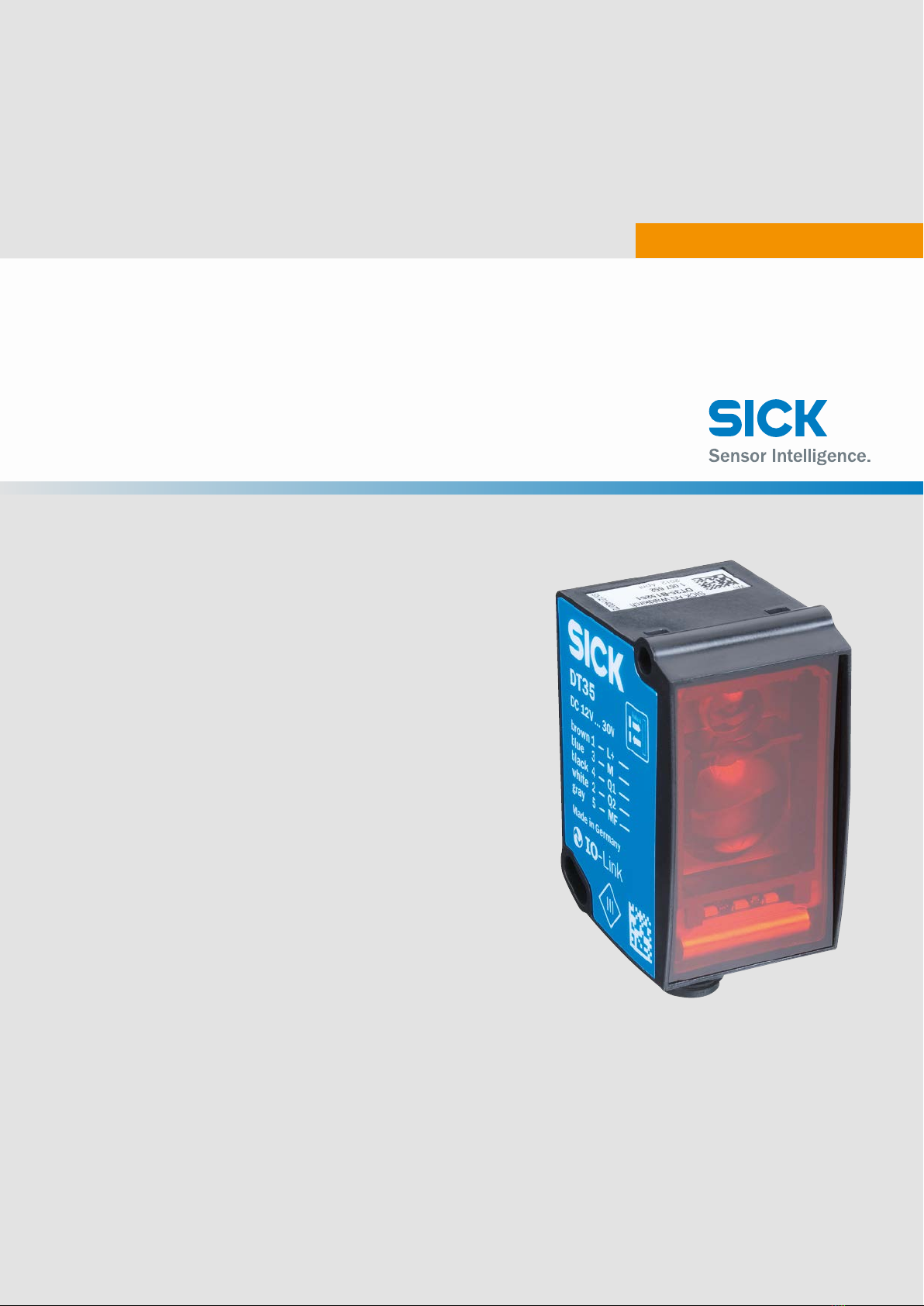
7.4.1 DT35 and DL35 ...................................................... 26
7.4.2 DS35 and DR35...................................................... 27
8 Commissioning ................................................................................ 28
8.1 Performing teach-in ................................................................ 28
8.1.1 Performing one-point teach (DtO).......................... 29
8.1.2 Performing window teach (Wnd)............................ 30
8.1.3 Teaching in the background (ObSB) ...................... 32
8.2 Scaling the analog output ...................................................... 33
8.3 Performing ne teach ............................................................. 34
8.4 Conguring the speed ............................................................ 35
8.5 Expert mode............................................................................ 36
8.6 Resetting the settings to the factory setting......................... 37
8.7 External teach functions......................................................... 37
9 IO-Link interface .............................................................................. 39
9.1 Physical layer .......................................................................... 39
9.2 Process data ........................................................................... 39
9.3 Service data ............................................................................ 41
9.3.1 IO-Link-specic........................................................ 41
9.3.2 SICK-specic – outputs .......................................... 41
9.3.3 SICK-specic – sensor performance ..................... 43
9.3.4 SICK-specic – teach.............................................. 46
9.3.5 SICK-specic – process data ................................. 47
9.3.6 SICK-specic – other settings................................ 47
9.3.7 System command ................................................... 48
9.4 Error codes.............................................................................. 48
10 Other functions ................................................................................ 49
10.1 Output as signal level warning (OWS )................................... 49
10.2 Switch delay ............................................................................ 50
10.3 Find me!................................................................................... 51
10.4 Output as alarm output .......................................................... 51
10.5 Centering function or center displacement .......................... 52
10.6 Teach conrmation function .................................................. 53
10.7 Device backward compatibility (DBC).................................... 54
10.8 Timer function......................................................................... 54

8014868/YIF1/2020-10-19 • © SICK AG • Subject to change without notice 5
Table of contents
11 Cleaning and maintenance ............................................................. 55
11.1 Cleaning .................................................................................. 55
11.2 Maintenance ........................................................................... 55
12 Disposal ............................................................................................ 55
13 Technical data.................................................................................. 56
13.1 Dimensions ............................................................................. 57
13.2 Laser/optics............................................................................ 58
13.3 Performance data................................................................... 58
13.4 Supply...................................................................................... 59
13.5 Inputs....................................................................................... 60
13.6 Outputs.................................................................................... 60
13.7 Interfaces ................................................................................ 60
13.8 Ambient data........................................................................... 60
13.9 Structural design .................................................................... 61
13.10 "Repeatability" diagrams ....................................................... 61
13.10.1 DT35 and DS35 models......................................... 61
13.10.2 DL35 and DR35 models......................................... 63
14 Accessories ...................................................................................... 64
15 Congurationoverview.................................................................... 65
Index .......................................................................................................... 66

6 © SICK AG • Subject to change without notice • 8014868/YIF1/2020-10-19

8014868/YIF1/2020-10-19 • © SICK AG • Subject to change without notice 7
Important safety notes
NFPA79 applications only.
Adapters including eld wiring cables are available.
→ See “www.sick.com/Dx35”
CAUTION!
Using control elements or settings or executing proce-
dures other than those specied in this document may
result in dangerous exposure to radiation.

General information
8 © SICK AG • Subject to change without notice • 8014868/YIF1/2020-10-19
1 General information
1.1 Information about these operating instructions
These operating instructions provide important information on how to use
devices from SICK AG.
Prerequisites for safe work are:
• Compliance with all safety notes and handling instructions supplied
• Compliance with local work safety regulations and general safety regula-
tions for device applications
The operating instructions are intended to be used by qualied personnel
and electrical specialists.
NOTE!
Read these operating instructions carefully to familiarize
yourself with the device and its functions before com-
mencing any work.
The operating instructions are an integral part of the product. Store the in-
structions in the immediate vicinity of the device so they remain accessible
to sta at all times. Should the device be passed on to a third party, these
operating instructions should be handed over with it.
These operating instructions do not provide information on operating the
machine or system in which the device is integrated. For information about
this, refer to the operating instructions of the specic machine.

8014868/YIF1/2020-10-19 • © SICK AG • Subject to change without notice 9
General information
1.2 Explanation of symbols
Warnings Warnings in these operating instructions are labeled with symbols. The
warnings are introduced by signal words that indicate the extent of the
danger.
These warnings must be observed at all times and care must be taken to
avoid accidents, personal injury, and material damage.
DANGER!
… indicates a situation of imminent danger, which will
lead to a fatality or serious injuries if not prevented.
WARNING!
… indicates a potentially dangerous situation, which may
lead to a fatality or serious injuries if not prevented.
CAUTION!
… indicates a potentially dangerous situation, which may
lead to minor/slight injuries if not prevented.
IMPORTANT!
… indicates a possible hazardous situation which may
lead to physical damage if it is not avoided.
Tips and recommendations
NOTE!
… highlights useful tips and recommendations as well as
information for ecient and trouble-free operation.

General information
10 © SICK AG • Subject to change without notice • 8014868/YIF1/2020-10-19
1.3 Limitation of liability
Applicable standards and regulations, the latest state of technological
development, and many years of knowledge and experience have all been
taken into account when assembling the data and information contained in
these operating instructions.
The manufacturer accepts no liability for damage caused by:
• Failing to observe the operating instructions
• Improper use
• Use by untrained personnel
• Unauthorized conversions
• Technical modications
• use of unauthorized spare parts/consumable parts.
The actual scope of delivery may dier from the features and illustrations
shown here where special variants are involved, if optional extras have
been ordered, or as a result of the latest technical changes.
1.4 Scopeofdelivery
Included in scope of delivery:
• DS35, DT35, DL35 or DR35 distance sensor
(→See “Type code”, Chapter 3.2 on page 16)
• Optional: Accessories (→ See Chapter 14 on page 64)
Supplied documentation:
• Safety notes
1.5 Customerservice
If you require any technical information, our customer service department
will be happy to help.
See the back page for relevant contact details.
NOTE!
Before calling, make a note of all type label data such as
type code, serial number, etc., to ensure faster process-
ing.
1.6 EU declaration of conformity
→ You can download the EU declaration of conformity from “www.sick.
com/Dx35”.

Safety
12 © SICK AG • Subject to change without notice • 8014868/YIF1/2020-10-19
2 Safety
2.1 Intended use
The DS35 and DT35 distance sensors are opto-electronic sensors for per-
forming non-contact distance measurement of objects.
The DL35 and DR35 distance sensors are opto-electronic sensors for per-
forming non-contact distance measurement on reective tape.
SICK AG assumes no liability for losses or damage arising from the use of
the product, either directly or indirectly. This applies in particular to use of
the product that does not conform to its intended purpose and is neither
described nor mentioned in this documentation.
2.2 Improper use
DS35, DT35, DL35, and DR35 distance sensors do not constitute safety
components in accordance with the EC Machinery Directive (2006/42/EC).
The distance sensors must not be used in areas having a danger of explo-
sions.
Any other use that is not described as intended use is prohibited.
Never install or connect accessories if their quantity and composition are
not clearly specied, or if they have not been approved by SICK AG.
WARNING!
Danger due to improper use!
Any improper use can result in dangerous situations.
For this reason:
• Distance sensors should be used only according to
intended use specications.
• All information in these operating instructions must be
strictly observed.

8014868/YIF1/2020-10-19 • © SICK AG • Subject to change without notice 13
Safety
2.3 Requirements for skilled persons and operating personnel
WARNING!
Riskofinjuryduetoinsucienttraining!
Improper handling may result in considerable personal
injury and material damage.
For this reason:
• All work must only ever be carried out by the stipulated
persons.
The operating instructions state the following qualication requirements for
the various areas of work:
• Qualiedpersonnel
are able to carry out the work assigned to them and independently
recognize potential risks due to their specialist training, knowledge, and
experience, as well as knowledge of the relevant regulations.
• Electrical specialists
are able to carry out work on electrical systems and independently
recognize potential risks due to their specialist training, knowledge, and
experience, as well as knowledge of the relevant standards and regula-
tions.
The electrician must comply with the provisions of the locally applicable
work safety regulation.
2.4 Warningsymbolonthedevice
Laser class 2 Distance sensors with a class 2 laser according to EN/IEC60825-1:2014
(identical laser class for issue EN/IEC 60825-1:2007) carry the following
warning label.
LASER APERTURE
MAX. OUTPUT ≤ 250mW
PULSE LENGHT = 4ns
WAVELENGHT = 658nm
EN/IEC 60825-1:2014
Complies with 21 CFR
1040.10 and 1040.11
except for deviations
pursuant to laser notice
No. 50, dated June 24, 2007
LASER
2
• Laser output aperture label, →
See Fig. 5 on page 17
• CAUTION LASER RADIATION
Do not look into the beam.
Laser class 2 product
• Specication of maximum output
power, pulse length, wavelength
• EN/IEC 60825-1:2014:
Complies with 21 CFR 1040.10
and 1040.11 except for tolerances
according to Laser Notice No. 50
dated 24/06/2007
Fig. 1: Warning symbol on sensor with class 2 laser

Safety
14 © SICK AG • Subject to change without notice • 8014868/YIF1/2020-10-19
Laser class 1 Distance sensors with a class 1 laser according to EN/IEC60825-1:2014
(identical laser class for issue EN/IEC 60825-1:2007) carry the following
warning label.
LASER APERTURE
EN/IEC 60825-1:2014
Complies with 21 CFR
1040.10 and 1040.11
except for deviations
pursuant to laser notice
No. 50, dated June 24, 2007
LASER
1
• Laser output aperture label, →
see Fig. 5 on page 17
• CAUTION LASER RADIATION
Laser class 1 product
• EN/IEC 60825-1:2014:
Complies with 21 CFR 1040.10
and 1040.11 except for tolerances
according to Laser Notice No. 50
dated 24/06/2007
Fig. 2: Warning symbol on sensor with class 1 laser
Laser class 1 product
Laserwarninglabelposition The laser warning label is located on the right side of the housing.
Complies with 21 CFR
1040.10 and 1040.11
except for deviations
pursuant to laser notice
No. 50, dated June 24, 2007
EN/IEC 60825-1:2014
MAX. OUTPUT
≤
250
mW
PULSELENGTH = 4ns
WAVELENGTH = 658nm
LASER APERTURE
Fig. 3: Laser warning label position
2.5 Operational safety and particular hazards
Please observe the safety notes and the warnings listed here and in other
chapters of these operating instructions to reduce the possibility of risks to
health and avoid dangerous situations.

8014868/YIF1/2020-10-19 • © SICK AG • Subject to change without notice 15
Identication
2.6 Hazardwarningsandoperational safety
Laser radiation For your own safety, please read and observe the following note:
WARNING!
Risk of injury from laser radiation!
Looking directly into the laser beam may result in eye
injury.
• Do not look into the laser beam.
3 Identication
3.1 Type label
The distance sensor includes the following type label:
1
23 5
4
SICK AG Waldkirch
Fig. 4: “Dx35 distance sensor” type label
1 2D code
2 For type description, see type code
3 Article number (order number)
4 Year and month of manufacture
5 Serial number

Identication
16 © SICK AG • Subject to change without notice • 8014868/YIF1/2020-10-19
3.2 Type code
D T 3 5 – B 1 5 5 5 1 X
1234 567891011
Position Description
1 … 4 Sub product family
DS35 Distance sensor, switching on natural objects
DT35 Distance sensor, measurement on natural objects
DL35 Distance sensor, measurement on reective tape
DR35 Distance sensor, switching on reective tape
5Outputsignalswitchingdevice
B B-type or push-pull output
6Speed, sensing range
1 Adjustable
7Connection type
5 M12 plug, 5-pin
8Light sender, laser class
2 Red light, laser class 2
5 Red light, laser class 1
8 Infrared light, laser class 1
9Interface
2 Switching outputs Q1 and Q2 and IO-Link
5 Analog current or voltage output (Q2), switching output (Q1) and IO-Link
10 Measurement
1 Optimized for natural objects
2 Optimized for reective tape
11 Other info
X Additional characters possible
Table 1: “Dx35 distance sensor” type code

8014868/YIF1/2020-10-19 • © SICK AG • Subject to change without notice 17
Design and function
4 Design and function
4.1 Structure
Fig. 5: ”Dx35 distance sensor” structure and function
1 Optical axis, sender
Laser output aperture corresponds to the front screen at the height of the
position shown.
2 Optical axis, receiver
3 Reference surface ( corresponds to 0 mm)
4 M4 xing hole
5 Teach-in LEDs
6 Q1/Q2 status LEDs
7 Status indicator LED
8 Operating pushbuttons
Q1 and Q2 status LEDs (continued on
next page) LED Description
Q1 Q1 switching output indicator
• Orange LED: switching output active
• LED o: switching output inactive
Q2 Q2 switching output/Qa analog output indicator
• LED orange: Switching output active/measured value
within analog output scaling
• LED o: Switching output inactive/measured value
outside analog output scaling
Q1 and Q2
in run mode
• "Q1" and "Q2" LEDs ash alternately for longer than 10
seconds: fault exists. Check general conditions such as
supply voltage, temperature range, EMC disturbances,
etc.
Q1 and Q2
in teach mode
• "Q1" and "Q2" LEDs ash simultaneously: teach is being
performed.
• "Q1" and "Q2" LEDs ash alternately for 5 seconds:
teach failed.

Design and function
18 © SICK AG • Subject to change without notice • 8014868/YIF1/2020-10-19
Q1 and Q2 status LEDs (continued) LED Description
Q1 and Q2 in align-
ment mode
Alignment quality indicator (IR models only)
• Slow ashing (approx. 1 Hz): poor alignment quality
• Rapid ashing (approx. 15 Hz): good alignment quality
Table 2: Q1 and Q2 status LEDs
Status indicator LED LED Description
Run Operating indicator
• Rear LED green/front LED orange: Supply voltage pres-
ent
• LED o: Supply voltage o
Table 3: Status indicator LED
Teach-in LEDs
(continued on next page) LED Description
Q1 near, Q1 far,
Q2 near, Q2 far,
in teach mode
• Perform one-point or window teach.
• One of the LEDs lights up: Teach can be performed.
• One of the LEDs ashes: Fine teach can be performed.
Q1 near + Q1 far
(ObSB)
in teach mode
Teach in ObSB or background for switching output Q1.
• Both LEDs light up: Teach can be performed.
• Both LEDs ash: Fine teach can be performed.
Q2 near + Q2 far
(ObSB)
in teach mode
Teach in ObSB or background for switching output Q2.
• Both LEDs light up: Teach can be performed.
• Both LEDs ash: Fine teach can be performed.
slow … fast
in teach mode
Set speed. "Slow … fast" LED ashes cyclically:
• 1 x: Super-slow
• 2 x: Slow
• 3 x: Medium
• 4 x: Fast
• 5 x: Super-fast
"Slow … fast" LED lights up continuously:
• Expert or expert setting, adjustable only via IO-Link
→ See Chapter 9.3.3 on page 43
Q1 near, Q1 far,
Q2 near, Q2 far,
slow … fast
in alignment mode
Alignment quality indicator (IR models only)
• The greater the number of LEDs that light up, the better
the teach-in quality.

8014868/YIF1/2020-10-19 • © SICK AG • Subject to change without notice 19
Design and function
Teach-in LEDs (continued) LED Description
Q1 near, Q1 far,
Q2 near, Q2 far,
slow … fast
in expert mode
• “Q1 near” LED lights up and “slow … fast” LED ashes
cyclically: Select function for multifunctional input “MF”.
–1 x: Teach
– 2 x: Laser o
–3 x: Inactive
• “Q1 far” LED lights up and “slow … fast” LED ashes
cyclically: Select level for multifunctional input “MF”.
–1 x: Low active
–2 x: High active
• DT35 and DL35 models only
"Q2 near" LED lights up and "slow … fast" LED ashes
cyclically: Select Q2 output function.
–1 x: 4 ... 20 mA
–2 x: 0 ... 10 V
–3 x: Switching
Table 4: Teach-in LEDs
Operating pushbuttons Operating button Description
select (–) • In run mode
Press select pushbutton longer than 5 seconds: Enter or
leave teach mode.
• In teach mode
Press select pushbutton: Select function.
• In ne teach mode
Move previously taught-in switching point by –10 mm.
set (+) • In run mode (IR models only)
Press set pushbutton longer than 5 seconds: Enter or
leave alignment mode.
• In teach mode
Press set pushbutton: Perform teach, select function.
• In ne teach mode
Move previously taught-in switching point by +10 mm.
select + set • In run mode
Press select and set pushbuttons simultaneously for
longer than 10 seconds: Enter or leave expert mode.
• In teach mode
After previously performing teach, press select and set
pushbuttons simultaneously for less than 1 second:
Enter or leave ne teach.
Table 5: Operating pushbuttons

Design and function
20 © SICK AG • Subject to change without notice • 8014868/YIF1/2020-10-19
4.2 Function
The DS35 and DT35 distance sensors are opto-electronic sensors for per-
forming non-contact distance measurement of objects.
The DL35 and DR35 distance sensors are opto-electronic sensors for per-
forming non-contact distance measurement on reective tape.
If Q1 and Q2 are used as switching outputs, the following operation modes
are available: Distance to Object (DtO), Window (Wnd), and Object between
Sensor and Background (ObSB). The measured distance value can be
transferred cyclically over IO-Link.
For the DT35 and DL35 models, the Q2 output can be congured as a cur-
rent output (4 … 20 mA), voltage output (0 … 10 V), or switching output.
This manual suits for next models
4
Table of contents
Other SICK Accessories manuals

SICK
SICK T-EASIC FTS User manual

SICK
SICK KTX Prime KTX-WB91141259ZZZZ User manual

SICK
SICK WL34 User manual

SICK
SICK LMS400 Reference guide

SICK
SICK MRS1000 User manual

SICK
SICK PowerProx Micro WTT2SL Series User manual

SICK
SICK DS500 User manual

SICK
SICK CQF16 User manual

SICK
SICK MultiPulse WTB4-3P2100S13 User manual

SICK
SICK Bulkscan User manual